B4SVR40AWireless Audio/Video Sender
Authinx Inc.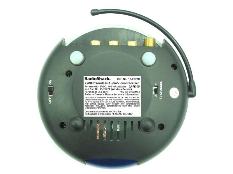
Click to zoom
Application Details
- Equipment Class
- DSC - Part 15 Security/Remote Control Transmitter
- Date of Grant
- Nov 21, 2002
- Application Purpose
- Original Equipment
- Date of Application
- Nov 21, 2002
- Equipment Note
- Wireless Audio/Video Sender
- Frequency Range
- 433.00000000 - 433.00000000
- Company
- Authinx Inc.
- Country
- United States
Documents & Files
Document Text
Text extracted from the exhibit documents filed with the FCC. Open a document above to read the original.
Users Manual
C AT . N O . 15-2572 W W W W W IRELESS IRELESS IRELESS IRELESS IRELESS A A A A A UDIO UDIO UDIO UDIO UDIO /V /V /V /V /V IDEO IDEO IDEO IDEO IDEO S S S S S ENDER ENDER ENDER ENDER ENDER with IR Extender Feature S ENDER 15-2572T OWNER’S MANUAL S ENDER 15-2572T 3 3 3 3 3 2 2 2 2 2 FCC C AUTION THIS DEVICE COMPLIES WITH PART 15 OF THE FCC RULES.OPERATION IS SUBJECT TO THE FOLLOWING TWOCONDITIONS:(1) THIS DEVICE MAY NOT CAUSE HARMFUL INTERFERENCE, AND (2) THIS DEVICE MUST ACCEPT ANY INTERFERENCE RECEIVED, INCLUDING INTERFERENCE THAT MAY CAUSEUNDESIRED OPERATION. NOTE: Modifications to this product will void the user’s authority to operate this equipment. I NTRODUCTION Your Wireless Audio/Video Sender system consists of a Sender unit whichyou connect to your satellite receiver, DVD player, etc., and a Receiverunit that you connect to a TV anywhere in your home. The Audio/VideoSender converts the A/V signal from your A/V product into a 2.4 GHzwireless Radio Frequency (RF) signal and transmits it (even through walls)to the Audio/Video Receiver unit. The Audio/Video Receiver converts thesignal back to an A/V signal and passes it through a cable to your TV’sCOAX input, or A/V input jacks.The Audio/Video Sender system also includes an IR Extender feature. Thislets you remotely control the A/V product that the Sender is connected to,from the location where the Receiver is located. For example, you cancontrol a DVD Player in your living room, while watching it on a TV inyour bedroom.There are just a few simple steps to follow to hook up your Audio/VideoSender system to a satellite receiver, VCR, DVD Player, or Cable Box. C ONTENTS I NTRODUCTION ........................................................................ 3 C ONTROLS AND C ONNECTIONS .................................................. 4 S ENDER ............................................................................ 4 R ECEIVER .......................................................................... 5 C ONNECTING U P ..................................................................... 6 H OOKING UP THE S ENDER .................................................... 6 H OOKING UP THE R ECEIVER ................................................. 8 F INE TUNING YOUR S YSTEM .................................................... 10 IR E XTENDER F EATURE ......................................................... 11 5 5 5 5 5 4 4 4 4 4 CHANNEL ONOFF TV C HANN EL 34 ONOFF CHANNEL RF Antenna(for use with the IRExtender feature) Power Supply Jack 2.4 GHz Antenna 2.4 GHz Channel Switch A/V In Jacks 2.4 GHz ChannelSwitch (underneath2.4 GHz Antenna). C ONTROLS AND C ONNECTIONS Audio/Video Receiver Audio/Video Sender ON-OFF Switch (on side) A/V Out Jacks COAX out Channel 3/4 switch IR Extender Jack RF Antenna(for use with the IRExtender feature) Power Supply Jack ON-OFF Switch (on side) 7 7 7 7 7 6 6 6 6 6 Vid eo Audi o Out In Out Vid eo Audi o A/V Component Antenna To TVAntenn a TV A/V Component Antenna To TVAntenna TV Out Vid eo Audi o UHF/VHFTo TVUHF/VHF C ONNECTING U P Hooking up the Audio/Video Sender1. Connect one set of Audio/Video cables to the VIDEO and AUDIO jacks of your Audio/Video Sender. Take care to match the colors of theplugs on the cable with the jacks on the Audio/Video Sender. 2. Connect the other end of the cable to the Audio/Video OUT jacks on your TV. Take care to match the colors of the plugs on the cable withthe jacks on the TV. If the jacks on the TV are colored differently,connect the yellow plug to the jack labelled VIDEO, the red plug to thejack labelled AUDIO RIGHT and the white plug to the jack labeledAUDIO LEFT. See diagram A below.Note: If your TV does not include Audio/Video OUT jacks, you will need to remake the connections as shown in diagram B) using theTV antenna (coaxial) connections to link up a Satellite Receiver(DBS), or Cable Box, or VCR, or DVD Player to your TV. 3. Plug the Audio/Video Sender’s Power Supply into a convenient 120 volt wall outlet and plug its jack into the Audio/Video Sender. 4. Position the Audio/Video Sender in a convenient location such as on top of your TV and orient the antenna so that the flat side points in thedirection of the room where you will be installing the Receiver. If you have several A/Vcomponents:If you have two or more A/Vcomponents (e.g. Satellite Receiver(DBS), VCR, Cable Box, DVD Player,etc.) that you want to watch in anotherroom, they will probably already behooked up to the local TV in series (seethe diagram to the right). To connect theAudio/Video Sender you just need toidentify the last component in the chainand connect its LINE OUT jacks to theAudio/Video Sender’s A/V IN jacks.If the last component in the chain doesnot have spare LINE OUT jacks,reconnect the local TV to the lastcomponent in the chain using a coaxialcable to connect to the VHF/UHF jack,then use the A/V connections for theAudio/Video Sender. A) Connections for a TV with A/V OUT jacks. B) Connections for a TV without A/V OUT jacks. A/V Cables CoaxialCable TV UHF/VHF Satellite Receiver Out Vid eo Audi o UHF/VHFTo TV In Cable Box Out Vid eo Audi o In DVD Player Out Vid eo Audi o In 9 9 9 9 9 8 8 8 8 8 Hooking up the Audio/Video Receiver1. Connect a set of Audio/Video cables to the A/V OUT jacks of your Audio/Video Receiver. Connect the other end to your TV. 2. Plug the Audio/Video Receiver’s Power Supply into a 120 volt wall outlet and plug its jack into the Audio/Video Receiver. 3. Position the Audio/Video Receiver in a convenient location such as on top of your TV and orient the antenna so that the flat side points in thedirection of the room where you set up the Audio/Video Sender. Vid eo Audi o In A/V Component TV Out Vid eo Audi o In Vide o Audi o TV In UHF/VHF(COAX) In TV 1 2 TV UHF/VHFFrom ant enna If your TV does not have A/V connectors:You can use the supplied coaxial cable to connect the TV OUT COAXsocket on the Audio/Video Receiver to the Antenna input on your TV. Ifyou already have an antenna …
Text truncated - open the document above for the full version.
Block Diagram
2.4GHz Patch Antenna Low PassFilterHigh PassFilter De-emphasis FM DemodulatorFM Demodulator Audio DriverAudio DriverVideo Driver Left Audio Output Right Audio Output Video Output RF Output VHF Modulator 2.4GHz RF Receiver 4-Channels Selector IR 433MHz transmitter Amplifier IR Sensor Block Diagram for Video Sender Receiver (VR40A)
ID Label/Location Info
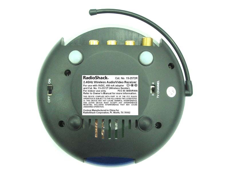
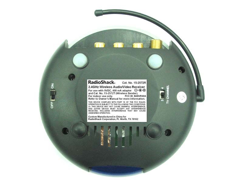
2.4GHz Wireless Audio/Video Receiver ® Cat. No. 15-2572R For use with Cat. No. 15-2572T (Wireless Sender). For indoor use only. Refer to Owner’s Manual for more information. 9VDC, 400 mA adapter and Custom Manufactured in China for RadioShack Corporation, Ft. Worth, TX 76102 FCC ID: B4SVR40A THIS DEVICE COMPLIES WITH PART 15 OF THE FCC RULES. OPERATION IS SUBJECT TO THE FOLLOWING TWO CONDITIONS: (1) THIS DEVICE MAY NOT CAUSE HARMFUL INTERFERENCE, AND (2)THIS DEVICE MUST ACCEPT ANY INTERFERENCE RECEIVED, INCLUDING INTERFERENCE THAT MAY CAUSE UNDESIRED OPERATION. – + •
Operational Description
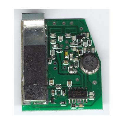
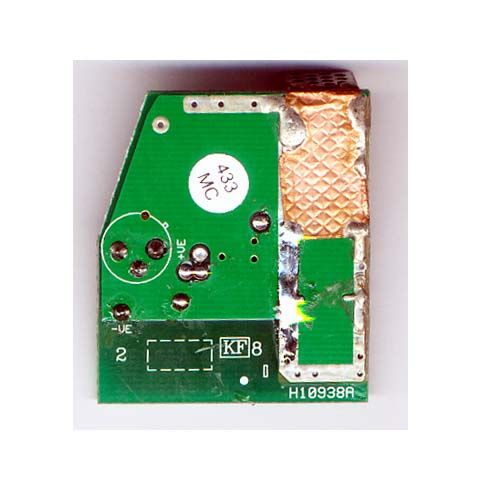
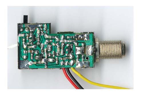
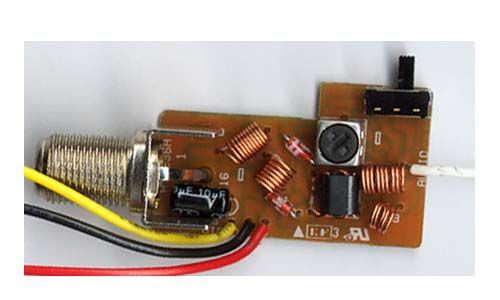
VR40A Operational Description-433 MHz transmitter: The VR40A contains a 433 MHz pulsed transmitter. The transmitter is used to extend Infrared Transmitter range. The Infrared Pulse Coded remote control TV/VCR/DVD commands are received by the VR40A and used as an input to the 433 MHz pulsed transmitter. This signal is then transmitted via the loop antenna to the VT40A, where the process is reversed.
Schematics
RFMOD_03.sch-1 - Thu Oct 31 07:27:44 2002 H11001B.sch-1 - Tue Nov 05 22:12:21 2002
Test Report
Test Report No. R-9688-1 FCC ID: B4SVR40A APPLICANT X-10 (USA), Inc. 19823 58 th Place S. Kent, WA 98032 MANUFACTURER X-10 Electronics Shenzhen Co. Ltd. X-10 Building Labour Industrial District Shenzhen, Xixiang, Bao An Guang Dong, China, 518102 TEST SPECIFICATION: FCC Rules and Regulations Part 15, Subpart C, Para. 15.231 TEST PROCEDURE: ANSI C63.4:2000 TEST SAMPLE DESCRIPTION BRANDNAME: X-10 (USA) MODEL: VR40A TYPE: Pulsed Transmitter POWER REQUIREMENTS: 115 VAC, 60 Hz FREQUENCY OF OPERATION: 433 MHz TESTS PERFORMED Para. 15.231(b), Radiated Emissions, Fundamental and Harmonics Para. 15.209, Radiated Emissions, Spurious Case Para. 15.209, AC Line Conducted Emissions Para. 15.35, Duty Cycle Determination Para. 15.231(c), Occupied Bandwidth REPORT OF MEASUREMENTS Applicant: X-10 (USA), Inc. Device: Pulsed Transmitter FCC ID: B4SVR40A Test Report No. R-9688-1 FCC ID: B4SVR40A Power Requirements: 115 VAC, 60 Hz Applicable Rule Section: Part 15, Subpart C, Section 15.231 Test Report No. R-9688-1 FCC ID: B4SVR40A REPORT OF MEASUREMENTS (continued) TEST RESULTS 15.231 (a): This device is used as a remote control transmitter. 15.231 (a)(1) & The transmitter is automatically operated and ceases transmission within 5 15.231(a)(2): seconds after deactivation. 15.231 (a)(3): The transmitter does not perform periodic transmissions. 15.231 (b): The fundamental field strength did not exceed 11,000 μV/M (Average) at a test distance of 3 meters. In addition, the requirements of section 15.35 for averaging pulsed emissions and for limiting peak emissions were met. The field strength of harmonic and spurious emissions did not exceed 1,100 μV/M (AVERAGE). DETERMINATION OF FIELD STRENGTH LIMITS The field strength limits shown below are found in Section 15.231. Frequency Limit F1 = 260 3750 = L1 Fo = 434 Lo F2 = 470 12500 = L2 The formula below was utilized to determine the limits: Limit = L1 + [(Fo-F1)(L2-L1)/(F2-F1)] Solving yields: Fundamental Limit = 11,000 μV/M (AVERAGE) @ 3 Meters Harmonic Limit = 1,100 μV/M (AVERAGE) @ 3 Meters Test Report No. R-9688-1 FCC ID: B4SVR40A REPORT OF MEASUREMENTS (continued) DUTY CYCLE DETERMINATION The unit’s RF output was directly coupled to the input of the spectrum analyzer. The analyzer was set for a frequency span of 0Hz. The sweep time was then adjusted in order to display one full pulse train. The transmitter on time was then summed and compared to the time for one full cycle in order to obtain the duty cycle.( See plots for additional information) Transmitter On Time = 13.7 milliseconds (maximum- worst case in 100 ms) Transmitter Cycle Time = 112.2 milliseconds Transmitter Duty Cycle = 13.7 % CALCULATION: 3 x 1.9 milliseconds (large pulse) = 5.7 milliseconds 8 x 1 milliseconds (small pulse) = 8 milliseconds 8 + 5.7 = 13.7 milliseconds Duty Cycle (13.7/100) = 13.7 % Correction Factor = 20 log(0.137) = -17.3dB SPECTRUM ANALYZER DESENSITIZATION CONSIDERATIONS Due to the nature of the emissions being measured, care was taken to ensure that the resolution bandwidth of the spectrum analyzer was adequate to provide accurate measurements. The following formula was utilized: Setting pulse desensitization equal to zero and utilizing the minimum observed pulse width of 1.0 millisecond yields a minimum required bandwidth of 666.7 Hz. FCC specified bandwidths of 100kHz and 1MHz were utilized below and above 1GHz, respectively. Test Report No. R-9688-1 FCC ID: B4SVR40A GENERAL NOTES All readings were taken utilizing a peak detector function at a test distance of 3 meters. The duty cycle was applied to the peak readings in order to determine the average value of the emissions. The frequency range was scanned from 30 MHz to 4.4 GHz. All emissions not reported were more than 20 dB below the specified limit. Test Report No. R-9688-1 FCC ID: B4SVR40A Test Setup Photographs
Test Report
Retlif Testing Laboratories R Data Sheet 1 of 4 Test Method: FCC Part 15 Subpart C Radiated Emissions, Fundamental & Harmonic Emissions Customer: X-10 (USA), Inc. Job No. R-9688-1 Test Sample: 433 MHz Pulsed Transmitter Paragraph: 15.231 Model No.: VR40A FCC ID: B4SVR40A Operating Mode: Continuously transmitting a 433 MHz signal Technician: Peter Lananna Date: November 12, 2002 Notes: Test Distance: 3 Meters Detector: Peak, Unless otherwise specified Test Freq. Antenna Pol./Height EUT Orientation Meter Reading Correction Factor Corrected Reading Converted Reading Peak Limit MHz (V/H)/Meters X / Y / Z dBuV dB dBuV/m uV/m uV/m 433 H / 1.0 X 89.7-0.7 89.028183.8 110000 | H / 2.3 Y 88.6 -0.7 87.9 24831.3 | | H / 2.3 Z 91.2 -0.7 90.5 33496.5 | | V / 2.5 X 91.3 -0.7 90.6 33884.4 | | V / 2.3 Y 89.7 -0.7 89.0 28183.8 | 433 V / 2.3 Z 91.1 -0.7 90.4 33113.1 110000 866 H / 1.0 X 59.7 8.1 67.8 2454.7* 11000 | H / 1.0 Y 59.7 8.1 67.8 2454.7* | | H / 1.0 Z 59.7 8.1 67.8 2454.7* | | V / 1.0 X 59.7 8.1 67.8 2454.7* | | V / 1.0 Y 59.7 8.1 67.8 2454.7* | 866 V / 1.0 Z 59.7 8.1 67.8 2454.7* 11000 1299 H / 2.0 X 52.3 -0.6 51.7 384.6 11000 | H / 1.5 Y 50.2 -0.6 49.6 302.0 | | H / 2.3 Z 55.0 -0.6 54.4 524.8 | | V / 1.5 X 53.8 -0.6 53.2 457.1 | | V / 1.3 Y 52.8 -0.6 52.2 407.4 | 1299 V / 1.5 Z 50.4 -0.6 49.8 309.0 11000 1732 H / 1.3 X 54.9 4.1 59.0 891.3 11000 | H / 1.8 Y 53.3 4.1 57.4 741.3 | | H / 2.0 Z 57.7 4.1 61.8 1230.3 | | V / 1.5 X 54.9 4.1 59.0 891.3 | | V / 1.0 Y 55.5 4.1 59.6 955.0 | 1732 V / 1.5 Z 54.7 4.1 58.8 871.0 11000 2165 H / 1.8 X 54.0 1.2 55.2 575.4 11000 | H / 1.0 Y 55.8 1.2 57.0 707.9 | | H / 1.8 Z 57.4 1.2 58.6 851.1 | | V / 1.5 X 53.1 1.2 54.3 518.8 | | V / 2.3 Y 55.3 1.2 56.5 668.3 | 2165 V / 1.5 Z 56.6 1.2 57.8 776.2 11000 The frequency range was scanned from 30 MHz to 4.4GHz. All emissions not recorded were more Than 10 dB below the specified limit. Emissions from the EUT do not exceed the specified limits. *= High ambient signal masking harmonic. Retlif Job Number R-9688-1 Retlif Testing Laboratories R Data Sheet 2 of 4 Test Method: FCC Part 15 Subpart C Radiated Emissions, Fundamental & Harmonic Emissions Customer: X-10 (USA), Inc. Job No. R-9688-1 Test Sample: 433 MHz Pulsed Transmitter Paragraph: 15.231 Model No.: VR40A FCC ID: B4SVR40A Operating Mode: Continuously transmitting a 433 MHz signal Technician: Peter Lananna Date: November 12, 2002 Notes: Test Distance: 3 Meters Detector: Peak, unless otherwise specified Test Freq. Antenna Pol./Height EUT Orientation Meter Reading Correction Factor Corrected Reading Converted Reading Peak Limit MHz (V/H)-Meters X / Y / Z dBuV dB dBuV/m uV/m uV/m 2598 H / 3.0 X 48.54.8 53.3462.4 11000 | H / 3.0 Y 47.2 4.8 52.0 398.1 | | H / 2.0 Z 57.0 4.8 61.8 1230.3 | | V / 2.0 X 48.9 4.8 53.7 484.2 | | V / 1.3 Y 51.7 4.8 56.5 668.3 | 2598 V / 1.8 Z 47.9 4.8 52.7 431.5 11000 3031 H / 1.0 X 38.9 6.4 45.3 184.1* 11000 | H / 1.0 Y 38.9 6.4 45.3 184.1* | | H / 1.0 Z 38.9 6.4 45.3 184.1* | | V / 1.0 X 38.9 6.4 45.3 184.1* | | V / 1.0 Y 38.9 6.4 45.3 184.1* | 3031 V / 1.0 Z 38.9 6.4 45.3 184.1* 11000 3464 H / 1.0 X 38.0 8.3 46.3 206.5* 11000 | H / 1.0 Y 38.0 8.3 46.3 206.5* | | H / 1.0 Z 38.0 8.3 46.3 206.5* | | V / 1.0 X 38.0 8.3 46.3 206.5* | | V / 1.0 Y 38.0 8.3 46.3 206.5* | 3464 V / 1.0 Z 38.0 8.3 46.3 206.5* 11000 3897 H / 1.0 X 38.4 9.8 48.2 257.0* 5000 | H / 1.0 Y 38.4 9.8 48.2 257.0* | | H / 1.0 Z 38.4 9.8 48.2 257.0* | | V / 1.0 X 38.4 9.8 48.2 257.0* | | V / 1.0 Y 38.4 9.8 48.2 257.0* | 3897 V / 1.0 Z 38.4 9.8 48.2 257.0* 5000 4330 H / 1.0 X 38.6 11.0 49.6 302.0* 5000 | H / 1.0 Y 38.6 11.0 49.6 302.0* | | H / 1.0 Z 38.6 11.0 49.6 302.0* | | V / 1.0 X 38.6 11.0 49.6 302.0* | | V / 1.0 Y 38.6 11.0 49.6 302.0* | 4330 V / 1.0 Z 38.6 11.0 49.6 302.0* 5000 The frequency range was scanned from 30 MHz to 4.4 GHz. All emissions not recorded were more Than 10 dB below the specified limit. Emissions from the EUT do not exceed the specified limits. *=Noise Floor Measurements ( Minimum system sensitivity) Retlif Job Number R-9688-1 Retlif Testing Laboratories R Data Sheet 3 of 4 Test Method: FCC Part 15 Subpart C Radiated Emissions, Fundamental & Harmonic Emissions Customer: X-10 (USA), Inc. Job No. R-9688-1 Test Sample: 433 MHz Pulsed Transmitter Paragraph: 15.231 Model No.: VR40A FCC ID: B4SVR40A Operating Mode: Continuously transmitting a 433 MHz signal Technician: Peter Lananna Date: November 12, 2002 Notes: Test Distance: 3 Meters Duty Cycle: 13.7% Detector: Peak, unless otherwise specified Duty Cycle Correction: -17.3dB Test Freq. Antenna Pol./Height EUT Orientation Peak Reading Correction Factor Corrected Reading Converted Reading Avg. Limit MHz (V/H)-Meters X / Y / Z dBuV dB dBuV/m uV/m uV/m 433 H / 1.0 X 89.0 -17.3 71.73845.9 11000 | H / 2.3 Y 87.9 -17.3 70.6 3388.4 | | H / 2.3 Z 90.5 -17.3 73.2 4570.9 | | V / 2.5 X 90.6 -17.3 73.3 4623.8 | | V / 2.3 Y 89.0 -17.3 71.7 3845.9 | 433 V / 2.3 Z 90.4 -17.3 73.1 4518.6 11000 866 H / 1.0 X 67.8 -17.3 50.5 335.0* 1100 | H / 1.0 Y 67.8 -17.3 50.5 335.0* | | H / 1.0 Z 67.8 -17.3 50.5 335.0* | | V / 1.0 X 67.8 -17.3 50.5 335.0* | | V / 1.0 Y 67.8 -17.3 50.5 335.0* | 866 V / 1.0 Z 67.8 -17.3 50.5 335.0* 1100 1299 H / 2.0 X 51.7 -17.3 34.4 52.5 1100 | H / 1.5 Y 49.6 -17.3 32.3 41.2 | | H / 2.3 Z 54.4 -17.3 37.1 71.6 | | V / 1.5 X 53.2 -17.3 35.9 62.4 | | V / 1.3 Y 52.2 -17.3 34.9 55.6 | 1299 V / 1.5 Z 49.8 -17.3 32.5 42.2 1100 1732 H / 1.3 X 59.0 -17.3 41.7 121.6 1100 | H / 1.8 Y 57.4 -17.3 40.1 101.2 | | H / 2.0 Z 61.8 -17.3 44.5 167.9 | | V / 1.5 X 59.0 -17.3 41.7 121.6 | | V / 1.0 Y 59.6 -17.3 42.3 130.3 | 1732 V / 1.5 Z 58.8 -17.3 41.5 118.9 1100 2165 H / 1.8 X 55.2 -17.3 37.9 78.5 1100 | H / 1.0 Y 57.0 -17.3 39.7 96.6 | | H / 1.8 Z 58.6 -17.3 41.3 116.1 | | V / 1.5 X 54.3 -17.3 37.0 70.8 | | V / 2.3 Y 56.5 -17.3 39.2 91.2 | 2165 V / 1.5 Z 57.8 -17.3 40.5 105.9 1100 The frequency range was scanned from 30 MHz to 4.4GHz. All emissions not recorded were more Than 10 dB below the specified limit. Emissions from …
Text truncated - open the document above for the full version.
Test Setup Photos
Retlif Testing Laboratories R Test Report No. R-9688-1 FCC ID: B4SVR40A Test Setup Photographs
Contact Information
Applicant
Shane Houshmand(Chief Operating Officer)
Technical Contact
Retlif Testing LaboratoriesThomas J Schneider
[email protected]631 737-1500
795 Marconi · Ronkonkoma, New York · United States
Non-Technical Contact
Retlif Testing LaboratoriesMichelle White
[email protected]631 737-1500
Test Firm
Retlif Testing LaboratoriesMichael Bozza
Technical Specifications
| # | Rule Parts | Frequency Range | Power Output |
|---|---|---|---|
| 1 | 15.231 | 433 MHz - 433 MHz | - |
Other Applications from Authinx Inc.

B4SXC35A
Jun 16, 2011Wireless Color Camera
Equipment Class
DXX - Part 15 Low Power Communication Device Transmitter
B4SVT50
Jun 16, 2011Wireless Audio/Video System
Equipment Class
DXX - Part 15 Low Power Communication Device Transmitter
B4SVR50
Jun 13, 2011Wireless Audio/Video Receiver
Equipment Class
DSC - Part 15 Security/Remote Control Transmitter
B4S-XC30A
Jun 07, 2011Wireless Color Camera
Equipment Class
DXX - Part 15 Low Power Communication Device Transmitter
B4SIR34A
Aug 01, 2010Remote Control Transmitter
Equipment Class
DSC - Part 15 Security/Remote Control Transmitter