B4SVR50AWIRELESS AUDIO/VIDEO RECEIVER
Authinx Inc.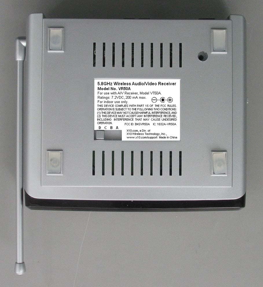
Click to zoom
Application Details
- Equipment Class
- DSC - Part 15 Security/Remote Control Transmitter
- Date of Grant
- Jan 27, 2008
- Application Purpose
- Original Equipment
- Date of Application
- Jan 27, 2008
- Equipment Note
- WIRELESS AUDIO/VIDEO RECEIVER
- Frequency Range
- 433.92000000 - 433.92000000
- Company
- Authinx Inc.
- Country
- United States
Documents & Files
Document Text
Text extracted from the exhibit documents filed with the FCC. Open a document above to read the original.
Users Manual
M ODEL VK50A W W W W W IRELESS IRELESS IRELESS IRELESS IRELESS A A A A A UDIO UDIO UDIO UDIO UDIO /V /V /V /V /V IDEO IDEO IDEO IDEO IDEO S S S S S ENDER ENDER ENDER ENDER ENDER with dual-source input and IR Extender Feature S ENDER - M ODEL VT50A OWNER’S MANUAL R ECEIVER - M ODEL VR50A 3 2 I NTRODUCTION Your Wireless Audio/Video Sender system consists of a Sender unit whichyou connect to your satellite receiver, DVD player, etc., and a Receiverunit that you connect to a TV located somewhere else in your home. TheAudio/Video Sender converts the audio and video output from your A/Vproduct into a 5.8 GHz wireless Radio Frequency (RF) signal andtransmits it (even through walls) to the Audio/Video Receiver. The Audio/Video Receiver converts the signal back to an A/V signal and passes itthrough a cable to your TV’s Audio/Video input jacks.You can connect two A/V devices to the Audio/Video Sender and youcan select which of these two sources is transmitted to the Audio/VideoReceiver - and you can select this remotely, from the location where theAudio/Video Receiver is located.The Audio/Video Sender system also includes an IR Extender feature.This lets you remotely control the A/V products that are connected to theSender, from the location where the Receiver is located. For example, youcould pause a DVD Player in your living room, or change channels on aSatellite Box in your living room, while watching it on a TV in yourbedroom.There are just a few simple steps to follow to hook up your Audio/VideoSender system to a satellite receiver, VCR, DVD Player, or Cable Box. C ONTENTS I NTRODUCTION ........................................................................ 3 C ONTROLS AND C ONNECTIONS .................................................. 4 S ENDER ............................................................................ 4 R ECEIVER .......................................................................... 5 C ONNECTING U P ..................................................................... 6 H OOKING UP THE S ENDER .................................................... 6 H OOKING UP THE R ECEIVER ................................................. 8 S WITCHING S OURCES BY R EMOTE C ONTROL ............................... 8 IR E XTENDER F EATURE ........................................................... 9 F INE TUNING YOUR S YSTEM .................................................... 10 5 4 RF Antenna(for use with the IRExtender feature) 5.8 GHz Antenna C ONTROLS AND C ONNECTIONS Audio/Video Receiver Audio/Video Sender RF Antenna(for use with the IRExtender feature) Power Supply Jack ON-OFF Switch A/V Out 5.8 GHz ChannelSwitch 5.8 GHz Antenna Power Supply Jack A/V In (Source 1) IR Extender Jack 5.8 GHz ChannelSwitch A/V In (Source 2) A/V Out A/V Out selector switch Source 1 or 2 selector button ON-OFF Switch 7 6 Satellite Box(source 1) Back DVD Player(source 2) Back Hooking up the Audio/Video Receiver1. Using the special cable supplied connect the A/V OUT jack on the Audio/Video Receiver to your TV. 2. Plug the Audio/Video Receiver’s Power Supply into a 120 volt wall outlet and plug its jack into the Audio/Video Receiver. 3. Position the Audio/Video Receiver in a convenient location such as on top of your TV and orient the antenna so that the flat side points in thedirection of the room where you set up the Audio/Video Sender. C ONNECTING U P Hooking up the Audio/Video Sender1. Connect one end of the supplied Audio/Video cable to an A/V device and the other end to the VIDEO and AUDIO jacks of the Audio/VideoSender. Take care to match the colors of the plugs on the cable withthe jacks on the Audio/Video Sender. 2. If desired connect a second A/V device to the Audio/Video Sender using the special cable provided. 3. Using the cable supplied connect the A/V OUT on the Audio/Video Sender to the Audio/Video IN jacks on your TV. See diagram below. 4. Plug the Audio/Video Sender’s Power Supply into a convenient 120 volt wall outlet and plug its jack into the Audio/Video Sender. 5. Position the Audio/Video Sender in a convenient location such as on top of your TV and orient the antenna so that the flat side points in thedirection of the room where you will be installing the Receiver. Selects which of the2 sources is viewedon this TV. Press the button on the back of the Receiver to select the source that’sconnected to the Sender unit (source 1 or source 2) that you want to viewon the TV connected to the Receiver. See next page for how to switchsources by remote control. Source 1 or 2 selector button 9 8 IR emitter Satellite Box(source 1) Front DVD Player(source 2) Front IR emitter Satellite Box(source 1) Back DVD Player(source 2) Back If your second TV is already hooked up to another A/V device:If a Satellite Receiver or other A/V device is already connected to the TVthat you want to connect the Audio/Video Receiver to, you can connect theAudio/Video Receiver to the free LINE IN jacks on the A/V device, usingthe special cable provided. A V COMPONENT V IDEO IN AUDIO IN U SING THE IR E XTENDER FEATURE The IR extender lets you use your remote to control the A/V product thatthe A/V Sender is connected to. E.G., if the Sender is connected to a DVD Player, or Satellite box in your living room, and the Audio/VideoReceiver is connected to a TV in your bedroom; you can control the DVDPlayer or Satellite box while watching the picture from it on the TV in yourbedroom. You do this by pointing your remote control at the Audio/VideoReceiver that’s connected to your bedroom TV. It receives the IRcommands from your remote and converts them to wireless RadioFrequency (RF) commands, and sends them to the Audio/Video Sender . You plug the IR extender cable into the jack on the back of the A/VSender and attach the IR emitters to the front of the DVD Player, or Satellite box, etc., that you want to control. Audio/Video Sender . Model VT50A 1. Plug the IR extender jack on the IR emitter cord into the IR EXT socket located on…
Text truncated - open the document above for the full version.
Cover Letter(s)
January 22, 2008 To: Federal Communications Commission Authorization and Evaluation Division From: Dave Rye Subject: Agent Authorization for certification of FCC ID: B4SVR50A X10 (USA) Inc. hereby appoints Donald Lerner of Retlif Testing Laboratories to act as our agent in the matter of FCC filings for the certification of FCC ID: B4SVR50A. X10 (USA) Inc. further attests that no party to the application is subject to denial of federal benefits pursuant to section 5301 of the Anti-Drug Abuse act of 1988, 21 USA 853(a). Sincerely, Dave Rye Sr. Vice President/Technical Manager X10 (USA) Inc. 620 Naches Ave. SW Renton, WA 98057 (425) 203-3900, e-Fax (208) 730-1506 Web Site: www.x10.com e-mail: [email protected]
ID Label/Location Info
Model No. VR50A rating label 2: 1 9/4/07 For use with A/V Receiver, Model VT50A. Ratings: 7.2VDC, 200 mA max. For indoor use only. THIS DEVICE COMPLIES WITH PART 15 OF THE FCC RULES. OPERATION IS SUBJECT TO THE FOLLOWING TWO CONDITIONS: (1) THIS DEVICE MAY NOT CAUSE HARMFUL INTERFERENCE, AND (2) THIS DEVICE MUST ACCEPT ANY INTERFERENCE RECEIVED, INCLUDING INTERFERENCE THAT MAY CAUSE UNDESIRED OPERATION. 5.8GHz Wireless Audio/Video Receiver Model No. VR50A FCC ID: B4SVR50A IC: 1632A-VR50A X10.com, a Div. of X10 Wireless Technology, Inc., www.x10.com/support Made in China D C B A
Operational Description
VR50A Operational Description-433 MHz transmitter: The VR50A contains a 433 MHz pulsed transmitter. The transmitter is used to extend Infrared Transmitter range. The Infrared Pulse Coded remote control TV/VCR/DVD commands are received by the VR50A and used as an input to the 433 MHz pulsed transmitter. This signal is then transmitted via the loop antenna to the VT50A, where the process is reversed.
Parts List/Tune Up Info
0 VR50A(A)=3U VIDEO RECEIVER,NOPACK 20070314 1 1 027016=10000 COPPER FOIL TAPE, W=24MM 20070314 0.015 1 032600=10113 FIBRE PAPER20070314 1 1 037006=10140 PROTECTIVE FILM,RX20070314 1 1 038010=10040-X LABEL-DATE CODE (WHITE) 20070314 1 1 038010=10513-2 433 MC LABEL20070314 1 1 183010=16396A ANT. COVER, SILVER20070314 1 1 183010=16406 ANT. HOLDER, SILVER 20070314 1 1 183010=16422A PLASTIC TUBE, SILVER 20070314 1 1 183010=25101 DISK BOTTOM (SILVER) 20070314 1 1 183010=25111 DISK TOP (RX, SILVER) 20070314 1 1 183010=25131 HINGE BOTTOM (SILVER) 20070314 1 1 183010=25141 HINGE TOP(RX, SILVER) 20070314 1 1 183010=25161 HINGE HOLDER (SILVER) 20070314 1 1 183010=25171 ON/OFF SWITCH KNOB,SILVER 20070314 1 1 183010=25181 SWITCH COVER,RX,SILVER 20070314 1 1 183010=25201 PUSH BUTTON (RX, SILVER) 20070314 1 1 183010=25214 LENS,RECEIVER20070314 1 1 183010=25370 RUBBER FEET,CLEAR20070314 4 1 185000=26221A TOP CABINET(RX,SILVER) 20070314 1 1 185000=26233 BOTTOM CABINET(RX,SILVER)20070314 1 1 186002=10480A REAR TRIM LABEL (RX) 20070314 1 1 206002=10129 FOAM 10X10X5MM20070314 1 1 206002=10153 FOAM 15.0X4.5X0.5MM20070314 1 1 363=22601000 SINGLE SCREENED20070314 0.275 1 365000=10023 HOT MELT GLUE, HE-38A 20070314 1 1 391=60203060 SCREW-PPTT M2.6X10 MS/ZP 20070314 3 1 391=60203150 SCREW M2.6X8 PA MS/ZP 20070314 2 1 403041=10122 SHIELD COVER,UHF20070314 1 1 403041=10123 SHIELD BOTTOM,UHF20070314 1 1 403041=10124 SHIELD BODY,UHF20070314 1 1 851001=11844 PCB ASSY,5G TX ANT20070816 1 0.2 042010=11955A PCB ANT20070816 1 0.2 363=00000031A COAXIAL RG178B/U 160MM 20070816 1 1 851001=12886 PCB ASSY,MAIN,5G20070314 1 0.2 042010=11864A PCB20070228 1 0.2 057=22000029 CAP-E 22U 20% 16V20070228 2 C7,8 0.2 057=22100014 CAP-E 220U 20% 10V20070228 1 C3 0.2 057=22100018 CAP-E 220U 20% 25V20070228 1 C1 0.2 057=47100026 CAP-E 470U 20% 6V3 6.3X11 20070228 1 C6 0.2 076=10100014 CAP-MCC 100P 10% X7R 0603 20070228 3 C9-11 0.2 076=10200014 CAP-MCC 1N 10% X7R 0603 20070228 1 C5 0.2 076=10400014 CAP-MCC 100N 10% X7R 0603 20070228 1 C12 0.2 149=00000005 SOCKET 6 PIN IO CONNECTOR 20070228 1 J1 0.2 149=00000022 2.5MM DC JACK20070228 1 0.2 211103=10026 LOW DROPOUT REG,1117-3V3 20070228 1 REG1 0.2 212107=10002 DIODE-SI 1N400420070228 4 D1 0.2 220=00200180 LED 3MM (RED DIFFUSED) 20070228 1 LED1 0.2 240=15206011 RES-CF 1K5 +/-5% 1/8W 20070228 1 R7 0.2 241=10400003 RES-TFC 100K 5% 1/10W0603 20070228 3 R8-10 0.2 283=00000003 SLIDE-SW SS12F21 (1P2T) 20070228 1 SW1 0.2 283=00000048 TACT SWITCH TC-020420070228 1 SW4 0.2 283=00000049 SLIDE SW 1P4T (SK-14D01) 20070228 1 SW3 0.2 354=13000009 WIRE UL1007 #30 WHITE 20070228 0.08 0.2 358=60821001 WIRE-JUMPER D=0.6MM 20070228 5 0.2 363=22601000 SINGLE SCREENED20070228 0.16 1 851001=12900 PCB ASSY,433RF20070314 1 0.2 038010=10513-2 433 MC LABEL20070314 1 0.2 042010=11878A PCB20070314 1 0.2 076=10000014 CAP-MCC 10P 5% NPO 0603 20070314 4 C5,7,18,22 0.2 076=10100023 CAP-MCC 100P 5% NPO 0603 20070314 1 C6 0.2 076=10300014 CAP-MCC 10N 10% X7R 0603 20070314 1 C38 0.2 076=10400019 CAP-MCC 100N +8-2 Y5V0603 20070314 5 C2,3,21,23,24 0.2 076=10500016 CAP-MCC 1U +8-2 Y5V 0805 20070314 2 C4,8 0.2 076=10900012 CAP-MCC 1P .25P NPO 0603 20070314 1 C25 0.2 076=12100023 CAP-MCC 120P 5% NPO 0603 20070314 1 C10 0.2 076=22000023 CAP-MCC 22P 5% NPO 0603 20070314 1 C12 0.2 076=22200014 CAP-MCC 2N2 10% X7R 0603 20070314 1 C1 0.2 076=25900012 CAP-MCC 2P5 .25P NPO 0603 20070314 1 C11 0.2 076=30900012 CAP-MCC 3P .25P NPO 0603 20070314 2 C28,29 0.2 076=47200014 CAP-MCC 4N7 10% X7R 0603 20070314 1 C30 0.2 076=56000023 CAP-MCC 56P 5% NPO 0603 20070314 2 C13,20 0.2 076=70900012 CAP-MCC 7P .25P NPO 0603 20070314 2 C27,31 0.2 076=80900012 CAP-MCC 8P .25P NPO 0603 20070314 1 C32 0.2 080=00000010 SAW RESONATOR 433.92MHZ 20070314 1 Y1 0.2 162089=10050 COIL 10T5R ID=1 WD=0.22 20070314 2 L1,2 0.2 209=00000001 TRS-NPN 2N3904 SMD20070314 5 Q1-5 0.2 209=00000010 TRS-NPN BFS17A SMD20070314 1 Q8 0.2 210117=10070 TRS-NPN MPS H10 SMD 20070314 1 Q7 0.2 210=00000000 TRS-PNP 2N3906 SMD20070314 1 Q6 0.2 211328=10324 IC EM78P153S OTP-ROM SMD 20070314 1 U1 0.2 211328=10401 IC 14001B QUAD NOR GATE 20070314 1 U2 0.2 212107=10015 DIODE-SI 1N4148, SMD20070314 2 D1,3 0.2 212107=10016 DIODE-DUAL BAV99 (SOT-23) 20070314 1 D2 0.2 224200=10000 DIODE-P INFRARED PH302/2B 20070314 1 D5 0.2 241=10000003 RES-TFC 10R 5% 1/10W 0603 20070314 1 R23 0.2 241=10200003 RES-TFC 1K 5% 1/10W 0603 20070314 1 R26 0.2 241=10300003 RES-TFC 10K 5% 1/10W 0603 20070314 3 R6,14,17 0.2 241=10400003 RES-TFC 100K 5% 1/10W0603 20070314 1 R3 0.2 241=10500003 RES-TFC 1M 5% 1/10W 0603 20070314 1 R15 0.2 241=15100003 RES-TFC 150R 5% 1/10W0603 20070314 1 R18 0.2 241=15300003 RES-TFC 15K 5% 1/10W 0603 20070314 1 R13 0.2 241=15500003 RES-TFC 1M5 5% 1/10W 0603 20070314 1 R4 0.2 241=18400003 RES-TFC 180K 5% 1/10W0603 20070314 1 R10 0.2 241=22500003 RES-TFC 2M2 5% 1/10W 0603 20070314 1 R8 0.2 241=33500003 RES-TFC 3M3 5% 1/10W 0603 20070314 1 R9 0.2 241=47000003 RES-TFC 47R 5% 1/10W 0603 20070314 2 R20,21 0.2 241=47300003 RES-TFC 47K 5% 1/10W 0603 20070314 5 R1,2,7,12,25 0.2 241=47400003 RES-TFC 470K 5%1/10W 0603 20070314 1 R11 0.2 241=47500003 RES-TFC 4M7 5% 1/10W 0603 20070314 1 R5 0.2 241=68200003 RES-TFC 6K8 5% 1/10W 0603 20070314 2 R16,19 0.2 241=82000003 RES-TFC 82R 5% 1/10W 0603 20070314 1 R22 0.2 403041=10051A IR COVER20070314 1 1 851001=12901 PCB ASSY 5.8G RX MODULE 20070314 1 0.2 042010=11847A PCB20070314 1 0.2 076=10000022 CAP-MCC 10P .25P COG 0402 20070314 11 REFER TO SCHEMATI C 0.2 076=10100024 CAP-MCC 100PF 5% COG 0402 20070314 25 REFER TO SCHEMATIC 0.2 076=10200028 CAP-MCC 1N 10% X7R 0402 20070521 12 REFER TO SCHEMATIC 0.2 076=10300028 CAP-MCC 10N 10% X7R 0402 20070314 3 C36,445B,446B 0.2 076=10400028 CAP-MCC 100N 10% X7R 0402 20070314 21 REFER TO SCHEMATI C 0.2 076=10500028 CAP-MCC 1U 10% X7R 0402 20070314 15 REFER TO SCHEMATIC 0.2 076=10600016 CAP-MCC 10U +8-2 Y5V 0805 20070314 13 REFER TO SCHEMATIC 0.2 076=12200028 CAP-MCC 1N2 10% X7R 0402 20070521 1 C23 0.2 076=15200028 CAP-MCC 1N5…
Text truncated - open the document above for the full version.
Schematics
1 2 3 4 5 6 7 8 ABCD 8 7 6 5 4 3 2 1 D CBA Title Number Revision Size A3 Date: 4-Sep-2007 Sheet of File: G:\RODERICK\SCH\SCH\PWRMID10.SCH Drawn By: ANTENNA 433.92MHz Powermid Tx R16 6K8 R17 10K R18 150R R19 6K8 R20 47R R21 47R C25 1P C11 2P5 C23100N C12 22P C13 56P C19 * C28 8P C27 3P C18 10P C31 5P Y1 433.92MHz Q7 H10 Q8 BFS17A L1 10T5R L2 10T5R +3V3 C37 * +3V3 PCB1 PCB2 C29 3P +3V3 C20 56P C10 120P C26 * Q6 3906 R15 1M C24 100N R13 15K C5 10P C7 10P C6 100P R14 10K C22 1N C32 8P R22 82R D1 1N4148 D2 BAV99 D5 PH302/2B C36 * R3 100K Q1 3904 Q2 3904 Q3 3904 R5 4M7 R4 1M5 R1 47K R7 47K R2 47K C3 100N R8 2M2 R6 10K +3V3 R10 180K R9 3M3 Q4 3904 Q5 3904 C30 4N7 R11 470K R12 47K C1 2N2 C2 100N C4 1U C21 100N IR DATA IR DATA 2 1 C8 1U 3 4 13 12 11 PCB : 042010=11878A R23 10R NOTE : ALL UNSPECIFIED RESISTOR & CAPACITOR ARE USE 0603 SMD TYPE 03 PCB ASSY : 851001=12900 14 7 +3V3 P50 1 P67 2 P66 3 VDD 4 GND 11 P53 12 P52 13 P51 14 P65 5 P64 6 P63 7 P62 8 P61 9 P60 10 U1 EM78P153S U2A MC14001 U2A MC14001 U2A MC14001 B B A A +3V3 SW1 C C 5 6 C38 10N R25 47K D3 BAT42 +3V3 LEDO R26 1K 3V3 R24 * LED1 *
Test Report
Retlif Testing Laboratories, Test Report R-12106-3, X10 (USA), Inc., B4SVR50A Page 1 of 24 Technical Information APPLICANT MANUFACTURER Name: X10 (USA), Inc. Name: X-10 Electronics (Shenzhen) Co. Ltd. Address: Blackriver Corporate Park 620 Naches Ave SW, Building A Address: Together Rich Industrial Park B Sanwei Industrial District, Xixiang Town City, State, Zip: Renton, WA 98057 City, State, Zip: Baoan County, Shenzhen, China Test Specification: FCC Rules and Regulations Part 15, Subpart C, Para. 15.231 Test Procedure: ANSI C63.4:2003 Test Sample Description Test Sample: 433.8 MHz Pulsed Transmitter Brandname(s): X10 (USA) Model Number: VR50A FCC ID: B4SVR50A Type: Pulsed Transmitter Power Requirements: 6 VDC derived from external AC Adapter Frequency of Operation: 433.8 MHz Applicable Rule Section: Part 15, Subpart C, Section 15.231 Tests Performed Para. 15.207(a), Conducted Emissions Para. 15.231(a), Radiated Emissions, Fundamental and Harmonics Para. 15.231(b), Radiated Emissions, Spurious Case Para. 15.231(b), Duty Cycle Determination Para. 15.231(c), Occupied Bandwidth Retlif Testing Laboratories, Test Report R-12106-3, X10 (USA), Inc., B4SVR50A Page 2 of 24 Test Results 15.207(a): The radio frequency voltage that was conducted back on to the AC power line on any frequency/frequencies within the bandwidth of 150 kHz to 30 MHz did not exceed Class B limits as specified in CISPR 22. 15.231 (a): This device transmits a control signal and is used as an: remote control transmitter. 15.231 (a)(1) The transmitter is manually operated. Transmission ends within 5 seconds of deactivation. 15.231 (a)(3): The transmitter does not perform periodic transmissions or the transmitter performs periodic transmissions at predetermined intervals greater than 1 hour apart and are shorter than 1 second in duration. 15.231 (b): The fundamental field strength did not exceed 10991.7 μV/M (Average) at a test distance of 3 meters. In addition, the requirements of section 15.35 for averaging pulsed emissions and for limiting peak emissions were met. The field strength of harmonic and spurious emissions did not exceed 1099.1 μV/M (AVERAGE). 15.231 (c) The Bandwidth of the emission was no wider than 0.25% of the center frequency (233.0 kHz) as measured 20 db down from the modulated carrier. Retlif Testing Laboratories, Test Report R-12106-3, X10 (USA), Inc., B4SVR50A Page 3 of 24 Determination of Field Strength Limits The field strength limits shown below are found in Section 15.231: Frequency Limit F1 = 260 3750 = L1 Fo = 433.8 MHz Lo F2 = 470 12500 = L2 The formula below was utilized to determine the limits: Limit = L1 + [(Fo-F1)(L2-L1)/(F2-F1)] Solving Yields Fundamental Limit = 10991.7 μV/M (AVERAGE) @ 3 Meters Harmonic Limit = 1099.7 μV/M (AVERAGE) @ 3 Meters Duty Cycle Determination The unit’s RF output was directly coupled to the input of the spectrum analyzer. The analyzer was set for a frequency span of 0 Hz. The sweep time was then adjusted in order to display one full pulse train. The transmitter on time was then summed and compared to the time for one full cycle in order to obtain the duty cycle. (See plots for additional information.) Transmitter On Time = 27.32 milliseconds (maximum per cycle) Transmitter Cycle Time = 102.0 milliseconds (100 ms maximum) Transmitter Duty Cycle =27.0 % Calculation 1 Large Pulse =8.84 milliseconds 33.0 x 560 μs (small pulse) = 18.84 milliseconds 8.84 + 18.84= 27.32 milliseconds Duty Cycle (27.32/100) =0.27 % Correction Factor =20 log (0.27)= -11.3 dB Retlif Testing Laboratories, Test Report R-12106-3, X10 (USA), Inc., B4SVR50A Page 4 of 24 Spectrum Analyzer Desensitization Considerations Due to the nature of the emissions being measured, care was taken to ensure that the resolution bandwidth of the spectrum analyzer was adequate to provide accurate measurements. The following formula was utilized: minimum bandwidth = 1/{minimum pulse width (in seconds) x 1.5} = Hz Setting pulse desensitization equal to zero and utilizing the minimum observed pulse width of 560 μs yields a minimum required bandwidth of 1190 Hz. FCC specified bandwidths of 100 kHz and 1 MHz were utilized below and above 1 GHz, respectively. General Notes 1. All readings were taken utilizing a peak detector function at a test distance of 3 meters. 2. The duty cycle was applied to the peak readings in order to determine the average value of the emissions. 3. The frequency range was scanned from 30 MHz to 4.3 GHz. All emissions not reported were more than 20 dB below the specified limit. 4. The device was tested with the following accessories: - AC Switching power supply model: S002CU0720020 - 1 S-Video cable, 1.5 meters long - Panasonic VCR, Model: PV-V4020 Retlif Testing Laboratories, Test Report R-12106-3, X10 (USA), Inc., B4SVR50A Page 6 of 24 Equipment List FCC Part 15, Subpart B, Conducted Emissions, 150 kHz to 30 MHz EN Type Manufacturer Description Model No. Cal Date Due 078 LISN Solar Electronics 10 kHz - 30 MHz 8028-50-TS24BNC 7/5/2007 7/5/2008 079 LISN Solar Electronics 10 kHz - 30 MHz 8028-50-TS24BNC 7/5/2007 7/5/2008 333 Attenuator Narda DC - 11 GHz 768-10 8/10/2007 8/10/2008 456 LISN Solar Electronics DC - 60 Hz 9409-50-R-24 12/4/2006 12/4/2007 7016 EMC Analyzer Hewlett Packard 9kHz - 1.8GHz 8591EM 7/25/2007 7/25/2008 762 AM/FM Signal Generator Marconi Instru. 10 kHz - 1.2 GHz 2023 7/24/2007 7/24/2008 FCC Part 15 Subpart C, Radiated Emissions, Fundamental and Harmonics EN Type Manufacturer Description Model No. Cal Date Due Date 067 Open Area Test Site Retlif 3/10 Meter RNY 9/12/2006 9/12/2009 128 Double Ridged Guide Electro-Mechanics 1 GHz - 18 GHz 3105 3/27/2007 3/27/2008 133 Broadband Pre-Amplifier Electro-Metrics 10 kHz - 1 GHz, 26dB BPA-1000 6/27/2007 6/27/2008 141 Spectrum Analyzer Hewlett Packard 100 Hz - 40 GHz 8566B 4/27/2007 4/27/2008 141A Graphics Plotter Hewlett Packard N/A 7470A 3/12/2007 3/12/2008 206B 6.0 dB Attenuator Texscan 0 - 1.0 GHz FP-50 - 6 dB 6/27/2007 6/27/2008 512 Gr…
Text truncated - open the document above for the full version.
Test Setup Photos
Retlif Testing Laboratories, Test Report R-12106-3, X10 (USA), Inc., B4SVR50A Page 1 of 5 Conducted Emissions, Front Side Setup View Tx Conducted Emissions, Right Side Setup View Tx Retlif Testing Laboratories, Test Report R-12106-3, X10 (USA), Inc., B4SVR50A Page 2 of 5 Conducted Emissions, Left Side Setup View Tx Fundamental and Harmonics, X-Axis Retlif Testing Laboratories, Test Report R-12106-3, X10 (USA), Inc., B4SVR50A Page 3 of 5 Fundamental and Harmonics, Y-Axis Fundamental and Harmonics, Z-Axis Retlif Testing Laboratories, Test Report R-12106-3, X10 (USA), Inc., B4SVR50A Page 4 of 5 Radiated Emissions, Front View Setup Radiated Emissions, Rear View Setup Retlif Testing Laboratories, Test Report R-12106-3, X10 (USA), Inc., B4SVR50A Page 5 of 5 Duty Cycle, EUT Setup Occupied Bandwidth, EUT Setup
Contact Information
Applicant
Shane Houshmand(Chief Operating Officer)
Test Firm
Retlif Testing LaboratoriesScott Wentworth
Technical Specifications
| # | Rule Parts | Frequency Range | Power Output |
|---|---|---|---|
| 1 | 15.231 | 433.92 MHz - 433.92 MHz | - |
Other Applications from Authinx Inc.

B4SXC35A
Jun 16, 2011Wireless Color Camera
Equipment Class
DXX - Part 15 Low Power Communication Device Transmitter
B4SVT50
Jun 16, 2011Wireless Audio/Video System
Equipment Class
DXX - Part 15 Low Power Communication Device Transmitter
B4SVR50
Jun 13, 2011Wireless Audio/Video Receiver
Equipment Class
DSC - Part 15 Security/Remote Control Transmitter
B4S-XC30A
Jun 07, 2011Wireless Color Camera
Equipment Class
DXX - Part 15 Low Power Communication Device Transmitter
B4SIR34A
Aug 01, 2010Remote Control Transmitter
Equipment Class
DSC - Part 15 Security/Remote Control Transmitter