B4SVT30A
Authinx Inc.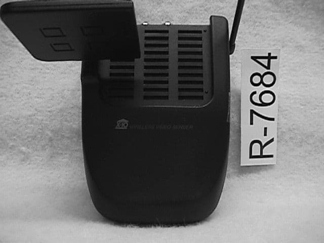
Click to zoom
Application Details
- Equipment Class
- CRR - Superregenerative Receiver
- Date of Grant
- Mar 15, 1999
- Application Purpose
- Original Equipment
- Date of Application
- Jan 12, 1999
- Frequency Range
- 310.00000000 - 310.00000000
- Company
- Authinx Inc.
- Country
- United States
Documents & Files
Document Text
Text extracted from the exhibit documents filed with the FCC. Open a document above to read the original.
Block Diagram
Left Audio Input Right Audio Input Video Input FM ModulatorFM ModulatorPre-emphasis 310MHz Receiver IR Driver DSS control output 310MHz 2.4GHz RFTransmitter 2.4GHz Patch Antenna 4-Channels Selector Block Diagram for Video Sender Transmitter (VT30A)
ID Label/Location Info
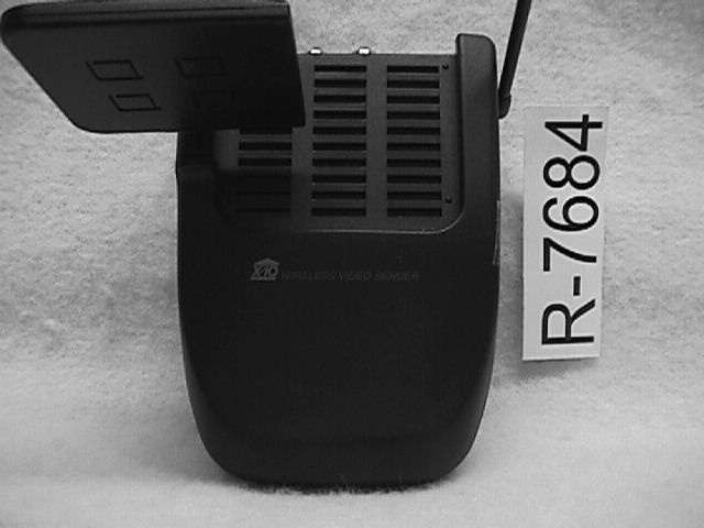
X-10 (USA) Inc., Closter, NJ 07624. Made in China THIS DEVICE COMPLIES WITH PART 15 OF THE FCC RULES. OPERATION IS SUBJECT TO THE FOLLOWING TWO CONDI- TIONS: (1) THIS DEVICE MAY NOT CAUSE HARMFUL INTER- FERENCE, AND (2) THIS DEVICE MUST ACCEPT ANY INTER- FERENCE RECEIVED, INCLUDING INTERFERENCE THAT MAY CAUSE UNDESIRED OPERATION. Model No. VT30A rating label 2: 1 2.4GHz Wireless Audio/Video Sender For use with Model VR30A 2.4 GHz Receiver, and Model PT30A plug-in power supply. Ratings: 12VDC, 200 mA max. For indoor use only. Refer to Owner's Manual for more information. Model No. VT30A FCC ID: B4SVT30A
Operational Description
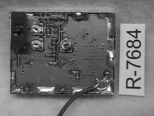
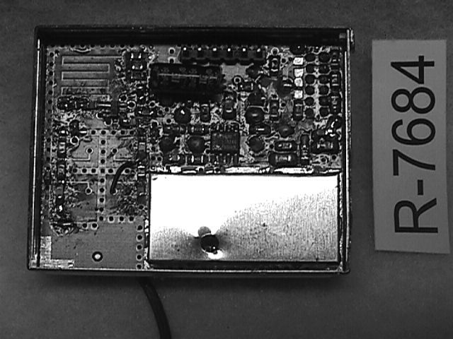
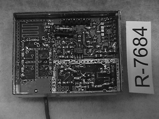
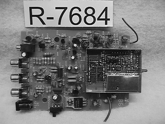
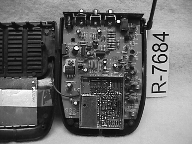
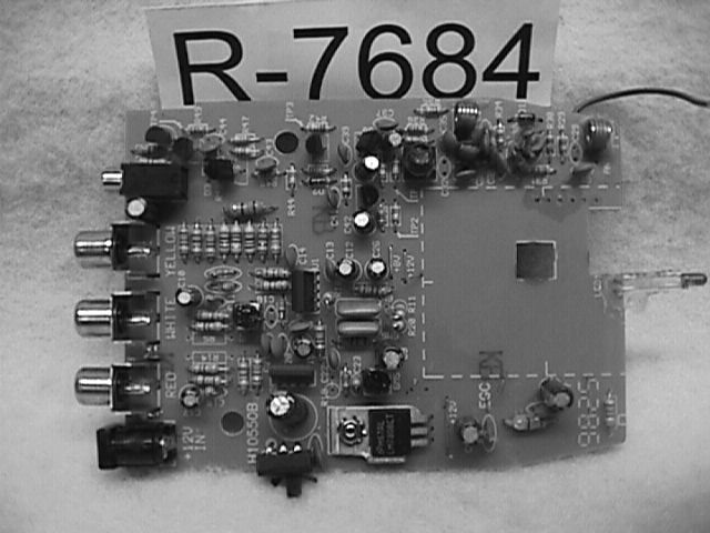
310 Mhz Superregenerative Receiver Operational Description The 310 MHz receiver receives a pulsed 310 MHz RF signal from a universal RCA remote control such as the model RCSAT (FCC ID: B4SRCSAT2). The signal is then converted to an Infrared format and sent to the IR extender jack on the Audio/Video Sender. A cable can then be attached to a RCA DSS receiver at the IR control Input. This signal is used to remotely change channels on some RCA DSS receivers.
Test Report
REPORT No. R-7684-1 FCC COMPLIANCE TEST REPORT ON X-10 (USA), Inc. 310MHz Superregenerative Receiver Model: VT30A FCC ID: B4SVT30A Customer Name:X-10 (USA), Inc. Customer P.O.:Verbal Test Method:ANSI C63.4:1992 Test Specification:FCC Rules & Regulations Part 15 Date of Report:January 11, 1999 RETLIF Test Report No.:R-7684-1 Test Engineer:T.J. Schneider Report Written By:R. Stremel Supervisor:R.J. Reitz Our letters and reports are for the exclusive use of the customer to whom they are addressed, and their communication to any other or the use of the name of RETLIF TESTING LABORATORIES must receive our prior written approval. Our letters and reports apply only to the sample tested and are not necessarily indicative of the qualities of apparently identical or similar products. The reports and letters and the name of RETLIF TESTING LABORATORIES or insignia are not to be used under any circumstances in advertising to the general public. REPORT No. R-7684-1 TABLE OF EXHIBITS Exhibit 1Installation and Operating Instructions per 2.1033(b)(3) Exhibit 2Technical Description per 2.1033(b)(4) Exhibit 3Block Diagram and Schematics per 2.1033(b)(5) Exhibit 4Report of Measurements - Receiver Portion - per 2.1033(b)(6) Exhibit 5Equipment Photographs and Label per 2.1033(b)(7) REPORT No. R-7684-1 EXHIBIT 1 Installation and Operating Instructions Para. 2.1033(b)(3) REPORT No. R-7684-1 EXHIBIT 2 Technical Description Para. 2.1033(b)(4) REPORT No. R-7684-1 Technical Report 2.1033(b)(4) Equipment Manufacturer X-10 Electronics Shenzhen Co. Ltd. X-10 Building Labour Industrial District Shenzhen, Xixiang, Bao An Guang Dong, China, 518102 FCC Identifier B4SVT30A Operating Instructions See Exhibit 1 Trade Name X-10 PowerHouse Model Number VT30A Additional Model Numbers and Trade Names Not Applicable REPORT No. R-7684-1 EXHIBIT 3 Block Diagram and Schematic Para. 2.1033(b)(5) REPORT No. R-7684-1 EXHIBIT 4 Report of Measurements Para. 2.1033(b)(6) REPORT No. R-7684-1 X-10 USA, Inc. 91 Ruckman Road Closter, NJ 07624 MANUFACTURER X-10 Electronics Shenzhen Co. Ltd. X-10 Building Labour Industrial District Shenzhen, Xixiang, Bao An Guang Dong, China, 518102 TEST SPECIFICATION:Part 15, Subpart B Certification TEST PROCEDURE: ANSI C63.4:1992 TEST SAMPLE DESCRIPTION BRANDNAME:X-10 PowerHouseMODEL:VT30A TYPE:310MHz Superregenerative Receiver POWER REQUIREMENTS:12 VDC FREQUENCY RANGE:310MHz TESTS PERFORMED Para. 15.107(a), Conducted Emissions, Receiver Locked Para. 15.109(a), Radiated Emissions, Receiver Locked I HEREBY CERTIFY THAT: The measurements shown here were in accordance with the procedure indicated and that the energy emitted by this equipment was found to be within the limits applicable. I assume full responsibility for the accuracy and completeness of these measurements and vouch for the qualifications of all persons taking them. I FURTHER CERTIFY THAT: On the basis of the measurements made, the device tested is capable of operation in compliance with the requirements of Part 15 of the FCC Rules under normal use and maintenance. SIGNPRINT Thomas J. Schneider TITLE EMC Test Engineer REPORT No. R-7684-1 Test Procedures Used The test procedures used for all testing follow the guidelines specified in the applicable FCC specification and general industry practices. Although test procedures may sometimes have to be modified to address the needs of specific test samples, the following forms the basis for all testing programs: Conducted Emissions - All testing was performed with the test sample placed 80cm above a 2.5 x 3M ground plane and 1 meter from any other grounded surface. The power cord of the test sample was connected to the Line Impedance Stabilization Networks, which in turn, had their cases mounted to the ground plane. With the equipment connected as stated, an EMI meter or spectrum analyzer was connected to the LISN and the conducted emissions were measured over the frequency range of 450KHz to 30MHz, in turn on each of the input power leads. Care was taken during testing to relocate all system components and cabling in an effort to maximize the emissions from the EUT. Radiated Emissions - Radiated emissions testing was performed on an FCC listed 3 meter open field test site over the frequency range of 30MHz to 2000MHz. Prior to open field testing, pre-scan testing was performed inside of a shielded enclosure in order to obtain a spectrum signature of the unit and to use the data obtained as a guideline for open field testing. When the test sample is taken to the open field tests site, it is placed on a one meter high wooden turntable. A spectrum analyzer or EMI meter is then connected to either the biconical or log periodic anenna, depending on frequency range being scanned. The antenna is mounted on a remote controlled four meter antenna mast. The frequency range was then scanned and each measurement taken was maximized by performing the following: (1) Raising and lowering the measurement antenna. (2) Rotating the measurement antenna to both the horizontal and vertical polarizations. (3) Tuning the measurement antenna to the frequency of measurement. (4) Rotating the test sample, and (5) Relocating all interconnecting and input power cables. In the event that testing was extended above or below the frequency range of 30MHz to 1000MHz, loop antennas were used for all measurements below 30MHz and horn antennas were used for all measurements above 1000MHz. REPORT No. R-7684-1 REPORT OF MEASUREMENTS RADIATED EMISSIONS PARA. 15.109(a) REPORT No. R-7684-1 TEST PERFORMEDMODEL NUMBER Radiated EmissionsX-10 PowerHouse FCC Part 15/B/BVT30A E.U.T. CONFIGURATION JUSTIFICATION The test sample, with cables connected, was arranged on the test stand. This configuration was rotated and all power cables were relocated in order to maximize the emissions from the E.U.T. The test antenna was raised, lowered and both vertically and horizontally polarized to further maximize the emissions (polarization is dependent on the frequ…
Text truncated - open the document above for the full version.
Test Report
Retlif Testing Laboratories R Retlif Job Number R-7684-1 Data Sheet 1 of 1 Test Method: FCC Part 15 Radiated Emissions, 30 MHz to 2 GHz Customer: X-10 (USA) Inc. Job No. R-7684-1 Test Sample: Superregenerative Receiver FCC ID: B4SVT30A Model No.: VT30A Serial No. N/A Operating Mode: Continuously receiving 310 MHz Signal Technician: Dennis Cortes Date: December 21, 1998 Notes: Detector Function: Quasi-Peak (Peak above 1 GHz)Temp: 11CHumidity: 81% Test Distance: 3 meters Test Freq. Antenna Position Turntable Position Meter Reading Correction Factor Corrected Reading Converted Reading QP Limit MHz(H/V) –HeightDegreesdBuVdBdBuV/muV/muV/m 30.0100 || VV 88.00100 88.00150 || VV 216.00150 216.00200 || V| 305.50V-1.522540.3-4.136.264.6| 307.00V-1.522540.7-4.036.768.4| 308.50V-1.522542.1-4.038.180.4| 311.50V-1.522544.0-3.840.2102.3| 313.10V-1.522543.6-3.839.897.7| 314.60V-1.522542.4-3.738.786.1| 316.10V-1.522540.8-3.637.272.4| 317.60V-1.522538.3-3.634.754.3| 932.90V-1.022530.47.537.978.5| 934.50V-1.022530.67.638.281.3| 935.90V-1.022530.97.738.685.1| 938.90V-1.022531.07.838.887.1| || VV 960.00200 960.00500 || V| 1204.80V-1.222549.9-6.443.8154.9| 1269.00V-1.522550.8-3.647.2229.1| || || VV 2000.00500 The frequency range was scanned form 30 MHz to 24 GHz. All emissions not recorded were more then 20dB below the specified limit. Emission observed from the EUT do not exceed the specified limit.
Contact Information
Applicant
Shane Houshmand(Chief Operating Officer)
Technical Contact
Retlif Testing LaboratoriesThomas J Schneider
[email protected]516-737-1500
795 Marconi Avenue · Ronkonkoma, New York · United States
Test Firm
Retlif Testing LaboratoriesMichael Bozza
Technical Specifications
| # | Rule Parts | Frequency Range | Power Output |
|---|---|---|---|
| 1 | 15B | 310 MHz - 310 MHz | - |
Other Applications from Authinx Inc.

B4SXC35A
Jun 16, 2011Wireless Color Camera
Equipment Class
DXX - Part 15 Low Power Communication Device Transmitter
B4SVT50
Jun 16, 2011Wireless Audio/Video System
Equipment Class
DXX - Part 15 Low Power Communication Device Transmitter
B4SVR50
Jun 13, 2011Wireless Audio/Video Receiver
Equipment Class
DSC - Part 15 Security/Remote Control Transmitter
B4S-XC30A
Jun 07, 2011Wireless Color Camera
Equipment Class
DXX - Part 15 Low Power Communication Device Transmitter
B4SIR34A
Aug 01, 2010Remote Control Transmitter
Equipment Class
DSC - Part 15 Security/Remote Control Transmitter