B4SVT37AVGA Video Sender
Authinx Inc.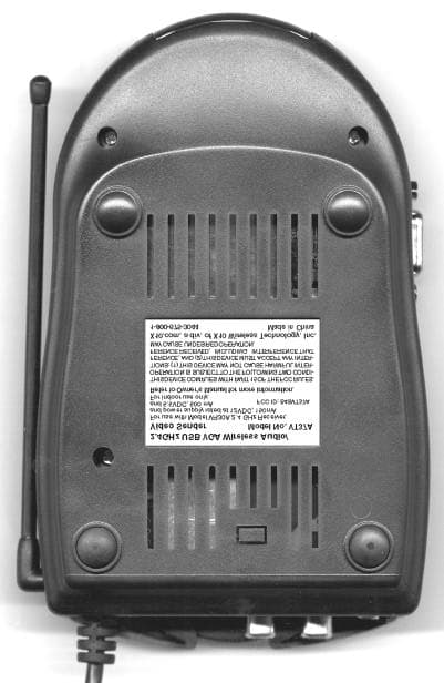
Click to zoom
Application Details
- Equipment Class
- DXX - Part 15 Low Power Communication Device Transmitter
- Date of Grant
- Jul 08, 2001
- Application Purpose
- Original Equipment
- Date of Application
- Jul 08, 2001
- Equipment Note
- VGA Video Sender
- Frequency Range
- 2410.00000000 - 2472.00000000
- Company
- Authinx Inc.
- Country
- United States
Documents & Files
Document Text
Text extracted from the exhibit documents filed with the FCC. Open a document above to read the original.
Users Manual
OWNER'S MANUALVGA Video SenderM ODEL VK72A ( INCLUDES VT37A USB S ENDER AND VR30A R ECEIVER ) VT37A VR30A 3 2 FCC C AUTION THIS DEVICE COMPLIES WITH PART 15 OF THE FCC RULES.OPERATION IS SUBJECT TO THE FOLLOWING TWO CONDITIONS:(1)THIS DEVICE MAY NOT CAUSE HARMFUL INTERFERENCE, AND(2)THIS DEVICE MUST ACCEPT ANY INTERFERENCE RECEIVED, INCLUDING INTERFERENCE THAT MAY CAUSE UNDESIRED OPERATION. This equipment generates and uses radio frequency energy, and if not installed andused properly, that is, in strict accordance with the manufacturers instructions, it maycause interference to radio and television reception. It has been type tested and foundto comply with the limits for remote control devices in accordance with thespecifications in Sub-Parts B and C of Part 15 of FCC Rules, which are designed toprovide reasonable protection against such interference in a residential installation.However, there is no guarantee that interference will not occur in a particularinstallation. If this equipment does cause interference to radio or television reception,which can be determined by unplugging the equipment, try to correct the interfer ence by one or more of the following measures.• Reorient the antenna of the radio/TV experiencing the interference.• Relocate the equipment with respect to the radio/TV.• Move the equipment away from the radio/TV.• Plug the equipment into an outlet on a different electrical circuit from the radio/TV experiencing the interference. • If necessary, consult your local Dealer for additional suggestions.NOTE: Modifications to this product will void the user's authority to operate this equipment. I NTRODUCTION Your Wireless VGA Video Sender kit consists of a Sender base unitwhich connects to the audio out jack, the VGA output, and the USBport on your PC, and a Receiver unit which you connect to your TV.The Sender converts the audio signal from your PC's sound card,and the VGA video from your PC's video card into a radiofrequency (RF) signal and transmits it (even through walls) to theReceiver unit. The Receiver converts the signals back to theiroriginal form and passes them to your TV. The USB port allows youto use the VGA sender with X10 RF remote controls, (soldseparately) to control your PC wirelessly. WARNING: To reduce the risk of fire or electric shock, do not expose this productto rain or moisture. SYSTEM REQUIREMENTS To use the VGA Video Sender system your PC must have a USBport, a VGA out port (that normally connects to your monitor) and asound card with mono or stereo output. Max resolution is 1024 x768, but 800 x 600 is recommended. 5 4 S ENDER (T OP V IEW ) R ECEIVER (B OTTOM V IEW ) 2.4 GHz Channel Switch 2.4 GHz Channel Switch C ONTROLS AND C ONNECTIONS S ENDER (S IDE V IEW ) VGA In C ONTENTS C ONTROLS AND C ONNECTIONS ................................................... 5 S ENDER .......................................................................... 6 R ECEIVER ........................................................................ 7 B EFORE YOU START ................................................................. 8 C ONNECTING U P .................................................................. 9 H OOKING UP THE S ENDER .................................................... 9 H OOKING UP THE R ECEIVER ................................................. 10 F INE TUNING YOUR S YSTEM .................................................... 12 T ROUBLESHOOTING ............................................................... 13 USB port connector 7 6 R ECEIVER 2.4 GHz Video Antenna TV Output Connector A/V Input Jacks Power Supply Jack 2.4 GHz Channel Switch (on bottom) TV Channel Switch (on bottom) ON-OFF Switch (on side) S ENDER 310 MHz Antenna for use with UR83A remote Audio Input Jacks Power Supply Jack 2.4 GHz Video Antenna ON-OFF Switch (on side) 2.4 GHz Channel Switch USB port connector 9 8 C ONNECTING U P H OOKING UP THE VGA S ENDER 1. Connect the jack on the audio cable (supplied) to the audio out jack on your PC sound card. 2. Connect the red RCA plug to the socket labelled AUDIO RIGHT and the white RCA plug to the jack labeled AUDIO LEFT on theVGA Video Sender. 3. Connect the VGA cables as show below so that the VGA out from your PC connects to the VGA input on the VT37A and then alsopasses to the VGA input on your monitor. 4. Set the channel switch (on the TOP of the unit) to channel A (to the RIGHT). 5. Plug the VGA Video Sender's Power Supply (the larger of the two power supplies) into a convenient 120 volt wall outlet andplug its jack into the VGA Video Sender. 6. Position the VGA Video Sender in a convenient location and orient the antenna so that the flat side points in the direction of theroom where you will be installing the Video Receiver. P Before you start installing your VGA System it is recommended thatyou read this entire owner's manual. This will familiarize you withthe basic hardware installation. Then install the hardware (do NOTconnect the USB connector yet). You will be able to see a picturefrom your PC on our TV screen. You can then visit www.x10.com/software and download the "Boom" program, which will give youcontrol over what is sent from your PC to your TV.Install the Boom software (do NOT plug the VGA sender into yourUSB port yet). When instructed to do so by the Boom installationprogram, plug the VGA sender into your USB port. Windows willtell you it has found new hardware and will automatically install theX10 USB driver for the VGA sender. B EFORE Y OU S TART USB port connecter (do notconnect until you install theBoom software) * If your PC does not have a USB port you won't beable to use the remote control features of the UR83A. 11 10 I F YOUR SECOND TV IS ALREADY HOOKED UP TO A DBS R ECEIVER OR OTHER A/V DEVICE If your DBS Receiver or other A/Vcomponent is connected to the TV usingA/V cables, you can connect the VideoReceiver to the free LINE IN jacks onthe component. If there are no LINE INjacks, you will need to use a TVante…
Text truncated - open the document above for the full version.
ID Label/Location Info
X10.com, a div. of X10 Wireless Technology, Inc. 1-800-675-3044 THIS DEVICE COMPLIES WITH PART 15 OF THE FCC RULES. OPERATION IS SUBJECT TO THE FOLLOWING TWO CONDI- TIONS: (1) THIS DEVICE MAY NOT CAUSE HARMFUL INTER- FERENCE, AND (2) THIS DEVICE MUST ACCEPT ANY INTER- FERENCE RECEIVED, INCLUDING INTERFERENCE THAT MAY CAUSE UNDESIRED OPERATION. Model No. VT37A rating label 2: 1 6/4/01 2.4GHz USB VGA Wireless Audio/ Video Sender Model No. VT37A FCC ID: B4SVT37A Made in China S1 (for video transmitter) - 12VDC, 150mA S2 (for VGA converter) - 5.5VDC, 500mA For use with Model VR30A 2.4 GHz Receiver, and power supply rated at 12VDC, 150mA and 5.5VDC, 500 mA For indoor use only. Refer to Owner's Manual for more information.
Operational Description
VT37A Operational description: Left and right audio signals are FM modulated. The VGA video output from a PC is passed through, unmodified, to the PC's monitor, and is also converted to composite video, which after pre-emphasis, is combined with the FM modulated audio signals and passed to the 2.4 GHz transmitter. The 2.4 GHz transmitter has a 4 channel selector switch to transmit the video and audio signals at either 2.411 GHz, 2.434 GHz, 2.453 GHz, or 2.473 GHz, with a bandwidth of 18 MHz, via a patch antenna. The VT37A also includes a 310 MHz superregenerative receiver, which decodes RF transmissions from a remote control (not part of this report) via a microprocessor and passes them to a PC's USB port. This enables remote control of PC functions so that the user can remotely control what PC content is transmitted via 2.4 GHz from the PC to a separate 2.4 GHz receiver (not part of this report) which is connected to the user's TV. This lets the user watch and hear PC content on their TV.
Schematics
1 2 3 4 5 6 78 ABCD 8 7 6 5 4 3 2 1 D CBA VGA SENDER Main Board VT37A 11 Title: Revision: Number: of Sheet Error : X-10.BMP File Not Found Date: 24-May-2001 Drawn By: SYSTEM X-10 LIMITED Ian Wong File Name: J1AUDIO L R310 3K9 R30833K R3027K5 R30722K C30722 湩 <WHITE> To Transmitter J2AUDIO R C3064700pF C305100pF C309100p R3066K8 R305820R R300220R C30822 湩 <RED> SW1SLIDE SWITCH C1 100 湩 R3013K3 R101K2 ON OFF 25V LED1RED 3MM Module +8V Q301BBY-40 T300IFT 6M C31010nF C303100pF R3033K3 Q3003904 C301100pFC30027pF R3041K5 R1139K C31151p <YELLOW> +12V 310 RF Receiver Daughter Board R1100R C4100u +12V Out Ground +8V In Video Out Left Audio Out Right Audio Out 10V C2 470u C3 470u Vin COM Vout BA033T U2 3V3 Vin COM Vout 5V Regulator U3 C6 100uF 5V J412V / 5V DC CX2150P CY2 1N5 CX1 150P CY1 1N5 3V3 GND VIDEO GND D3 1N4001 C9 470u CX10.1u CX20.1u CX3 0.1u C7 100uF CX4 0.1u RX1K5 +5V RF IND-D+ R2 560R R3 560R SCLSDA C8100N RF IN CY7C63723 CAMTX1H2x.sch-1 - Wed Mar 21 15:59:52 2001 VT37A 1 2 3 4 ABCD 4 3 2 1 D CBA 1 Protel Technology Inc. 1 851001H11233 21-Mar-2001 18:44:21 TitleSize: Number: Date: File: Revision: Sheet of Time: A4 RF Board for VT37A C18P C31N C40.5P C17100N C21N ANT L1 4T5R L21uH R120K R5 3K9 R70R R18 10R R26K8 Q1 BFT25 L3 C56p C15 * C6 47p Q2H10 R3 2K R19 0R R4 3K9 +3V3 R62K7 L41uH C8 470P Vin COM Vout U1 HT1033 C92p7 R810K R910K R11100KR12100K R132M2 R14100K C10 4N7 C11 100N +3V3 +5V C14 100N RF OUT C72p U2 LM358 C1247P U2 LM358 C13100N 32 1 84 5 7 6
Test Report
APPLICANT X-10 USA, Inc. 91 Ruckman Road Closter, NJ 07624 MANUFACTURER X-10 Electronics Shenzhen Co. Ltd. X-10 Building Labour Industrial District Shenzhen, Xixiang, Bao An Guang Dong, China, 518102 TEST SPECIFICATION: FCC Rules and Regulations Part 15, Subpart C TEST PROCEDURE: ANSI C63.4:1992 TEST SAMPLE DESCRIPTION BRANDNAME: X-10 MODEL: VT37A FCC ID: B4SVT37A TYPE: 2.4 GHz FM Transmitter FREQUENCY RANGE: 2410 to 2472 MHZ POWER REQUIREMENTS: 5 VDC and 12 VDC derived from an AC Adapter, Model, NO-HKSD-01104, and Manufactured by Hon-Kwang TESTS PERFORMED - 15.249(a) Radiated Emissions, Fundamental and Harmonics - 15.294(c) Occupied Bandwidth - 15.249(c)/15.209 Radiated Emissions, Spurious Case - 15.207(a) Conducted Emissions REPORT OF MEASUREMENTS Applicant: X-10 (USA), Inc. Device: 2.4 GHz Transmitter FCC ID: B4SVT37A Power Requirements: 5 VDC and 12 VDC derived from an AC Adapter, Model, NO-HKSD-01104, and Manufactured by Hon-Kwang Applicable Rule Section: Part 15, Subpart C, Section 15.249 TEST RESULTS 15.207(a): The radio frequency voltage that was conducted back on to the AC power line on any frequency/frequencies within the bandwidth of 450kHz to 30MHz did not exceed 250 microvolts. 15.249(a): The unit operates in the 2.4 to 2.4835 GHz band at 4 frequencies as follows: 1) Channel A, 2.410 GHz 2) Channel B, 2.433 GHz 3) Channel C, 2.453 GHz 4) Channel D, 2.472 GHz Field strength readings were taken at 3 frequencies (low, middle and high) because the device operates over a range greater than 10 MHz The field strength of the fundamental did not exceed 50 milliV/M AVERAGE. The field strength of the harmonics did not exceed 500 microV/M AVERAGE. 15.249(b): Field strength readings were taken at three meters unless otherwise noted. 15.249(c): Emissions radiated outside band edges were greater than 50 dB below the specified the level of the fundamental or met the general radiated emission requirements of 15.209(a), whichever provided the lesser attenuation. 15.249(d): The peak field strength of any emission did not exceed the maximum permitted average field strength by more than 20dB under any condition of modulation. EXHIBIT 4 Radiated Emissions, Fundamental & Harmonics Para. 15.249(a) (See separate e-file attachments named REFundHarm.doc) EXHIBIT 4 Spurious Emissions Para. 15.249(c) (See separate e-file attachment RESpur.doc) EXHIBIT 4 Occupied Bandwidth Para. 15.249(c) (See separate e-file attachment named Occbw.pdf) EXHIBIT 4 Conducted Emissions Para. 15.207(a) (See separate e-file attachment named CEdata.pdf) EQUIPMENT LIST FCC 15.249 Compliance Testing EN Type Manufacturer Description Model No. Cal Date Due Date 078 LISN Solar Electronics 10 kHz - 30 MHz 8028-50-TS24BNC 5/2/01 5/2/02 091 Shielded Enclosure Retlif 10 kHz - 1 GHz Room 6 7/21/00 7/21/01 128C Double Ridge Guide Eaton Corporation 1 GHz - 18 GHz 96001 9/18/00 9/18/01 129E High Gain Horn Antenna Microlab/FXR 18 GHz - 26.5 GHz K638A 9/18/00 9/18/01 133 Broadband Pre-Amplifier Electro-Metrics 10 kHz - 1 GHz, 26dB BPA-1000 6/13/00 6/13/01 141A Graphics Plotter Hewlett Packard N/A 7470A 3/5/01 3/5/02 202 Transient Limiter Hewlett Packard .009 MHz - 200 MHz 11947A 7/24/00 7/24/01 206B 6.0 dB Attenuator Texscan 0 - 1.0 GHz FP-50 - 6 dB 6/13/00 6/13/01 420 Amplifier Hewlett Packard 2.0 GHz - 18 GHz 11975A 9/29/00 9/29/01 421 Harmonic Mixer Hewlett Packard 18 GHz - 26.5 GHz 11970K 9/29/00 9/29/01 456 LISN Solar Electronics DC - 60 Hz 9409-50-R-24 7/26/00 7/26/01 513 LISN Solar Electronics 10 kHz - 30 MHz 8028-50-TS24BNC 5/1/01 5/1/02 523 Biconilog Electro-Mechanics 26 - 2000 MHz 3142B 6/8/00 6/8/01 543 Preamplifier Hewlett Packard 1.0 GHz - 26.5 GHz 8449B 6/16/99 6/16/01 617 Interference Analyzer Electro-Metrics 10 kHz - 1 GHz EMC-30 2/27/01 2/27/02 7016 EMC Analyzer Hewlett Packard 9kHz - 1.8GHz 8591EM 3/6/01 3/6/02 712 EMI Test Receiver Rohde & Schwarz 20 Hz - 26.5 GHz ESI26 3/1/00 7/1/01 Test Setup Photographs Test Setup Photographs Test Setup Photographs Test Setup Photographs Retlif Testing Laboratories R Data Sheet 1 of 6 Test Method: FCC Part 15 Subpart C Radiated Emissions, Fundamental & Harmonic Emissions Customer: X-10 USA Job No. R-9037-1 Test Sample: 2.4GHz FM Transmitter Paragraph: 15.249 Model No.: VT37A FCC ID: B4SVT37A Operating Mode: Continuously Transmitting a 2.410 GHz Signal. Channel A Technician: Peter Lananna Date: June 5, 2001 Notes: Test Distance: 3 Meters Detector: Peak, Unless otherwise specified Channel A Test Freq. Antenna Pol./Height EUT Orientation Meter Reading Correction Factor Corrected Reading Converted Reading Average Limit GHz (V/H)/Meters X / Y / Z dBuV dB dBuV/m uV/m uV/m 2.410 H / 2.3 X 80.9 3.0 83.9 15667.5 50000 | H / 2.3 Y 77.1 3.0 80.1 10115.8 | | H / 2.3 Z 76.4 3.0 79.4 9332.5 | | V / 2.3 X 78.9 3.0 81.9 12445.1 | | V / 2.0 Y 75.2 3.0 78.2 8128.3 | 2.410 V / 1.8 Z 78.4 3.0 81.4 11749.0 50000 4.820 H / 1.0 X 32.0 -4.1 27.9 24.8* 500 | H / 1.0 Y 32.0 -4.1 27.9 24.8* | | H / 1.0 Z 32.0 -4.1 27.9 24.8* | | V / 1.0 X 32.0 -4.1 27.9 24.8* | | V / 1.0 Y 32.0 -4.1 27.9 24.8* | 4.820 V / 1.0 Z 32.0 -4.1 27.9 24.8* 500 7.230 H / 1.0 X 32.0 0 -2.0 32.0 39.8* 500 | H / 1.0 Y 32.0 -2.0 30.0 31.6* | | H / 1.0 Z 32.0 -2.0 30.0 31.6* | | V / 1.0 X 32.0 -2.0 30.0 31.6* | | V / 1.0 Y 32.0 -2.0 30.0 31.6* | 7.230 V / 1.0 Z 32.0 -2.0 30.0 31.6* 500 9.640 H / 1.0 X 33.0 -1.9 31.1 35.9* 500 | H / 1.0 Y 33.0 -1.9 31.1 35.9* | | H / 1.0 Z 33.0 -1.9 31.1 35.9* | | V / 1.0 X 33.0 -1.9 31.1 35.9* | | V / 1.0 Y 33.0 -1.9 31.1 35.9* | 9.640 V / 1.0 Z 33.0 -1.9 31.1 35.9* 500 12.05 H / 1.0 X 33.0 3.8 36.8 69.2* 500 | H / 1.0 Y 33.0 3.8 36.8 69.2* | | H / 1.0 Z 33.0 3.8 36.8 69.2* | | V / 1.0 X 33.0 3.8 36.8 69.2* | | V / 1.0 Y 33.0 3.8 36.8 69.2* | 12.05 V / 1.0 Z 33.0 3.8 36.8 69.2* 500 The frequency range was scanned from 30 MHz to 25GHz. All emissions not recorded were more Than 10 dB below the specified limit. Emissions from the EUT do not exceed the specified limits. *=Noise Floor Measurements (Minimum system s…
Text truncated - open the document above for the full version.
Test Setup Photos
Test Setup Photographs Test Setup Photographs Test Setup Photographs
Contact Information
Applicant
Shane Houshmand(Chief Operating Officer)
Technical Contact
Retlif Testing LaboratoriesThomas J Schnieder
[email protected]1 631 737-1500
795 Marconi Avenue · Ronkonkoma, New York · United States
Non-Technical Contact
Retlif Testing LaboratoriesMichelle White
[email protected]1 631 737-1500
Test Firm
Retlif Testing LaboratoriesMichael Bozza
Technical Specifications
| # | Rule Parts | Frequency Range | Power Output |
|---|---|---|---|
| 1 | 15C | 2.41 GHz - 2.47 GHz | - |
Other Applications from Authinx Inc.

B4SXC35A
Jun 16, 2011Wireless Color Camera
Equipment Class
DXX - Part 15 Low Power Communication Device Transmitter
B4SVT50
Jun 16, 2011Wireless Audio/Video System
Equipment Class
DXX - Part 15 Low Power Communication Device Transmitter
B4SVR50
Jun 13, 2011Wireless Audio/Video Receiver
Equipment Class
DSC - Part 15 Security/Remote Control Transmitter
B4S-XC30A
Jun 07, 2011Wireless Color Camera
Equipment Class
DXX - Part 15 Low Power Communication Device Transmitter
B4SIR34A
Aug 01, 2010Remote Control Transmitter
Equipment Class
DSC - Part 15 Security/Remote Control Transmitter