B4SVT44AWIRELESS AUDIO/VIDEO SENDER w/ IR EXTENDER FEATURE
Authinx Inc.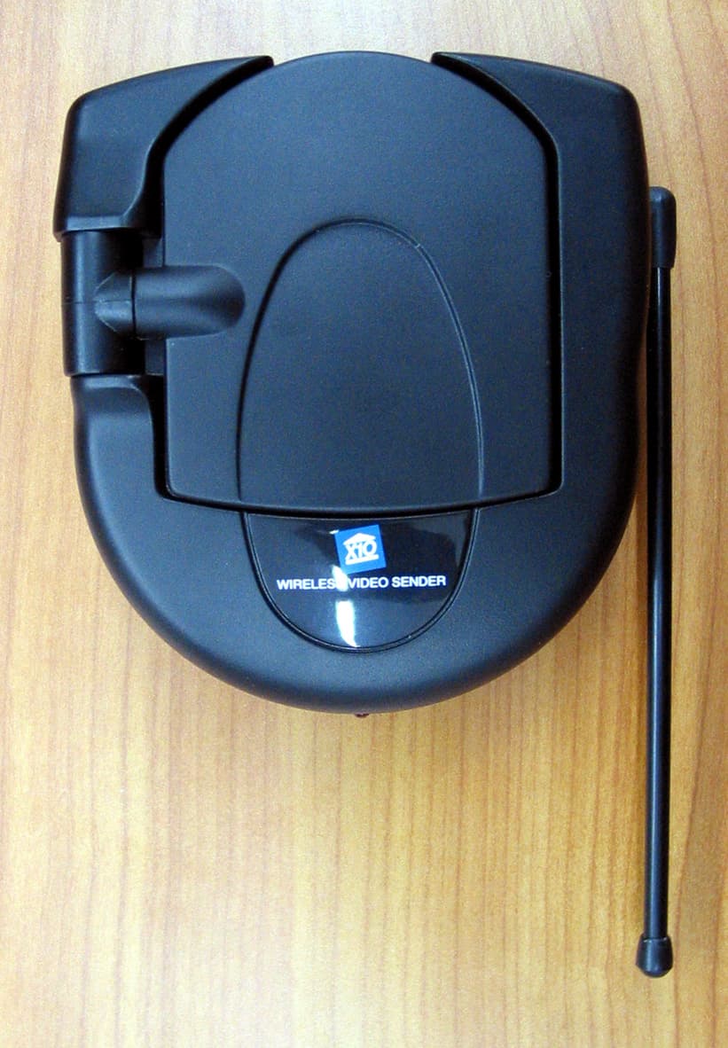
Click to zoom
Application Details
- Equipment Class
- DXX - Part 15 Low Power Communication Device Transmitter
- Date of Grant
- Dec 06, 2006
- Application Purpose
- Original Equipment
- Date of Application
- Dec 06, 2006
- Equipment Note
- WIRELESS AUDIO/VIDEO SENDER w/ IR EXTENDER FEATURE
- Frequency Range
- 2414.00000000 - 2468.00000000
- Company
- Authinx Inc.
- Country
- United States
Documents & Files
Document Text
Text extracted from the exhibit documents filed with the FCC. Open a document above to read the original.
Users Manual
X10.com, a division of X10 Wireless Technology, Inc. 3824 North 5th St., Suite C, North Las Vegas, NV 89032 Receiver Transmitter Point the flat antennasat each other OWNER’S MANUAL Model VK80A(includes VT44A Audio/Video Senderand VR40A Audio/Video Receiver) FCC CautionTHIS DEVICE COMPLIES WITH PART 15 OF THE FCC RULES.OPERATION IS SUBJECT TO THE FOLLOWING TWO CONDITIONS:(1) THIS DEVICE MAY NOT CAUSE HARMFUL INTERFERENCE, AND(2) THIS DEVICE MUST ACCEPT ANY INTERFERENCE RECEIVED, INCLUDING INTERFERENCE THAT MAY CAUSE UNDESIREDOPERATION. NOTE: Modifications to this product will void the user’s authority to operate this equipment.X10 Wireless Technology, Inc. Limited One Year WarrantyX10.com, a division of X10 Wireless Technology, Inc. (X10) warrants X10 productsto be free from defective material and workmanship for a period of one (1) year fromthe original date of purchase at retail. X10 agrees to repair or replace, at its solediscretion, a defective X10 product if returned to X10 within the warranty periodand with proof of purchase. If service is required under this warranty:Call 1-800-442-5065, visit www.x10.com, or e-mail [email protected] help or more information on setup, please visit:http://www.x10.com/supportVK80A-com_h14139-021106 Connect the Sender to power. Introduction: The Wireless Audio/Video Sender kit includes a Sender and a Receiver. You connect the Sender to the A/Voutputs on your primary TV (that your Satellite Receiver, VCR,DVD Player, Cable Box, etc., is connected to). You connectthe Receiver to a secondary TV in another room, up to 100feet away. The Sender converts the A/V signals from yourVCR, Cable Box, etc., into wireless signals and transmits them(even through walls) to the Receiver. The Receiver convertsthe wireless signals back to an A/V signal and feeds it througha cable to your TV’s A/V or COAX jacks. The IR control jacklets you remotely control the device connected to the Sender. Connect the Sender to your primary TV. Connecting the SenderPut your Sender in a convenient place near or on your primary TV.Plug its power supply into astandard wall outlet and the otherend into the Sender. Connect an audio/video cableto the audio and video jacks onthe Sender and to the audio and video OUT jacks on theTV you want to send thepicture and sound from. Useyellow for video and the redand white plugs for audio. If your TV does not have audioand video OUT jacks, and youhave a VCR or other A/Vcomponent connected to the TVusing A/V cables, you can connectthe VCR to the TV using aCOAX Cable, and connect theSender to the A/V OUT jacks on the VCR, etc. Turn on the Sender . Make sure the power switch on the Sender is set to “ON.” Turn on your primary TV and the DVD Player, VCR, etc.,connected to it, that you want to use as a source to transmit toyour secondary TV. Connect the Receiver to your secondary TV. Put your Receiver in a convenient place near or on yoursecondary TV. Plug its powersupply into a standard wall outletand the other end into theReceiver . Turn on the Receiver. Connect the Receiver to power. Connecting the ReceiverConnect an audio/video cable tothe audio and video jacks on theReceiver and to the audio and video IN jacks on your secondaryTV. Use yellow for video and thered and white plugs for audio. Oruse the COAX connector.If a VCR or other A/V componentis connected to the TV using A/Vcables, you can connect theReceiver to the free LINE IN jacks on the component. Make sure the power switch on the Receiver is set to “ON.” Turn on your secondary TV.Make sure you can see the appropriate picture from yourDVD Player, VCR, Satellite Receiver etc., on yourprimary TV that you connected the Sender to. Select the video input on your secondary TV. Use the Video orSelect buttons on your TV remote control, or try channel 0and then Channel Down. The same picture you see onyour primary TV should appear on your secondary TV. If you do not see any picture on your TV:Check that the Sender and the Receiver are on the same letterchannel (A, B, C, or D). The channel switch is on the bottom ofthe Receiver and on the top under the flip-up antenna on the Sender . TroubleshootingVerify that your connections to the TV are correct. Make sureyou are using the appropriate input mode for your TV, try pressingthe A-B button or Video button on your TV’s remote control tochange the input mode (consult your TV’s owner’s manual, ifnecessary). If the picture on your TV isn’t clear:First, adjust the antennas on the Sender and Receiver so thatthe side marked with four squares point towards each other.You can also try moving the Sender and/or Receiver to anotherlocation near the TV. Sometimes moving either unit just a footcan make a big difference.If the picture still doesn’t improve after adjusting the antennasand Sender/Receiver positions, try changing the channels onthe Sender and Receiver, making sure they are set to the sameletter (A, B, C, or D). Try different letter settings to see if thepicture improves.For more help with setup please visit:http://www.x10.com/support V V V V V ideo Sender ideo Sender ideo Sender ideo Sender ideo Sender W W W W W ir ir ir ir ir eless eless eless eless eless A A A A A udio/V udio/V udio/V udio/V udio/V ideo Extender ideo Extender ideo Extender ideo Extender ideo Extender System System System System System There is a power light onthe front of each unit.Check that the powerswitch on the side ofeach unit is ON. channelswitch ○○○○○ The IR control jack(See separate sheet).
Block Diagram
Left Audio Input Right Audio Input Video Input FM ModulatorFM ModulatorPre-emphasis 2.4GHz RFTransmitter 2.4GHz PatchAntenna 4-Channels Selector DSS control output IR Driver 310 Mhz Receiver Block Diagram for Video Sender Transmitter VT44A 310 Mhz
ID Label/Location Info
For use with A/V Receiver, Model VR40A. Ratings: 6VDC, 300 mA max. For indoor use only. See owner's manual for more information. THIS DEVICE COMPLIES WITH PART 15 OF THE FCC RULES. OPERATION IS SUBJECT TO THE FOLLOWING TWO CONDITIONS: (1) THIS DEVICE MAY NOT CAUSE HARMFUL INTERFERENCE, AND (2) THIS DEVICE MUST ACCEPT ANY INTERFERENCE RECEIVED, INCLUDING INTERFERENCE THAT MAY CAUSE UNDESIRED OPERATION. Model No. VT44A rating label 2: 1 11/20/06 2.4GHz Wireless Audio/Video Sender Model No. VT44A FCC ID: B4SVT44A IC: 1632A-VT44A Made in China X10.com, a Div. of X10 Wireless Technology, Inc., www.x10.com/support
Operational Description
VT44A Operational Description: The VT44A is a composite device that contains a 2.4 GHz FM transmitter and 310 MHz super regenerative receiver. The transmitter operates on one of 4 user selectable channels, A, B, C & D. Their respective frequencies are 2414 MHz, 2431 MHz, 2450 MHz and 2468 MHz. The VT44A takes the Left, Right and Composite Video Inputs and FM modulates the 2.4 GHz carrier. The signal is then transmitted via a patch antenna to theVR40A, 2.4 GHz receiver, where the process is reversed. The receiver receives a 310 MHz signal from VR40A and sends back an acknowledgement to VR40A.
Parts List/Tune Up Info
7/1/2006 17:54 SYSTEM XF MATERIAL PAGE 1 PART IDENTIFIER DESCRIPTIONQTY/ASSY REFERENCE ------------------------------------------------------------------------- VT44A-100=COMU VIDEO X'MITTER,310 NOPACK1 037006=10070B PVC FILM1 038010=10040-X LABEL-DATE CODE (WHITE)1 038020=12972RATING LABEL,VT44A1 183010=16300A RUBBER STAND2 183010=16390A ANTENNA COVER, VT30A1 183010=16400ANTENNA HOLDER, VT30A1 183010=16420A PLASTIC TUBE, VT30A1 183010=18000HINGE (A)1 183010=18010HINGE (B)1 183010=18020HINGE HOLDER1 183010=18240B SWITCH COVER1 183010=18670HINGE HOLDER (B)1 183010=19940DISK BOTTOM1 183010=19950DISK TOP1 185000=17130B BOTTOM CABINET1 185000=17148A TOP CABINET,BLACK1 186002=10410REAR TRIM LABEL,6V1 186003=10063ANTENNA LABEL (SENDER)1 201=1348001C TUBE-PVC 1.34MM TR0.04 220=00200180LED 3MM (RED DIFFUSED)1 LED1 363=22601000SINGLE SCREENED0.225 365000=10023HOT MELT GLUE, HE-38A1 391=60202040SCREW 2.3X8 PA, MS/ZP1 391=60203050SCREW-PPTT M2.6X6 MS/ZP1 391=60203060SCREW-PPTT M2.6X10 MS/ZP4 851001=11237PCB ASSY, (310)1 042010=10788A PCB1 074=60900004CAP-VAR 6P, SMD1 C16 076=10000002CAP-MCC 10P 5% NPO 08051 C5 076=10200007CAP-MCC 1N 10% X7R 08052 C3,17 076=10400007CAP-MCC 100N 10% X7R 08051 CX 076=10500016CAP-MCC 1U +8-2 Y5V 08052 C11,13 076=20900000CAP-MCC 2P .25P NPO 08051 C7 076=27900000CAP-MCC 2P7 .25P NPO 08051 C9 076=33100002CAP-MCC 330P 5% NPO 08053 C10,12,14 076=47000002CAP-MCC 47P 5% NPO 08051 C6 076=50800006CAP-MCC 0P5 .25P NPO 08051 C4 076=56100002CAP-MCC 560P 5% NPO 08051 C8 076=80900000CAP-MCC 8P .25P NPO 08051 C1 160=10900012INDUCTOR 1UH 10% SMD 06032 L2,4 162089=10023COIL 4T5R ID=2 WD=0.41 L1 162089=10036A COIL 3T5R ID=2, WD=0.41 L3 209=00000001TRS-NPN 2N3904 SMD3 Q3-5 209=00000009TRS-NPN BFT251 Q1 210117=10070TRS-NPN MPS H10 SMD1 Q2 211103=10000REGULATOR 78L051 240=10206011RES-CF 1K +/-5% 1/8W1 R17 241=00000000RES-TFC 0R 5% 1/10W 08052 R19,20 241=10000000RES-TFC 10R 5% 1/10W 08052 R7,18 241=10200000RES-TFC 1K 5% 1/10W 08053 R4,14,16 241=10300000RES-TFC 10K 5% 1/10W 08054 R8,9,11,12 241=10500000RES-TFC 1M 5% 1/10W 08052 R10,13 241=15100000RES-TFC 150R 5% 1/10W08051 R15 241=15200000RES-TFC 1K5 5% 1/10W 08051 R6 241=22300000RES-TFC 22K 5% 1/10W 08051 R1 241=39200000RES-TFC 3K9 5% 1/10W 08051 R3 241=47200000RES-TFC 4K7 5% 1/10W 08051 R2 241=91200000RES-TFC 9K1 5% 1/10W 08051 R5 358=60821001WIRE-JUMPER D=0.6MM3 851001=11784ANTENNA PCB ASSY1 042010=11131B PCB ANT. FR4 49X49X1.6MM1 363=00000031A COAXIAL RG178B/U 160MM1 851001=12575PCB ASSY 2.4G TX MODULE1 042010=11677A PCB, 2.4G TX1 076=10000022CAP-MCC 10P .25P COG 04025 C1,3,7,8,26 076=10100024CAP-MCC 100PF 5% COG 04021 C4 076=10400028CAP-MCC 100N 10% X7R 04024 C24,100,102,103 076=10500028CAP-MCC 1U 10% X7R 04025 C12-15,39 076=10600016CAP-MCC 10U +8-2 Y5V 08052 C35,36 076=10900022CAP-MCC 1P .25P COG 04021 C2 076=15300028CAP-MCC 15N 10% X7R 04021 C20 076=18000024CAP-MCC 18P 5% COG 04022 C51,53 076=22500031CAP-MCC 2U2 +8-2 Y5V 06032 C16,17 076=33000024CAP-MCC 33P 5% COG 04022 C22,23 076=47000024CAP-MCC 47P 5% COG 04021 C9 076=47300028CAP-MCC 47N 10% X7R 04023 C96-98 076=47400028CAP-MCC 470N 10% X7R 04021 C21 076=47500031CAP-MCC 4U7 +8-2 Y5V 06033 C18,19,25 076=56100028CAP-MCC 560P 10% X7R 04022 C31,32 076=56900022CAP-MCC 5P6 .25P COG 04022 C40,41 076=68100028CAP-MCC 680P 10% X7R 04021 C10 076=82000024CAP-MCC 82P 5% COG 04021 C11 076=82100028CAP-MCC 820P 10% X7R 04022 C5,6 080=00000048CRYSTAL 8MHZ HC-49/S1 Y1 110=00000015MULTILAYER LF2012 2400AC T1F1 138001=100545 WAY PIN HEADER 2.54MM1 P2 138001=100556 WAY PIN HEADER 2.54MM1 P1 160=27900019INDUCTOR 2N7H 5% 0402 SM D1L3 160=47600019INDUCTOR 4N7H 5% 0402 SM D1L2 160=82800012INDUCTOR 820NH 10%0603SM D2 L4,5 160=82900019INDUCTOR 8N2H 5% 0402 SM D1L1 211328=10382IC RTC6701 (QFN32)1 I1 241=00000006RES-TFC 0R 5% 1/16W 04025 L6,R1,5,25,34 241=10300006RES-TFC 10K 5% 1/16W 04027 R19,20,30,33-36 241=10400006RES-TFC 100K 5% 1/16W04023 R22,31,32 241=11100006RES-TFC 110R 5% 1/16W04021 R21 241=12200006RES-TFC 1K2 5% 1/16W 04022 R14,15 241=20300006RES-TFC 20K 5% 1/16W 04025 R8-12 241=39000006RES-TFC 39R 5% 1/16W 04021 R2 241=51300006RES-TFC 51K 5% 1/16W 04022 R17,18 241=68100006RES-TFC 680R 5% 1/16W04022 R7,26 241=75000006RES-TFC 75R 5% 1/16W 04022 R13,16 241=75100006RES-TFC 750R 5% 1/16W04022 R27,28 241=82300006RES-TFC 82K 5% 1/16W 04022 R50,52 403041=10117METAL BOX (A)1 851001=12747PCB ASSY, MAIN1 042010=11713B PCB1 057=10000018CAP-E 10U 20% 25V1 C6 057=10100002CAP-E 100U 20% 25V1 C7 057=10100053CAP-E 100U 20% 10V2 C4,5 076=10400014CAP-MCC 100N 10% X7R 06032 C8,9 076=22300014CAP-MCC 22N 10% X7R 06031 C2 149001=100203.5MM PCB MT MONO JACK1 J5 149=00000011SOCKET RCA PCB-MT (YELLOW1J3 149=00000020SOCKET RCA PCB-MT (RED)1 J2 149=00000021SOCKET RCA PCB-MT (WHITE)1J1 149=000000222.5MM DC JACK1 209=00000018TRS-NPN BC817-40 (SOT-23)1 Q1 210=00000000TRS-PNP 2N3906 SMD1 Q2 211103=10026LOW DROPOUT REG,1117-3V31 REG1 212107=10000DIODE-SI 1N41481 D1 212107=10002DIODE-SI 1N40041 D2 240=12206011RES-CF 1K2 +/-5% 1/8W1 R1 241=00000003RES-TFC 0R 5% 1/10W 06032 241=10200003RES-TFC 1K 5% 1/10W 06031 R10 241=10300003RES-TFC 10K 5% 1/10W 06031 R3 241=10400003RES-TFC 100K 5% 1/10W06031 R2 241=15200003RES-TFC 1K5 5% 1/10W 06031 R4 241=33100003RES-TFC 330R 5% 1/10W06031 R5 241=68000003RES-TFC 68R 5% 1/10W 06031 R6 283=00000003SLIDE-SW SS12F21 (1P2T)1 SW1 283=00000017SLIDE SW 2P4T (SS-24D02)1 SW3 358=60821001WIRE-JUMPER D=0.6MM6
Schematics
1 2 3 4 56 ABCD 6 5 4 3 2 1 D CBA Title Number Revision Size B Date: 7-Nov-2006 Sheet of File: D:\JOSEPH\SCH\VS\NEWVTA.SCH Drawn By: J3 YELLOW J2 RED J1 WHITE VIDEO AUDIO RAUDIO L TO 2.4G Module C7100uF/25V SW1SW-SLIDE J4DC JACK +3.3V IN GND +6V R10 1K Q1BC337 R2100K R310K D1 4148 C2 22nF Q29015 R70R J7 PHONEJACK C610u R41K5 R5330R R668R +5V 25V +6V 310/433.92MHz RF Receiver Daughter Board D14001 VI G VO REG1H1117/3.3V C4 100U LED R11K2 C8 100N C9 100N C1100uF 11 22 33 44 D D C C B B A A 1 SYS TEM X -10 H .K. LTD. 1 AV TRANSMITTER H1 16 77 -1 20 06 042 5D: \7 kam\10 WORK\ 2G 4\RW6 7 s eries-X T\6 7 T x\H 11 677 -1.SCHD OC Ti tl eSize: No: Dat e:File: Revision:Sheet of A4 Cann ot open fil e E: \D ocument s an d Sett in gs\ cheng chi a\ My 22-Jun-06 10 KR20 47 0n F C21 10 0n F C24 33 pFC23 8MHz 08 0-0 000 004 8 Y1 33 pFC22 SPI_SE 10 KR30 10 K R33 10 K R34 10 K R35 CH0CH1CH2 D_3.3V 4. 7uFC25 3.3V 56 0pC32 20 K R11 1KR7 20 KR12 75 0R2810 uF C36 Au di o Rig ht IN 51 K R18 1u FC15 2. 2uFC17 10 0K R31 1u FC39 3.3V VT 20 KR9 75 0R2710 uF C35 51 K R17 1u FC14 10 0K R32 56 0pC31 20 K R8 1KR26 2. 2uFC16 1u FC12 1. 2K R14 75 RR13 4. 7uFC19 82 0p FC6 10 KR19 75 RR16 20 KR10 0RR5 1. 2KR15 10 0p F C4 47 pF C9 68 0p F C10 82 pC11 82 0p F C5 82 0n H 06 03 L5 82 0n H 06 03 L4 VT Vi deo 10 0KR22 15 nFC20 11 0RR21 1u FC13 4. 7uF C18 3.3V 3.3V 2. 7nHL3 4. 7nHL2 1p FC2 10 pFC1 39R2 8. 2nHL1 10 pFC3 3.3V AU DIO L EFT IN VCOVDD 1 VT 2 GND 3 CP 4 AVT2 5 ACP2 6 AOUT2 7 AVDD2 8 AOUT1 9 NC 10 AVT1 11 ACP1 12 AVDD1 13 VDD 14 SPI_SE 15 BCR 16 RE G1 D8 17 PD_REG1D8 18 XTAL1 19 XTAL2 20 VDD33 21 SPICLK/CS0 22 SPILE/CS1 23 SPIDATA/CS2 24 BX 25 SYNVSS 26 RFGND2 27 PAOUT2 28 PAOUT1 29 RFGND1 30 PAVDD 31 NC 32 RTC6701A 21 132 8=10 382 U1 10 0nC103 0RL6 +V D_3.3V 3.3V 10 0nC102 NP 10nF C101 IN 1 GND 2 EN 3 BP 4 OUT 5 U2 VID EOALAR 123456 CON7P1 RFOUT 47 nFC96 47 n C97 47 nFC98 1234567 CON7P2 BX CH0CH1CH2 +V 10 pFC26 10 pFC810 pFC7 BX RFOUT 0RR1 6.5M 6M WHITE RED 10 K R36 1u FC34 0R R25 18 pF C51 18 pFC53 +5V NPC27 1 3 2 LF2 012 -B2R4FAA 11 0-0 000 001 5 F1 11 677 A -A3 Date By Detail KAM 20 060 605 Ass'y: 8510 01=1 257 5 2G4 TX - RT A 011B 1 01C 1 10D 111 US/EUR2414 M2432 M2450 M2468 M Ch CS0-2 AUS 2414 M2432 M2450 M 5p 6C40 5p 6C41 82 KR52 82 KR50 0RR34
Test Report
Retlif Testing Laboratories, Test Report R-11708-1, X10 (USA), FCC ID: B4SVT44A Page 1 of 34 Technical Information APPLICANT MANUFACTURER Name: X10 (USA), Inc. Name: X-10 Electronics (Shenzhen) Co. Ltd. Address: 19823 58 th Place South Address: Together Rich Industrial Park B Sanwei Industrial District, Xixiang Town City, State, Zip: Kent, WA 98032 City, State, Zip: Baoan County, Shenzhen, China Test Specifications: FCC Rules and Regulations Part 15, Subpart C, Section 15.249 FCC Rules and Regulations Part 15, Subpart B Test Procedure: ANSI C63.4:2003 Test Sample Description Test Sample: 2.4 GHz Wireless Audio/Video Sender with an Integrated 310 MHz Superregenerative Receiver Brandname(s): X10 (USA) Model(s): VT44A FCC ID: B4SVT44A Type: Frequency Modulated Transmitter Power Requirements: 6 VDC, 300 mA derived from external AC Adapter Frequency Of Operation: 2400-2483.5 MHz Applicable Rule Section: Part 15, Subpart C, Section 15.249 TESTS PERFORMED Transmitter: - 15.207(a) Conducted Emissions - 15.249(a) Occupied Bandwidth - 15.249(c)/15.209 Radiated Emissions, Spurious Case - 15.249(a) Radiated Emissions, Fundamental and Harmonics Receiver: - 15.107(a) Conducted Emissions - 15.109(a) Radiated Emissions Retlif Testing Laboratories, Test Report R-11708-1, X10 (USA), FCC ID: B4SVT44A Page 2 of 34 Test Results Transmitter: 15.203: The intentional radiator is designed to ensure that no antenna other than that furnished by the applicant can be used with the device. 15.207 (a): The radio frequency voltage that was conducted back on to the AC power line on any frequency/frequencies within the bandwidth of 150 kHz to 30 MHz did not exceed Class B limits as specified in CISPR 22. 15.249 (a): The unit operates in 2400 MHz to 2483.5 MHz band. The field strength of the fundamental did not exceed 50 mV/M avg. The field strength of the harmonics did not exceed 500 μV/M avg. 15.249 (b): Field strength readings were taken at 3 meters unless otherwise noted. 15.249 (c): Emissions radiated outside the specified frequency band were attenuated in accordance with the general radiated emissions limits of 15.209. 15.249 (d): The peak field strength of any emission did not exceed the maximum permitted average field strength by more than 20 dB. Receiver: 15.107 (a): The radio frequency voltage that was conducted back on to the AC power line on any frequency/frequencies within the bandwidth of 150 kHz to 30 MHz did not exceed Class B limits as specified in CISPR 22. 15.109(a): The field strength of spurious radiated emissions did not exceed Class B limits specified in paragraph 15.109(a). Retlif Testing Laboratories, Test Report R-11708-1, X10 (USA), FCC ID: B4SVT44A Page 3 of 34 GENERAL NOTES 1. All user accessible controls were adjusted to produce maximum emissions. 2. The device was tested with the following external accessories: Panasonic VCR Tri-RCA Cable; ¼ inch mini dim cable 3. Measurements of Conducted Emissions were performed utilizing a 50 ohm / 50 μhenry Line Impedance Stabilization Network (LISN). Channel A Channel B Channel C Channel D 4. The unit operates at the following frequencies: 2414 MHz 2431 MHz 2450 MHz 2467 MHz The unit was tested at the following frequencies: 2414 MHz - 2450 MHz 2467 MHz 5. The frequency range was scanned from 30 MHz to 25 GHz. All emissions not reported were more than 20 dB under the specified limit. Retlif Testing Laboratories, Test Report R-11708-1, X10 (USA), FCC ID: B4SVT44A Page 4 of 34 Certification and Signatures We certify that this report is a true representation of the results obtained from the tests of the equipment stated. We further certify that the measurements shown in this report were made in accordance with the procedures indicated and vouch for the qualifications of all Retlif Testing Laboratories personnel taking them. Donald C. Lerner EMC Test Engineer Richard J. Reitz Laboratory Manager NARTE Certified Engineer ATL-0036-E Non-Warranty Provision The testing services have been performed, findings obtained and reports prepared in accordance with generally accepted laboratory principles and practices. This warranty is in lieu of all others, either expressed or implied. Non-Endorsement This test report contains only findings and results arrived at after employing the specific test procedures and standards listed herein. It is not intended to constitute a recommendation, endorsement or certification of the product or material tested. This test report must not be used by the client to claim product endorsement by NVLAP or any agency of the U.S. Government. Retlif Testing Laboratories, Test Report R-11708-1, X10 (USA), FCC ID: B4SVT44A Page 5 of 34 EQUIPMENT LIST Conducted Emissions EN Type Manufacturer Description Model No. Cal Date Due Date 078 LISN Solar Electronics 10 kHz - 30 MHz 8028-50-TS24BNC 6/29/2006 6/29/2007 079 LISN Solar Electronics 10 kHz - 30 MHz 8028-50-TS24BNC 6/29/2006 6/29/2007 091 Shielded Enclosure Retlif 10 kHz - 1 GHz Room 6 10/16/2006 10/16/2007 141 Spectrum Analyzer Hewlett Packard 100 Hz - 40 GHz 8566B 10/10/2006 4/10/2007 141B Quasi-Peak Adaptor Hewlett Packard 100 Hz - 1 GHz 85650A 10/9/2006 4/9/2007 456 LISN Solar Electronics DC - 60 Hz 9409-50-R-24 10/28/2005 11/30/2006 574 AM/FM Signal Generator Marconi Instru. 9 kHz - 2.4 GHz 2024 7/25/2006 7/25/2007 831 10 DB Atten. (50 ohm) Narda DC - 11 GHz, 20W 768-10 5/10/2006 5/10/2007 896 EMI Test Receiver Rohde & Schwarz 20 Hz - 40 GHz ESIB40 9/5/2006 9/5/2007 Occupied Bandwidth EN Type Manufacturer Description Model No. Cal Date Due Date 091 Shielded Enclosure Retlif 10 kHz - 1 GHz Room 6 10/16/2006 10/16/2007 128 Double Ridged Guide Electro-Mechanics 1 GHz - 18 GHz 3105 3/27/2006 3/27/2007 141 Spectrum Analyzer Hewlett Packard 100 Hz - 40 GHz 8566B 10/10/2006 4/10/2007 141B Quasi-Peak Adaptor Hewlett Packard 100 Hz - 1 GHz 85650A 10/9/2006 4/9/2007 141C Cable Retlif 1 GHz ~ 18 GHz 1 METER, BLUE 1/4/2006 1/4/2007 512 Graphics Plotter Hewlett Packard N/A 7470A 10/18/2006 10/18/2007 54…
Text truncated - open the document above for the full version.
Test Report
Retlif Testing Laboratories, Test Report R-11708-1, X10 (USA), FCC ID: B4SVT44A Page 3 of 34 GENERAL NOTES 1. All user accessible controls were adjusted to produce maximum emissions. 2. The device was tested with the following external accessories: Panasonic VCR Tri-RCA Cable; ¼ inch mini dim cable 3. Measurements of Conducted Emissions were performed utilizing a 50 ohm / 50 μhenry Line Impedance Stabilization Network (LISN). Channel A Channel B Channel C Channel D 4. The unit operates at the following frequencies: 2414 MHz 2431 MHz 2450 MHz 2467 MHz The unit was tested at the following frequencies: 2414 MHz - 2450 MHz 2467 MHz 5. The frequency range was scanned from 30 MHz to 25 GHz. All emissions not reported were more than 20 dB under the specified limit. 6. The Superregenerative Receiver was tested per “ANSI STANDARD C63.4-2003 12.1.1.1 Superregenerative Receiver: A Signal Generator was set to the test sample operating Frequency. An un-Modulated continuous wave (CW) signal was radiated at the Superregenerative Receiver operating frequency to cohere the characteristic broadband emissions from the receiver.”
Test Setup Photos
Retlif Testing Laboratories, Test Report R-11708-1, X-10(USA), FCC ID B4SVT44A Page 1 of 4 Conducted Emissions, Test Setup Conducted Emissions, Rear Test Setup Retlif Testing Laboratories, Test Report R-11708-1, X-10(USA), FCC ID B4SVT44A Page 2 of 4 Radiated Emissions, Receiver Test Setup Radiated Emissions, X-Axis, Transmitter Test Setup Retlif Testing Laboratories, Test Report R-11708-1, X-10(USA), FCC ID B4SVT44A Page 3 of 4 Radiated Emissions, Y-Axis, Transmitter Test Setup Radiated Emissions, Z-Axis, Transmitter Test Setup Retlif Testing Laboratories, Test Report R-11708-1, X-10(USA), FCC ID B4SVT44A Page 4 of 4 Occupied Bandwidth, Transmitter Test Setup
Contact Information
Applicant
Shane Houshmand(Chief Operating Officer)
Test Firm
Retlif Testing LaboratoriesMichael Bozza
Technical Specifications
| # | Rule Parts | Frequency Range | Power Output |
|---|---|---|---|
| 1 | 15C | 2.41 GHz - 2.47 GHz | - |
Other Applications from Authinx Inc.

B4SXC35A
Jun 16, 2011Wireless Color Camera
Equipment Class
DXX - Part 15 Low Power Communication Device Transmitter
B4SVT50
Jun 16, 2011Wireless Audio/Video System
Equipment Class
DXX - Part 15 Low Power Communication Device Transmitter
B4SVR50
Jun 13, 2011Wireless Audio/Video Receiver
Equipment Class
DSC - Part 15 Security/Remote Control Transmitter
B4S-XC30A
Jun 07, 2011Wireless Color Camera
Equipment Class
DXX - Part 15 Low Power Communication Device Transmitter
B4SIR34A
Aug 01, 2010Remote Control Transmitter
Equipment Class
DSC - Part 15 Security/Remote Control Transmitter