B4SVT50AWIRELESS AUDIO/VIDEO SENDER
Authinx Inc.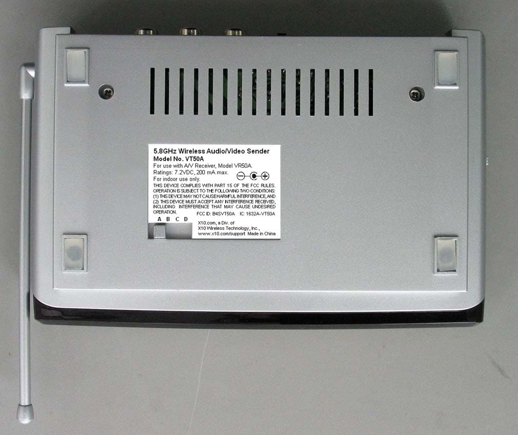
Click to zoom
Application Details
- Equipment Class
- DXX - Part 15 Low Power Communication Device Transmitter
- Date of Grant
- Jan 28, 2008
- Application Purpose
- Original Equipment
- Date of Application
- Jan 28, 2008
- Equipment Note
- WIRELESS AUDIO/VIDEO SENDER
- Frequency Range
- 5758.00000000 - 5810.00000000
- Company
- Authinx Inc.
- Country
- United States
Documents & Files
Document Text
Text extracted from the exhibit documents filed with the FCC. Open a document above to read the original.
Users Manual
M ODEL VK50A W W W W W IRELESS IRELESS IRELESS IRELESS IRELESS A A A A A UDIO UDIO UDIO UDIO UDIO /V /V /V /V /V IDEO IDEO IDEO IDEO IDEO S S S S S ENDER ENDER ENDER ENDER ENDER with dual-source input and IR Extender Feature S ENDER - M ODEL VT50A OWNER’S MANUAL R ECEIVER - M ODEL VR50A 3 2 I NTRODUCTION Your Wireless Audio/Video Sender system consists of a Sender unit whichyou connect to your satellite receiver, DVD player, etc., and a Receiverunit that you connect to a TV located somewhere else in your home. TheAudio/Video Sender converts the audio and video output from your A/Vproduct into a 5.8 GHz wireless Radio Frequency (RF) signal andtransmits it (even through walls) to the Audio/Video Receiver. The Audio/Video Receiver converts the signal back to an A/V signal and passes itthrough a cable to your TV’s Audio/Video input jacks.You can connect two A/V devices to the Audio/Video Sender and youcan select which of these two sources is transmitted to the Audio/VideoReceiver - and you can select this remotely, from the location where theAudio/Video Receiver is located.The Audio/Video Sender system also includes an IR Extender feature.This lets you remotely control the A/V products that are connected to theSender, from the location where the Receiver is located. For example, youcould pause a DVD Player in your living room, or change channels on aSatellite Box in your living room, while watching it on a TV in yourbedroom.There are just a few simple steps to follow to hook up your Audio/VideoSender system to a satellite receiver, VCR, DVD Player, or Cable Box. C ONTENTS I NTRODUCTION ........................................................................ 3 C ONTROLS AND C ONNECTIONS .................................................. 4 S ENDER ............................................................................ 4 R ECEIVER .......................................................................... 5 C ONNECTING U P ..................................................................... 6 H OOKING UP THE S ENDER .................................................... 6 H OOKING UP THE R ECEIVER ................................................. 8 S WITCHING S OURCES BY R EMOTE C ONTROL ............................... 8 IR E XTENDER F EATURE ........................................................... 9 F INE TUNING YOUR S YSTEM .................................................... 10 5 4 RF Antenna(for use with the IRExtender feature) 5.8 GHz Antenna C ONTROLS AND C ONNECTIONS Audio/Video Receiver Audio/Video Sender RF Antenna(for use with the IRExtender feature) Power Supply Jack ON-OFF Switch A/V Out 5.8 GHz ChannelSwitch 5.8 GHz Antenna Power Supply Jack A/V In (Source 1) IR Extender Jack 5.8 GHz ChannelSwitch A/V In (Source 2) A/V Out A/V Out selector switch Source 1 or 2 selector button ON-OFF Switch 7 6 Satellite Box(source 1) Back DVD Player(source 2) Back Hooking up the Audio/Video Receiver1. Using the special cable supplied connect the A/V OUT jack on the Audio/Video Receiver to your TV. 2. Plug the Audio/Video Receiver’s Power Supply into a 120 volt wall outlet and plug its jack into the Audio/Video Receiver. 3. Position the Audio/Video Receiver in a convenient location such as on top of your TV and orient the antenna so that the flat side points in thedirection of the room where you set up the Audio/Video Sender. C ONNECTING U P Hooking up the Audio/Video Sender1. Connect one end of the supplied Audio/Video cable to an A/V device and the other end to the VIDEO and AUDIO jacks of the Audio/VideoSender. Take care to match the colors of the plugs on the cable withthe jacks on the Audio/Video Sender. 2. If desired connect a second A/V device to the Audio/Video Sender using the special cable provided. 3. Using the cable supplied connect the A/V OUT on the Audio/Video Sender to the Audio/Video IN jacks on your TV. See diagram below. 4. Plug the Audio/Video Sender’s Power Supply into a convenient 120 volt wall outlet and plug its jack into the Audio/Video Sender. 5. Position the Audio/Video Sender in a convenient location such as on top of your TV and orient the antenna so that the flat side points in thedirection of the room where you will be installing the Receiver. Selects which of the2 sources is viewedon this TV. Press the button on the back of the Receiver to select the source that’sconnected to the Sender unit (source 1 or source 2) that you want to viewon the TV connected to the Receiver. See next page for how to switchsources by remote control. Source 1 or 2 selector button 9 8 IR emitter Satellite Box(source 1) Front DVD Player(source 2) Front IR emitter Satellite Box(source 1) Back DVD Player(source 2) Back If your second TV is already hooked up to another A/V device:If a Satellite Receiver or other A/V device is already connected to the TVthat you want to connect the Audio/Video Receiver to, you can connect theAudio/Video Receiver to the free LINE IN jacks on the A/V device, usingthe special cable provided. A V COMPONENT V IDEO IN AUDIO IN U SING THE IR E XTENDER FEATURE The IR extender lets you use your remote to control the A/V product thatthe A/V Sender is connected to. E.G., if the Sender is connected to a DVD Player, or Satellite box in your living room, and the Audio/VideoReceiver is connected to a TV in your bedroom; you can control the DVDPlayer or Satellite box while watching the picture from it on the TV in yourbedroom. You do this by pointing your remote control at the Audio/VideoReceiver that’s connected to your bedroom TV. It receives the IRcommands from your remote and converts them to wireless RadioFrequency (RF) commands, and sends them to the Audio/Video Sender . You plug the IR extender cable into the jack on the back of the A/VSender and attach the IR emitters to the front of the DVD Player, or Satellite box, etc., that you want to control. Audio/Video Sender . Model VT50A 1. Plug the IR extender jack on the IR emitter cord into the IR EXT socket located on…
Text truncated - open the document above for the full version.
Cover Letter(s)
January 22, 2008 To: Federal Communications Commission Authorization and Evaluation Division From: Dave Rye Subject: Agent Authorization for certification of FCC ID: B4SVT50A X10 (USA) Inc. hereby appoints Donald Lerner of Retlif Testing Laboratories to act as our agent in the matter of FCC filings for the certification of FCC ID: B4SVT50A. X10 (USA) Inc. further attests that no party to the application is subject to denial of federal benefits pursuant to section 5301 of the Anti-Drug Abuse act of 1988, 21 USA 853(a). Sincerely, Dave Rye Sr. Vice President/Technical Manager X10 (USA) Inc. 620 Naches Ave. SW Renton, WA 98057 (425) 203-3900, e-Fax (208) 730-1506 Web Site: www.x10.com e-mail: [email protected]
ID Label/Location Info
For use with A/V Receiver, Model VR50A. Ratings: 7.2VDC, 200 mA max. For indoor use only. THIS DEVICE COMPLIES WITH PART 15 OF THE FCC RULES. OPERATION IS SUBJECT TO THE FOLLOWING TWO CONDITIONS: (1) THIS DEVICE MAY NOT CAUSE HARMFUL INTERFERENCE, AND (2) THIS DEVICE MUST ACCEPT ANY INTERFERENCE RECEIVED, INCLUDING INTERFERENCE THAT MAY CAUSE UNDESIRED OPERATION. Model No. VT50A rating label 2: 1 9/4/07 5.8GHz Wireless Audio/Video Sender Model No. VT50A FCC ID: B4SVT50A IC: 1632A-VT50A X10.com, a Div. of X10 Wireless Technology, Inc., www.x10.com/support Made in China A B C D
Operational Description
VT50A Operational Description: The VT50A is a composite device that contains a 5.8 GHz FM transmitter and 433 MHz super regenerative receiver. The transmitter operates on one of 4 user selectable channels, A, B, C & D. Their respective frequencies are 5.75 GHz, 5.77 GHz, 5.79 GHz and 5.81 GHz. The VT50A takes the Left, Right and Composite Video Inputs and FM modulates the 5.8 GHz carrier. The signal is then transmitted via a patch antenna to the VR50A, 5.8 GHz receiver, where the process is reversed. The receiver receives a 433 MHz signal from VR50A and sends back an acknowledgement to VR50A.
Parts List/Tune Up Info
0 VT50A(A)=3U VIDEO X'MITTER,433 NOPACK 20070314 1 1 037006=10139 PROTECTIVE FILM,TX20070314 1 1 038010=10040-XLABEL-DATE CODE (WHITE) 20070314 1 1 038010=10513-2 433 MC LABEL20070314 1 1 183010=16396A ANT. COVER, SILVER20070314 1 1 183010=16406 ANT. HOLDER, SILVER20070314 1 1 183010=16422A PLASTIC TUBE, SILVER20070314 1 1 183010=25101 DISK BOTTOM (SILVER) 20070314 1 1 183010=25121 DISK TOP (TX, SILVER)20070314 1 1 183010=25131 HINGE BOTTOM (SILVER) 20070314 1 1 183010=25151 HINGE TOP(TX, SILVER) 20070314 1 1 183010=25161 HINGE HOLDER (SILVER) 20070314 1 1 183010=25171 ON/OFF SWITCH KNOB,SILVER 20070314 1 1 183010=25191 SWITCH COVER (SILVER) 20070314 1 1 183010=25224 LENS,TRANSMITTER20070314 1 1 183010=25370 RUBBER FEET,CLEAR20070314 4 1 185000=26241A TOP CABINET (TX,SILVER) 20070314 1 1 185000=26253 BOTTOM CABINET(TX,SILVER) 20070314 1 1 186002=10490A REAR TRIM LABEL (TX) 20070314 1 1 363=22601000 SINGLE SCREENED20070314 0.22 1 365000=10023 HOT MELT GLUE, HE-38A 20070314 1 1 391=60203060 SCREW-PPTT M2.6X10 MS/ZP 20070314 4 1 391=60203150 SCREW M2.6X8 PA MS/ZP 20070314 2 1 851001=11844 PCB ASSY,5G TX ANT20070816 1 24230 0.2 042010=11955A PCB ANT20070816 1 24227 0.2 363=00000031A COAXIAL RG178B/U 160MM 20070816 1 24227 1 851001=12131 PCB ASSY (433MHZ)20070314 1 0.2 038010=10513-2 433 MC LABEL20040724 1 0.2 042010=11325A PCB20040724 1 0.2 074=60900004 CAP-VAR 6P, SMD20040724 1C16 0.2 076=10200014 CAP-MCC 1N 10% X7R 0603 20040724 2C3,17 0.2 076=10400019 CAP-MCC 100N +8-2 Y5V0603 20040724 2 18893 C19,20 0.2 076=10500016 CAP-MCC 1U +8-2 Y5V 0805 20040724 3C11,13,18 0.2 076=20900012 CAP-MCC 2P .25P NPO 0603 20040724 1C7 0.2 076=27900012 CAP-MCC 2P7 .25P NPO 0603 20040724 1C9 0.2 076=30900012 CAP-MCC 3P .25P NPO 0603 20060724 1 21816 C5 0.2 076=33100023 CAP-MCC 330P 5% NPO 0603 20040724 3C10,12,14 0.2 076=40900012 CAP-MCC 4P .25P NPO 0603 20060724 1 21816 CX1 0.2 076=47000023 CAP-MCC 47P 5% NPO 0603 20040724 1C6 0.2 076=50800012 CAP-MCC 0P5 .25P NPO 0603 20040724 1C4 0.2 076=56100023 CAP-MCC 560P 5% NPO 0603 20040724 1C8 0.2 076=80900012 CAP-MCC 8P .25P NPO 0603 20040724 1C1 0.2 160=10900012 INDUCTOR 1UH 10% SMD 0603 20040724 2L2,4 0.2 162089=10023 COIL 4T5R ID=2 WD=0.420040724 1L1 0.2 209=00000001 TRS-NPN 2N3904 SMD20040724 3Q3,4,5 0.2 209=00000003 TRS-NPN 2SC3356 SMD R25 20060117 1 020866-RCQ1 0.2 209=00000010 TRS-NPN BFS17A SMD20060724 1 21816 Q2 0.2 211103=10027 LDO 5V HT7550-120060807 1 021894-RC 0.2 240=10206011 RES-CF 1K +/-5% 1/8W20040724 1R17 0.2 241=00000003 RES-TFC 0R 5% 1/10W 0603 20040724 1 18847 R19 0.2 241=10000003 RES-TFC 10R 5% 1/10W 0603 20060223 2 021078-RCR7,18 0.2 241=10200003 RES-TFC 1K 5% 1/10W 0603 20040724 2 020866-RCR14,16 0.2 241=10300003 RES-TFC 10K 5% 1/10W 0603 20040724 3 18847 R8,9,12 0.2 241=10500003 RES-TFC 1M 5% 1/10W 0603 20040724 2R10,13 0.2 241=12200003 RES-TFC 1K2 5% 1/10W 0603 20060117 1 020866-RCR4 0.2 241=15200003 RES-TFC 1K5 5% 1/10W 0603 20040724 1R6 0.2 241=22300003 RES-TFC 22K 5% 1/10W 0603 20040724 1R1 0.2 241=39200003 RES-TFC 3K9 5% 1/10W 0603 20040724 1R3 0.2 241=47200003 RES-TFC 4K7 5% 1/10W 0603 20040724 1R2 0.2 241=51200003 RES-TFC 5K1 5% 1/10W 0603 20040724 1R11 0.2 241=56000003 RES-TFC 56R 5% 1/10W 0603 20040724 1R15 0.2 241=91200003 RES-TFC 9K1 5% 1/10W 0603 20040724 1R5 0.2 358=60821001 WIRE-JUMPER D=0.6MM 20040724 4 18893 1 851001=12885 PCB ASSY,MAIN,5G20070314 1 0.2 042010=11863A PCB20070228 1 0.2 057=10000018 CAP-E 10U 20% 25V20070228 1C6 0.2 057=10100019 CAP-E 100U 20% 10V, 5X11 20070228 4C13,106,206,301 0.2 057=10100029 CAP-E 100U 20% 16V 4X7 20070228 1C11 0.2 057=47100010 CAP-E 470U 20% 10V20070228 1C5 0.2 057=47100026 CAP-E 470U 20% 6V3 6.3X11 20070228 3C9,12,302 0.2 076=10400014 CAP-MCC 100N 10% X7R 0603 20070228 6C3,4,6-8,X 0.2 076=15100023 CAP-MCC 150P 5% NPO 0603 20070228 6C102,103,105,202,203,20 0.2 076=15200014 CAP-MCC 1N5 10% X7R 0603 20070228 4C101,104,201,204 0.2 076=22200014 CAP-MCC 2N2 10% X7R 0603 20070228 1C10 0.2 076=22300014 CAP-MCC 22N 10% X7R 0603 20070228 1C2 0.2 149001=10020 3.5MM PCB MT MONO JACK 20070228 1J7 0.2 149=00000005 SOCKET 6 PIN IO CONNECTOR 20070228 2J4,5 0.2 149=00000011 SOCKET RCA PCB-MT(YELLOW)20070228 1J3 0.2 149=00000020 SOCKET RCA PCB-MT (RED) 20070228 1J2 0.2 149=00000021 SOCKET RCA PCB-MT (WHITE) 20070228 1J1 0.2 149=00000022 2.5MM DC JACK20070228 1 0.2 209=00000001 TRS-NPN 2N3904 SMD20070228 4Q1,101,201,301 0.2 209=00000018 TRS-NPN BC817-40 (SOT-23) 20070228 1Q3 0.2 210=00000000 TRS-PNP 2N3906 SMD20070228 4Q2,102,202,302 0.2 211103=10026 LOW DROPOUT REG,1117-3V3 20070228 1REG1 0.2 211328=10248 IC 74HC405320070228 2U1,2 0.2 211328=10324 IC EM78P153S OTP-ROM SMD 20070228 1U3 0.2 212107=10000 DIODE-SI 1N414820070228 2D1,2 0.2 212107=10002 DIODE-SI 1N400420070228 4 024236-RCD4 0.2 220=00200180 LED 3MM (RED DIFFUSED) 20070228 1LED1 0.2 241=00000003 RES-TFC 0R 5% 1/10W 0603 20070228 2R7,8 0.2 241=10200003 RES-TFC 1K 5% 1/10W 0603 20070228 1R1 0.2 241=10300003 RES-TFC 10K 5% 1/10W 0603 20070228 1R3 0.2 241=10400003 RES-TFC 100K 5% 1/10W0603 20070228 2R2,13 0.2 241=12200003 RES-TFC 1K2 5% 1/10W 0603 20070228 1R12 0.2 241=15200003 RES-TFC 1K5 5% 1/10W 0603 20070228 1R4 0.2 241=22200003 RES-TFC 2K2 5% 1/10W 0603 20070228 3R103,203,303 0.2 241=22300003 RES-TFC 22K 5% 1/10W 0603 20070228 1R11 0.2 241=33100003 RES-TFC 330R 5% 1/10W0603 20070228 1R5 0.2 241=47000003 RES-TFC 47R 5% 1/10W 0603 20070228 3R104,204,304 0.2 241=47200003 RES-TFC 4K7 5% 1/10W 0603 20070228 6R102,106,202,206,302,30 0.2 241=47300003 RES-TFC 47K 5% 1/10W 0603 20070228 1R10 0.2 241=56300003 RES-TFC 56K 5% 1/10W 0603 20070228 2R8,9 0.2 241=68000003 RES-TFC 68R 5% 1/10W 0603 20070228 5R6,105,205,305,307 0.2 241=82000003 RES-TFC 82R 5% 1/10W 0603 20070228 2R101,201 0.2 283=00000003 SLIDE-SW SS12F21 (1P2T) 20070228 2SW1,2 0.2 283=00000049 SLIDE SW 1P4T (SK-14D01) 20070228 1SW3 0.2 358=60821001 WIRE-JUMPER D=0.6MM 20070228 23 1 851001=12902 PCB ASSY 5.8G TX MODULE 20070314 1 0.2 042010=11846A PCB20070314 1 0.2 076=10000022 CAP-MCC 10P .25P C…
Text truncated - open the document above for the full version.
Schematics
1 2 3 4 5 6 ABCD 6 5 4 3 2 1 D CBA Title Number Revision Size B Date: 4-Sep-2007 Sheet of File: C:\5GVT.SCH Drawn By: X0 12 X1 13 Y0 2 Y1 1 Z0 5 Z1 3 INH 6 A 11 B 10 C 9 VEE 7 X 14 Y 15 Z 4 VCC 16 GND 8 U1 4053 X0 12 X1 13 Y0 2 Y1 1 Z0 5 Z1 3 INH 6 A 11 B 10 C 9 VEE 7 X 14 Y 15 Z 4 VCC 16 GND 8 U2 4053 J3 YELLOW J2 RED J1 WHITE VIDEO AUDIO R AUDIO L TO 5.8G Module VDD 4 VSS 11 P62 8 P64 6 P65 5 P53 12 P52 13 P51 14 P50 1 P67 2 P66 3 P61 9 P60 10 P63 7 U3EM78P153E +5V +5V SW1 Ch.SW C8100nF C7 100nF Q101 3904 R102 4K7 R105 68R +5V Vin 1 GND 3 +5V 2 REG1H1117 C1100uF/25V C4 100uF/10V SW1SW-SLIDE +3V3 J4DC JACK C11100nF R1032K2 R104 47R +3V3 IN GND +3V3 +6V +5V Q2013904 R2024K7 R205 68R R2032K2 R204 47R +5V 123456 J5 Mini Din R1 1K Q1BC817 R2100K R310K D3 4148 C2 22N Q2 3906 R70R J7 PHONEJACK C610u R41K5 R5330R R668R +5V 25V D4 4148 R856K +6V 310/433.92MHz RF Receiver Daughter Board C5100u 10V 123456 J6 Mini Din 56K R9 C102N2 47K R423 Q403 R422 3904 22K C106 100uF/10V C206 100uF/10V C204 1N5 C205150P C201 1N5 C202150P C1011N5 C102150P C1041N5 C105 150P +5v Q301 3904 R302 4K7 R305 68R +5V R303 2K2 R304 47R C301 100u C302470u +5V C9 470UF/6.3V R13100K R12 1K2 LED1 RED R201 82R R10182R Q102 3906 Q202 3906 R106 4K7 R206 4K7 SMD SMD SMD SMD SMD SMD SMD SMD SMD SMD SMD SMD SMD SMD SMD SMD SMD SMD SMD SMD SMD C203 150pF C103 150pF 6V3 +5V D14001 C12 100u 10V OUT IN R307 75R Q2023906SMD R3064K7 SMD SMDSMD SMD SMD SMD SMD SMD SMD SMD SMD SMD SMD SMD SMD SMD SMD SMD SMDSMD SMD SMD SMD SMD SMD SMD SMD SMD SMD SMD +6V R1070RR1080R R1090R R2070R R2080RR2090R C107100U C207100U Mini Din Connection :Pin 1 : White - Left Audio - 6M ( Z )Pin 2 : Yellow - Video ( Y )Pin 3 : GndPin 4 : N/CPin 5 : GndPin 6 : Red - Right - 6M5 ( X ) CX1N SMD CY1N SMD CZ100N SMD 11 22 33 44 D D C C B B A A 1 SYSTEM X-10 H.K. LTD.Created: Kam @20060425Updated By: Kam 1 AV TRANSMITTER '=11677 -5 20070123F:\10WORK\2G4\RW67 series-XT\67 Tx\=11677-5.SCHDOC TitleSize: No: Date:File: Revision:Sheet of A4 Cannot open file E:\Documents and Settings\chengchia\My 9/5/2007 10KR20 470nF C21 100nF C24 33pFC23 8MHz 080-00000048 Y1 33pFC22 SPI_SE 10KR30 10K R33 10K R34 10K R35 CH0CH1CH2 D_3.3V 4.7uFC25 3.3V 560pC32 20K R11 680R7 20KR12 750R28 10uF C36 Audio Right IN 51K R18 1uFC15 2.2uFC17 100K R31 1uFC39 3.3V VT 20KR9 750R27 10uF C35 51K R17 1uFC14 100K R32 560pC31 20K R8 680R26 2.2uFC16 1uFC12 1.2K R14 75RR13 4.7uFC19 **C6 10KR19 75RR16 20KR10 0RR5 1.2KR15 ** C4 47pF C9 680pF C10 82pC11 820pF C5 820nH 0603 L5 820nH 0603 L4 VT Video_In 100KR22 15nFC20 110RR21 1uFC13 4.7uF C18 3.3V 3.3V 2.7nH L3 4.7nH L2 1pFC2 10pFC1 39R2 8.2nHL1 10pFC3 3.3V AUDIO LEFT IN VCOVDD 1 VT 2 GND 3 CP 4 AVT2 5 ACP2 6 AOUT2 7 AVDD2 8 AOUT1 9 NC 10 AVT1 11 ACP1 12 AVDD1 13 VDD 14 SPI_SE 15 BCR 16 REG1D8 17 PD_REG1D8 18 XTAL1 19 XTAL2 20 VDD33 21 SPICLK/CS0 22 SPILE/CS1 23 SPIDATA/CS2 24 BX 25 SYNVSS 26 RFGND2 27 PAOUT2 28 PAOUT1 29 RFGND1 30 PAVDD 31 NC 32 RTC6701A 211328=10382 U1 100nC103 0R L6 +V D_3.3V 3.3V 100nC102 NP 10nF C101 IN 1 GND 2 EN 3 BP 4 OUT 5 VIDEO_INARAL 123456 CON7P1 RFOUT 47nFC96 47n C97 47nFC98 1234567 CON7P2 BX CH0CH1CH2 +V 10pFC26 10pFC810pFC7 BX RFOUT **R1 6M 6M5 WHITE RED 10K R36 C34 18pF C51 18pFC53 +5V NP C27 1 3 2 110-00000015 F1 11677B -B Date By Detail KAM 20060914 Ass'y: 851001=12575 / 12742 /12843/12963 2G4 TX A 011B 101C 110D 111 US/EUR2414M2432M2450M2468M Ch CS0-2 AUS 2414M2432M2450M 5p6C40 5p6C41 82KR52 82KR50 0RR34 100nC100 851001=12742 ASY 2G4 TX - WB851001=12575 ASY G4 TX - RT C4 C5 C6 C9 C10 27p 820p 820p 47p 680p open 820p 220p 47p 680p ** Remark: 0p75C02 0p75C01 0p75 C0 1n5H L0 851001=12843 ASY G4 TX - RT F1 C0 2012 2012 0p75 L0 1n5H R100 5R6 0p751n5H 0 851001=12963 ASY G4 TX - RT OPEN for 5G Tx =1180x-9-FCC.sch-1 - Wed Sep 05 10:54:43 2007 1 2 3 4 5 6 78 ABCD 8 7 6 5 4 3 2 1 D CBA Title Number Revision Size A3 Date: 24-Apr-2007 Sheet of File: C:\TEMP\VTRX1.SCH Drawn By: C1 8P C3 1N C4 0P5 C17 1N CX1 4P C12330PC13 1U ANT L1 4T5R L21U R1 22K R5 9K1 R7 10R R18 10R R2 4K7 Q1 2SC3356 L3 PCB C16 6P C5 3P C15 * C6 47P Q2 BFS17A R3 3K9 R19 0R R4 1K2 +5V R6 1K5 L41U C8 560P VI G VO U1 HT7550-1 C9 2P7 R8 10K R9 10K R10 1M R11 5K1 R12 10K R13 1M R14 1K R15 56R R17 1K R16 1K C10 330P C11 1U Q3 3904 Q4 3904 Q5 3904 +5V VIN C14 330P RFO C7 2P VAR C19 * C20 100N 03 +5V RFO +VIN GND PCB : 042010=11325A ASSY NO.: 851001=12131 C18 1U 1/8W RF RECEIVER (433.92MHz) NOTE : ALL UNSPECIFIED RESISTORS OR CAPACITORS ARE USE 0603 TYPE SMD TRACE
Test Report
Retlif Testing Laboratories,TransmitterTest ReportR-12106-1,X10 (USA), Inc., FCC ID: B4SVT50A Page1of36 Technical Information APPLICANTMANUFACTURER Name:X10 (USA), Inc.Name:X-10 Electronics (Shenzhen) Co. Ltd. Address: Blackriver Corporate Park 620 Naches Ave SW, Building AAddress: Together Rich Industrial Park B Sanwei Industrial District, XixiangTown City, State, Zip:Renton, WA 98057City, State, Zip: Baoan County, Shenzhen, China TEST SPECIFICATION: FCC Rules and RegulationsPart 15, Subpart C, Section 15.249 TEST PROCEDURE:ANSI C63.4:2003 Test Sample Description Test Sample:5.8GHz Wireless Audio/Video Sender Brandname(s):X10 (USA) Model(s):VT50A FCC ID:B4SVT50A Type:Frequency ModulatedTransceiver Power Requirements:6 VDC, 300 mA derived from external AC Adapter Frequency Of Operation:5.75 GHzto 5.81 GHz Applicable Rule Section:Part 15, Subpart C, Section 15.249 Tests Performed Transmitter: -15.207(a)Conducted Emissions -15.249(a)Occupied Bandwidth -15.249(c)/15.209Radiated Emissions, Spurious Case -15.249(a)Radiated Emissions, Fundamental and Harmonics Retlif Testing Laboratories,TransmitterTest ReportR-12106-1,X10 (USA), Inc., FCC ID: B4SVT50A Page2of36 Test Results Transmitter: 15.203:The intentional radiator is designed to ensure that no antenna other than that furnished by the applicant can be used with the device. 15.207(a):The radio frequency voltage that was conducted back on to the AC power line on any frequency/frequencies within the bandwidth of 150 kHz to 30 MHz did not exceed Class B limits as specified in CISPR 22. 15.249 (a):The unit operates in5725 GHzto5875 GHzband. The field strength of the fundamental did not exceed50mV/Maverage. The field strength of the harmonics did not exceed500μV/Maverages. 15.249 (b):Field strength readings were taken at 3 meters unless otherwise noted. 15.249 (c):Emissions radiated outside the specified frequency band were attenuated in accordance with the general radiated emissions limits of 5.209. 15.249 (d):The peak field strength of any emission did not exceed the maximum permitted average field strength bymore than 20 dB. Retlif Testing Laboratories,TransmitterTest ReportR-12106-1,X10 (USA), Inc., FCC ID: B4SVT50A Page3of36 Spectrum Analyzer Desensitization Considerations General Notes 1.The AC input was varied from 85% to 115% of the rated input. Field strength measurements were taken with the AC input adjusted to produce maximum emissions. 2.Alluser accessible controls were adjusted to produce maximum emissions. 3.The device was tested with the following external accessories: -AC switching power supply Model Number: S002CU0720020. -IR extender Cable-4.0 meters long. -Audio/Video Cable-1.5 meters long. -2 S-Video Cables-1.5 meters long. -Panasonic VCR Model Number: PV-V4020. 4.Measurements of Conducted Emissions were performed utilizing a 50 ohm / 50 μhenry Line Impedance Stabilization Network (LISN). 5.The frequency range was scanned from 30 MHz to 40 GHz. All emissions not reported were more than 20 dB over the specified limit. Channel AChannel BChannel CChannel D 7.The unit operates at the following frequencies: 5.75 GHz5.77 GHz5.79 GHz5.81 GHz Theunit was tested at the following frequencies: 5.75 GHz-5.79 GHz5.81 GHz Retlif Testing Laboratories,TransmitterTest ReportR-12106-1,X10 (USA), Inc., FCC ID: B4SVT50A Page5of36 Equipment List Transmitter FCC Part 15, Subpart C,Conducted Emissions, 150 kHz to 30 MHz ENTypeManufacturerDescriptionModel No.Cal DateDue 078LISNSolar Electronics10 kHz-30 MHz8028-50-TS24BNC7/5/20077/5/2008 079LISNSolar Electronics10 kHz-30 MHz8028-50-TS24BNC7/5/20077/5/2008 333AttenuatorNardaDC-11 GHz768-108/10/20078/10/2008 456LISNSolar ElectronicsDC-60 Hz9409-50-R-2412/4/200612/4/2007 7016EMC AnalyzerHewlett Packard9 kHz-1.8GHz8591EM7/25/20077/25/2008 762AM/FM Signal GeneratorMarconi Instru.10 kHz-1.2 GHz20237/24/20077/24/2008 FCC Part 15, Subpart C, Occupied Bandwidth ENTypeManufacturerDescriptionModel No.Cal DateDue Date 067Open Area Test SiteRetlif3/10 MeterRNY9/12/20069/12/2009 128Double Ridged GuideElectro-Mechanics1 GHz-18 GHz31053/27/20073/27/2008 141Spectrum AnalyzerHewlett Packard100 Hz-40 GHz8566B4/27/20074/27/2008 141BQuasi-Peak AdaptorHewlett Packard100 Hz-1 GHz85650A4/27/20074/27/2008 512Graphics PlotterHewlett PackardN/A7470A10/19/200710/19/2008 723H.P. FilterMini-Circuits1 GHzBHP-10008/13/20078/13/2008 FCC Part 15, Subpart C, Spurious Case Radiated Emissions ENTypeManufacturerDescriptionModel No.Cal DateDue Date 066High Gain Horn AntennaMicrolab/FXR8.2 GHz-12.4 GHzX638A8/30/20078/30/2008 067Open Area Test SiteRetlif3/10 MeterRNY9/12/20069/12/2009 128Double Ridged GuideElectro-Mechanics1 GHz-18 GHz31053/27/20073/27/2008 129DHigh Gain Horn AntennaMicrolab/FXR12.4 GHz-18 GHzY638A8/30/20078/30/2008 129FHigh Gain Horn AntennaMicrolab/FXR18 GHz-26.5 GHzK638A8/30/20078/30/2008 129GHigh Gain Horn AntennaMicrolab/FXR26.5 GHz-40 GHzU638A8/30/20078/30/2008 141Spectrum AnalyzerHewlett Packard100 Hz-40 GHz8566B4/27/20074/27/2008 141BQuasi-Peak AdaptorHewlett Packard100 Hz-1 GHz85650A4/27/20074/27/2008 420AmplifierHewlett Packard2.0 GHz-18 GHz11975A11/14/200612/12/2007 421Harmonic MixerHewlett Packard18 GHz-26.5 GHz11970K10/3/200610/3/2009 421AHarmonic MixerHewlett Packard26.5 GHz-40 GHz11970A10/3/200610/3/2009 512Graphics PlotterHewlett PackardN/A7470A10/19/200710/19/2008 523BiconilogElectro-Mechanics26-2000 MHz3142B10/24/200710/24/2008 543PreamplifierHewlett Packard1.0 GHz-26.5 GHz8449B9/26/20079/26/2008 617Interference AnalyzerElectro-Metrics10 kHz-1 GHzEMC-3010/24/200710/24/2008 723H.P. FilterMini-Circuits1 GHzBHP-10008/13/20078/13/2008 Retlif Testing Laboratories,TransmitterTest ReportR-12106-1,X10 (USA), Inc., FCC ID: B4SVT50A Page6of36 FCC Part 15, Subpart C, Radiated Emissions, Fundamental and Harmonics ENTypeManufacturerDescriptionModel No.Cal DateDue Date 066High Gain Horn AntennaMicrolab/FXR8.2 GHz-12.4 GHzX638A8/30/20078/30/2008 067Open Area Test SiteRetlif3/10 MeterRNY9/12/20069/12/2009 128Double Ridge…
Text truncated - open the document above for the full version.
Test Setup Photos
Retlif Testing Laboratories, Test Report R-12106-1, X-10(USA), FCC ID: B4SVT50A Page 1 of 5 Transmitter, Conducted Emissions, Right Side Setup View Transmitter, Conducted Emissions, Front Side Setup View Retlif Testing Laboratories, Test Report R-12106-1, X-10(USA), FCC ID: B4SVT50A Page 2 of 5 Transmitter, Conducted Emissions, Left Side Setup View Receiver, Conducted Emissions, Front Side Setup View Retlif Testing Laboratories, Test Report R-12106-1, X-10(USA), FCC ID: B4SVT50A Page 3 of 5 Transmitter, Occupied Bandwidth, Test Setup Transmitter, Radiated Emissions, Spurious Case, Rear View Setup Retlif Testing Laboratories, Test Report R-12106-1, X-10(USA), FCC ID: B4SVT50A Page 4 of 5 Transmitter, Radiated Emissions, Spurious Case, Front View Setup Transmitter, Radiated Emissions, Fundamental and Harmonics, X-Axis Setup Retlif Testing Laboratories, Test Report R-12106-1, X-10(USA), FCC ID: B4SVT50A Page 5 of 5 Transmitter, Radiated Emissions, Fundamental and Harmonics, Y-Axis Setup Transmitter, Radiated Emissions, Fundamental and Harmonics, Z-Axis Setup
Contact Information
Applicant
Shane Houshmand(Chief Operating Officer)
Test Firm
Retlif Testing LaboratoriesScott Wentworth
Technical Specifications
| # | Rule Parts | Frequency Range | Power Output |
|---|---|---|---|
| 1 | 15C | 5.76 GHz - 5.81 GHz | - |
Other Applications from Authinx Inc.

B4SXC35A
Jun 16, 2011Wireless Color Camera
Equipment Class
DXX - Part 15 Low Power Communication Device Transmitter
B4SVT50
Jun 16, 2011Wireless Audio/Video System
Equipment Class
DXX - Part 15 Low Power Communication Device Transmitter
B4SVR50
Jun 13, 2011Wireless Audio/Video Receiver
Equipment Class
DSC - Part 15 Security/Remote Control Transmitter
B4S-XC30A
Jun 07, 2011Wireless Color Camera
Equipment Class
DXX - Part 15 Low Power Communication Device Transmitter
B4SIR34A
Aug 01, 2010Remote Control Transmitter
Equipment Class
DSC - Part 15 Security/Remote Control Transmitter