B5DM536Single Receiver UHF Wireless Intercom Beltpack
Bosch Security Systems, Inc.
Click to zoom
Application Details
- Equipment Class
- TLD - Licensed LPAS Device
- Date of Grant
- Mar 18, 2020
- Application Purpose
- Original Equipment
- Date of Application
- Mar 18, 2020
- Equipment Note
- Single Receiver UHF Wireless Intercom Beltpack
- Frequency Range
- 590.10000000 - 607.90000000
- Company
- Bosch Security Systems, Inc.
- Country
- United States
Documents & Files
Document Text
Text extracted from the exhibit documents filed with the FCC. Open a document above to read the original.
Users Manual
F.01U.187.426 Rev. 19 JUNE / 2019 BTR-800, TR-800, TR-825 Professional Wireless Intercom System Operating Instructions 2 BTR-800, TR-800, TR-825 Table of Contents INTRODUCTION .............................................7 General Description ..............................................7 System Features ....................................................7 BTR-800 BASE STATION ...............................9 Controls and Connections – Front Panel ...................9 BTR-800 Specifications ..........................................11 TR-800 BELTPACK .......................................13 Controls and Connections – Top Panel ...................13 TR-800 Specifications .............................................15 TR-825 BELTPACK .......................................17 Controls and Connections – Top Panel ...................17 TR-825 Specifications .............................................19 INITIAL EQUIPMENT SETUP ....................21 Unpacking ...............................................................21 Antenna Connection ................................................22 Antenna Polarization ...............................................22 Distance between Antennas ....................................22 Antenna Placement ..................................................22 Improving Reception and Increasing Range ...........24 Base Station Set-up .................................................25 Location ...................................................................25 Power Connection ...................................................25 Transmit Switches ...................................................25 Internal Transmit Switches ......................................26 Intercom Switch ......................................................26 Intercom Interface ...................................................26 Dual Listen Functionality ........................................28 Auxiliary Input/Output ............................................29 Internal Auxiliary Input Routing Switch .................29 Stage Announce / Relay Contacts ...........................30 Base Station Link ....................................................31 Beltpack Setup .........................................................32 Antenna Connection ................................................33 Transmit Mode ........................................................33 Headset Connection .................................................33 PRE-WALK-THRU CHECKLIST .................35 SYSTEM OPERATION ..................................37 Frequency Plan Overview .......................................37 Factory-Defined Groups ..........................................37 User-Programmable Groups ....................................37 System Quick Start ..................................................37 Base Station Operation ............................................38 Power .......................................................................38 Local Headset ..........................................................38 Portable Station Connect .........................................38 Intercom A and B ....................................................38 Auxiliary ..................................................................38 Display Contrast ......................................................39 BTR-800 Menu Structure ....................................40 Main Screen Flowchart ............................................40 Power-Up Screen .....................................................41 Operating Screen .....................................................41 Beltpack Activity Code Definitions ........................42 Group/Channel Select ..............................................43 Group/Frequency Select ..........................................44 Frequency Edit (User-Programmed Groups Only) ...........................45 ClearScan™ .............................................................46 Special Key Sequences ............................................47 Lockout ....................................................................47 Copy .........................................................................47 1st Use Default ........................................................47 Factory Default ........................................................47 Beltpack Operation ..................................................48 On/Off and Volume Control ....................................48 Battery Check ..........................................................48 Talk Button ..............................................................48 Microphone Gain .....................................................48 Audio Channel Select Button ..................................48 Stage Announce (SA) ..............................................48 Wireless Talk Around (WTA) .................................48 TR-800 Menu Structure ......................................49 Beltpack Menu Structure .........................................49 Power-Up Screens ...................................................50 Group/Channel Screen .............................................51 Transmit Screen .......................................................52 Receive 1 Screen .....................................................53 Receive 2 Screen .....................................................54 ClearScan™ .............................................................55 Stage Announce Enable/Disable .............................56 Wireless Talk Around Enable/Disable ....................56 Audio Channel A or B Disable/Enable ....................57 Talk Button Latch on/Latch off ...............................57 Special Key Sequences ............................................58 Lockout ....................................................................58 1st Use Default ........................................................58 …
Text truncated - open the document above for the full version.
Users Manual
48 System OperationBTR-800, TR-800, TR-825 Beltpack Operation FIGURE 37. TR-800 and TR-825 Top and Rear Panel On/Off and Volume Control Turn the beltpack power on by rotating the knob CW. Adjust the volume to the headset by rotating the volume control as required for a comfortable listening volume. Battery Check When the beltpack power is turned on by rotating the knob, the BAT/OM LED will flash once if the battery is good. If the LED stays on, the battery is low. If the LED does not flash, the battery is dead. Talk Button Press the talk button to enable the audio path from the headset microphone. The TALK/OM LED will turn red when audio is enabled. A quick press and release latches the talk function unless latching has been disabled. Holding the button for over 1/ 2 a second will cause the audio path to be enabled only for as long as the button is held. If the talk function is latched on, pressing the talk button again will turn it off. See “Talk Button Latch on/Latch off” on page 57 to learn how to enable/disable latching of the talk button. Microphone Gain Adjusts the headset’s microphone gain. Adjust so the TALK/ OM LED flashes red at the beginning of most words at normal speech levels. If the input is too large, the LED will be red during the complete word at normal speech level. The peak- responding audio limiter in the beltpack is very tolerant of high input audio levels. Even when the microphone gain is maximized, and headset volume reduced to make up for the louder audio, the audio will still sound good and not clipped. Audio Channel Select Button Selects the intercom system to which the headset is connected. The LED near the channel button indicates the current selection. See the “Audio Channel A or B Disable/Enable” on page 57 to learn how to enable only channel A, channel B, or both. Stage Announce (SA) When pressed the audio from the beltpack is routed directly to the stage announce connector on the back of the base station. The base station’s SA relay is also closed. The beltpack sidetone is lost as an indication that stage announce is activated. The other beltpacks and wired users do not hear this beltpacks audio when SA is pressed. The button is non-latching and activates the nearby red LED when pressed. See “Stage Announce Enable/ Disable” on page 56 to learn how to enable/disable the SA button. Wireless Talk Around (WTA) When pressed, the audio from the beltpack is disconnected from the wired intercom, auxiliary input/output and the base station’s local headset. Other beltpack users, on that audio channel, can hear the user as normal. The button activates the nearby red LED as well as the appropriate talk LED when pressed. See the “Wireless Talk Around Enable/Disable” on page 56 to learn how to enable/disable the WTA button as well as other features. BTR-800, TR-800, TR-825System Operation 49 TR-800 Menu Structure Beltpack Menu Structure The following contains the main beltpack menu structure and references the pages in which further detail of that menu may be found. All beltpack features and special key sequences can only be done from the group/channel screen. Beltpack Feature Enable/Disable Menus Stage Announce (SA) Enable/Disable .................page 56 Wireless Talk Around (WTA) Enable/Disable .....page 56 Audio Channel A/B Enable/Disable....................page 57 Talk Button Latching/Non-Latching....................page 57 Other Special Key Sequences Lockout ..............................................................page 58 1st Use Default ..................................................page 58 Factory Default .................................................page 58 NOTE:Pressing [MENU] within a screen after action has occurred escapes from that action and places the user at the current screen. Any editing that had been done since [SET] had been pressed is aborted. FIGURE 38. Power-Up Screen 50 System OperationBTR-800, TR-800, TR-825 Power-Up Screens •The first screens displayed when the beltpack is powered up are the software and channel map version screens. •The 1st screen displayed indicates the beltpack’s software version number. It is displayed for about one second. •The 2nd screen displayed indicates the beltpack’s channel map (frequency plan) version number. It is displayed for about one second. •The final screen displayed is the group/channel screen. BTR-800, TR-800, TR-825System Operation 51 Group/Channel Screen The Group/Channel screen allows the user to change the group and select from a pre-determined number of transmit channels. •The screen displayed after the beltpack power-up screens. •Press [SET] to edit the channel number. The channel number will start flashing. •Use the [UP]/[DOWN] arrow buttons to change the channel number •Press [SET] to place the beltpack on the channel selected. Once set is pressed, the beltpack transmitter will move to that frequency and nothing will be flashing. Now press [SET] twice to enter group edit. •Use the [UP]/[DOWN] arrow buttons to change the group number. •Press [SET] to place the beltpack on the group selected. Once set is pressed, the unit returns to the group/channel display with nothing flashing. •Pressing [SET] once more will start the editing sequence over again. Pressing [MENU] during the group edit will end editing and send the user back at the group/channel screen without any changes. This applies to channel editing too. 52 System OperationBTR-800, TR-800, TR-825 Transmit Screen The Transmit screen allows the user to set the beltpack transmit frequency. Factory-defined groups will allow only a set number of pre-defined frequencies to be selected. User-programmable groups will allow the user to change the frequency in 25kHz steps. •Press [MENU] once from the group/channel screen to arrive at the transmit frequency screen. •Press [SET] to edit the frequency. The number will start flashing. •Use the [UP]/[DOWN] arrow buttons to change the frequency. •Press [SET] to place the beltpack on the frequency …
Text truncated - open the document above for the full version.
Users Manual
APPLICATIONS CHG. NO. LTR REVISIONS DESCRIPTIONDATE APPD DATE DR BY CHK BY APPD. PROD. TOLERANCES UNLESS OTHERWISE SPECIFIED FRACTION DECIMAL ANGLE This drawing, written description or specifi- cation represents a proprietary product of Telex, Lincoln, NE, and shall not be released, disclosed, used nor duplicated without the written permission of TELEX SIZE CODE IDENT DWG. NO. S TELEX TELEX COMMUNICATIONS, INC. Lincoln, Nebraska U.S.A. TITLE UNLESS OTHERWISE SPECIFIED DIMENSIONS ARE IN INCHES. 57010 F01U187426 SCALE: NONE SHEET: 1 of 1 JRC 09-23-10 MSD F01U187426 8 1/2” BTR-800, TR-800, TR-825 INSTRUCTION MANUAL 11” F 12-54-03 Add CE information 01-05-04 JA Eliminate Customer Service & Limited Warranty Eliminate Customer Service & Limited Warranty in T.O.C. 03-49-04 04-22-04 DO G H Update manual for European requirements 03-16-05 JRC 70-000340 J Add CE info. for TR-825, add new band info. 10-04-07 JRA 70-001043 0891 K 01-13-09 JRC 70-001335 Correct anntenna chart -update chrg. Part # JRC 09-23-10 70-001575 L Update base antennas. 02-22-10 JRC 70-001661 M Add FCC notice; CE info; Canada info. 02-22-10 JRC N 70-001723 Add turn off warning before replacing bat pack for TR-825. 07-12-10 JRC P 70-001759 Add current warning and clearscan setup 06-10-10 JRC 16 F03X046765 Remove certified body, alert symbol and DoC. Add website reference for full DoC 06-07-17 MMB 17 F03X050743 Add additional battery warnings for TRs, clean up TELEX and Radiocom with RTS 03-01-18 MMB 18 F03X054287 Add language for the new U band frequencies for U.S. 06-06-18 MMB 19 NEXT ASSY. USED ON Add new bands information 06-25-19 MMB F03X063256
Cover Letter(s)
February 27, 2020 Subject: Declaration of electrical identical models for New Family Certification for IC: 1321A-TR800DE Under this IC number are three models of wireless intercom beltpacks: TR-800-FD, TR-800-FE and TR-800-HE. We, Bosch Security Systems, Inc., declare these models are identical in function, mechanical layout and electrical components. The only difference in the models are restrictions of their overall allowed t ransmit and receive ranges under IC: 1321A-TR800DE. The frequency bands of th e three models are defined below: TR-800-FD RX: 482 – 500 MHz TX: 572 – 590 MHz TR-800-FE RX: 482 – 500 MHz TX: 590 – 608 MHz TR-800-HE RX: 500 – 518 MHz TX: 590 – 608 MHz. All other aspects of these three models are identical. S incerely, J ames Andersen / Principal Electrical Engineer Bosch Security Systems, Inc.
Cover Letter(s)
SCS-F18: Project and Product Certification Representative Authorization Letter Page 1 of 1 Rev 6.0 February 19, 2020 To: BVCPS, INC. 775 Montague Expressway, Milpitas, CA 95035 USA Dear Sir/Madam, Re: Project and Product Certification Representative Authorization Letter We, Bosch Security Systems, Inc., hereby authorize Bureau Veritas Consumer Product Services, Inc. to act as a Certification Body for certifying for the following project(s): FCC ID: B5DM536 Product Description: Wireless Intercom Beltpack Model: TR-800 We affirm that between Bureau Veritas Consumer Product Services, Inc. and Bosch Security Systems, Inc., any difference in understanding, including test plan, measurement methods, applicable standards and relevant procedures and processes have been resolved prior to commencement of testing activities. Sincerely, James Andersen / Principal Electrical Engineer Bosch Security Systems, Inc
Cover Letter(s)
February 19, 2020 To: Federal Communications Commission Authorization and Evaluation Division 7435 Oakland Mills Road Columbia, MD Subject: Permanent Confidentiality Request for FCC ID: B5DM536 Pursuant to sections 0.457 and 0.459 of CFR 47, we respectfully request permanent confidential treatment of the following Exhibits accompanying this application as: - e.g. Block Diagram - e.g. Schematics - e.g. Operational Description The above materials contain trade secrets and proprietary information not customarily released to the public. The public disclosure of these materials may be harmful to the applicant and provide unjustified benefits to its competitors. The applicant understands that disclosure of this application and all accompanying documentation will not be made before the date of the Grant for this application. Sincerely, James Andersen / Principal Electrical Engineer Bosch Security Systems, Inc
Cover Letter(s)
February 19, 2020 To: Federal Communications Commission Office of Engineering and Technology Equipment Authorization Division 7345 Oakland Mills Road Columbia, Maryland 21046 Subject: Short Term Confidentiality Request for FCC ID: B5DM536 To Whom It May Concern: Pursuant to sections 0.457 and 0.459 of CFR 47, and to avoid premature release of sensitive information prior to marketing or release of the product to the public, the applicant requests the following documents contained in this certification application be temporarily withheld from public disclosure for an initial period of 45 or 180 days; or for a specified date of / / not to exceed 180 days from the Grant Date. See KDB 726920. - e.g. User Manual - e.g. Internal Photos - e.g. Test Setup photos - e.g. External Photos The above materials contain trade secrets and proprietary information not customarily released to the public. The public disclosure of these materials may be harmful to the applicant and provide unjustified benefits to its competitors. Sincerely, James Andersen / Principal Electrical Engineer Bosch Security Systems, Inc
External Photos
EUT Photo-External view EUT – Front View EUT – Rear View EUT – Top View EUT – Bottom View EUT – Left View EUT – Right View
ID Label/Location Info
RoHS STANDARD ENVIRONMENT REQUIREMENT : NO BANNED SUBSTANCES ACC. TO N2580-1 Design of the label has to follow the latest Corporate Design ST Product and Packaging Labels F01U375146 Label Size 38.00 X 12.50 Freimaßtol. / TOLERANCES Fehl. Angaben / MISS. DETAILS Dokumentenart / DOCUMENT TYPE DRW Stueckliste besonderes Blatt / PARTS LIST ON SPECIAL SHEET Oberfläche SURFACE Datum/DATE gep.CHK. Original: Nr NO Aenderung CHANGE gueltig VALID Ers.d. / REPLACED BY de/en Blatt SHEET 1 Bemerkung / TITLE Stoff / MATERIAL aus / FROM Massstab SCALE Gewicht WEIGHT DIN A4 Gr.St. VOLUME Nr. / NO. Name/NAME gez./DWN. ges/APP Ers. f. / REPLACES 1 BL/SH gez. DWN. Spezial Label TSS - F01U375146 Security Systems 5/31/2019RAJ1BUV 5/31/2019RAJ1BUVF03X0622930101
ID Label/Location Info
TR-800 Labels are located under battery pack. Product label FCC ID and part 15 label
ID Label/Location Info
RoHS STANDARD ENVIRONMENT REQUIREMENT : NO BANNED SUBSTANCES ACC. TO N2580-1 Design of the label has to follow the latest Corporate Design ST Product and Packaging Labels F01U359398 Label Size 26.00 X 12.50 mm Freimaßtol. / TOLERANCES Fehl. Angaben / MISS. DETAILS Dokumentenart / DOCUMENT TYPE DRW Stueckliste besonderes Blatt / PARTS LIST ON SPECIAL SHEET Oberfläche SURFACE Datum/DATE gep.CHK. Original: Nr NO Aenderung CHANGE gueltig VALID Ers.d. / REPLACED BY de/en Blatt SHEET 1 Bemerkung / TITLE Stoff / MATERIAL aus / FROM Massstab SCALE Gewicht WEIGHT DIN A4 Gr.St. VOLUME Nr. / NO. Name/NAME gez./DWN. ges/APP Ers. f. / REPLACES 1 BL/SH gez. DWN. Product Label TR-800-FD TSS - F01U359398 Security Systems 6/11/2019RAJ1BUV 6/11/2019RAJ1BUVF03X0623470101 Label Size 38.00 X 12.50
ID Label/Location Info
RoHS STANDARD ENVIRONMENT REQUIREMENT : NO BANNED SUBSTANCES ACC. TO N2580-1 Design of the label has to follow the latest Corporate Design ST Product and Packaging Labels F01U359407 Label Size 26.00 X 12.50 mm Freimaßtol. / TOLERANCES Fehl. Angaben / MISS. DETAILS Dokumentenart / DOCUMENT TYPE DRW Stueckliste besonderes Blatt / PARTS LIST ON SPECIAL SHEET Oberfläche SURFACE Datum/DATE gep.CHK. Original: Nr NO Aenderung CHANGE gueltig VALID Ers.d. / REPLACED BY de/en Blatt SHEET 1 Bemerkung / TITLE Stoff / MATERIAL aus / FROM Massstab SCALE Gewicht WEIGHT DIN A4 Gr.St. VOLUME Nr. / NO. Name/NAME gez./DWN. ges/APP Ers. f. / REPLACES 1 BL/SH gez. DWN. Product Label TR-800-FE TSS - F01U359407 Security Systems 6/11/2019RAJ1BUV 6/11/2019RAJ1BUVF03X0623470101 Label Size 38.00 X 12.50
ID Label/Location Info
RoHS STANDARD ENVIRONMENT REQUIREMENT : NO BANNED SUBSTANCES ACC. TO N2580-1 Design of the label has to follow the latest Corporate Design ST Product and Packaging Labels F01U359419 Label Size 26.00 X 12.50 mm Freimaßtol. / TOLERANCES Fehl. Angaben / MISS. DETAILS Dokumentenart / DOCUMENT TYPE DRW Stueckliste besonderes Blatt / PARTS LIST ON SPECIAL SHEET Oberfläche SURFACE Datum/DATE gep.CHK. Original: Nr NO Aenderung CHANGE gueltig VALID Ers.d. / REPLACED BY de/en Blatt SHEET 1 Bemerkung / TITLE Stoff / MATERIAL aus / FROM Massstab SCALE Gewicht WEIGHT DIN A4 Gr.St. VOLUME Nr. / NO. Name/NAME gez./DWN. ges/APP Ers. f. / REPLACES 1 BL/SH gez. DWN. Product Label TR-800-HE TSS - F01U359419 Security Systems 6/11/2019RAJ1BUV 6/11/2019RAJ1BUVF03X0623470101 Label Size 38.00 X 12.50
Internal Photos
EUT Photo-Internal View EUT – Uncover View PCB1 Front View PCB1 Rear View PCB2 Front View PCB2 Rear View PCB3 Front View PCB3 Rear View PCB4 Front View PCB4 Rear View PCB5 Front View PCB5 Rear View PCB6 Front View PCB6 Rear View
RF Exposure Info
Report Format Version 5.0.0 Issued Date : 12/26/2019 Report No. : FCC_IC_SAR_SL19101602-BSS-010_TR800 Page : 1 of 46 SAR Test Report Report No. : FCC_IC_SAR_SL19101602-BSS-010_TR800 FCC ID IC : : B5DM536 1321A-TR800DE Applicant : Bosch Security Systems, Inc Address : 8601 East Cornhusker Highway Lincoln, NE 68507 Product : Single Receiver UHF Wireless Intercom Beltpack Brand : RTS Models : TR-800-FD, TR-800-FE, TR-800-HE Standards : EN 62209-1:2016, IEC 62209-1:2016, EN 62209-2:2010, IEC 62209-2:2010 FCC 47 CFR Part 2 (2.1093), RSS-102 Issue 5 IEEE C95.1:2019, IEEE Std 1528:2013 KDB 865664 D01 v01r04, KDB 447498 D01 v06 Sample Received Date : 12/06/2019 Date of Testing : 12/20/2019-12/29/2019 Issue Date : 03/10/2020 Test Location : 775 Montague Expressway, Milpitas, CA 95035 The above equipment has been tested by Bureau Veritas Consumer Products Services, Inc., Milpitas Branch, and found compliance with the requirement of the above standards. The test record, data evaluation & Equipment Under Test (EUT) configurations represented herein are true and accurate accounts of the measurements of the sample’s EMC characteristics under the conditions specified in this report. Prepared By : Yao-Wei Lee/ Test Engineer Approved By : Chen Ge / Engineer Review This report is for your exclusive use. Any copying or replication of this report to or for any other person or entity, or use of our name or trademark, is permitted only with our prior written permission. This report sets forth our findings solely with respect to the test samples identified herein. The results set forth in this report are not indicative or representative of the quality or characteristics of the lot from which a test sample was taken or any similar or identical product unless specifically and expressly noted. Our report includes all of the tests requested by you and the results thereof based upon the information that you provided to us. You have 60 days from date of issuance of this report to notify us of any material error or omission caused by our negligence, provided, however, that such notice shall be in writing and shall specifically address the issue you wish to raise. A failure to raise such issue within the prescribed time shall constitute your unqualified acceptance of the completeness of this report, the tests conducted and the correctness of the report contents. Unless specific mention, the uncertainty of measurement has been explicitly taken into account to declare the compliance or non-compliance to the specification. The report must not be used by the client to claim product certification, approval, or endorsement by A2LA or any government agencies. Report Format Version 5.0.0 Issued Date : 12/26/2019 Report No. : FCC_IC_SAR_SL19101602-BSS-010_TR800 Page : 2 of 46 Table of Contents Release Control Record ............................................................................................................................................................... 3 1. Summary of Maximum SAR Value ....................................................................................................................................... 4 2. Description of Equipment Under Test ................................................................................................................................. 5 3. SAR Measurement System ................................................................................................................................................... 6 3.1 Definition of Specific Absorption Rate (SAR) ............................................................................................................... 6 3.2 SPEAG DASY6 System ............................................................................................................................................... 6 Data Acquisition Electronics (DAE) .............................................................................................................................. 7 Probes ......................................................................................................................................................................... 8 Light-Beam Unit ........................................................................................................................................................... 8 Phantoms .................................................................................................................................................................... 9 Device Holder ............................................................................................................................................................ 10 DASY6 Measurement Chain ...................................................................................................................................... 10 Data Evaluation ......................................................................................................................................................... 11 SAR Measurement .................................................................................................................................................... 14 SAR Measurement Scan Description ........................................................................................................................ 14 Device Reference Point ............................................................................................................................................. 18 Test Configuration – Positioning for Cheek/Touch ..................................................................................................... 20 Test Configuration – Positioning for Ear/15° Tilt ......................................................................................................... 21 Test Configuration – Body Worn Configuration .......................................................................................................... 2…
Text truncated - open the document above for the full version.
RF Exposure Info
Calibration Laboratory of Schmid & Partner Engineering AG Zeughausstrasse 43, 8004 Zurich, Switzerland Accredited by the Swiss Accreditation Service (SAS) 5 Schweizerischer Kalibrierdienst C Service suisse d'etalonnage 5 Servizio svizzero di taratura Swiss Calibration Service Accreditation No.: SCS 0108 The Swiss Accreditation Service is one of the signatories to the EA Multilateral Agreement for the recognition of calibration certificates Object Calibration procedure(s) Calibration date: This calibration certificate documents the traceability to national standards, which realize the physical units of measurements (SI}. The measurements and the uncertainties with confidence probability are given on the following pages and are part of the certificate. All calibrations have been conducted in the closed laboratory facility: environment temperature (22 ± 3)°C and humidity< 70%. Calibration Equipment used (M&TE critical for calibration) Primary Standards ID Cal Date (Certificate No.) Scheduled Calibration Power meter NRP SN: 104778 04-Apr-18 (No. 217-02672/02673) Apr-19 Power sensor NRP-Z91 SN: 103244 04-Apr-18 (No. 217-02672) Apr-19 Power sensor NRP-Z91 SN: 103245 04-Apr-18 (No. 217-02673) Apr-19 Reference 20 dB Attenuator SN: S5277 (20x) 04-Apr-18 (No. 217-02682) Apr-19 DAE4 SN: 660 19-Dec-18 (No. DAE4-660 Dec18) Dec-19 Reference Probe ES3DV2 SN: 3013 31-Dec-18 (No. ES3-3013 Dec18) Dec-19 Secondary Standards ID Check Date (in house) Scheduled Check Power meter E4419B SN: GB41293874 06-Apr-16 (in house check Jun-18) In house check: Jun-20 PowersensorE4412A SN: MY41498087 06-Apr-16 (in house check Jun-18) In house check: Jun-20 PowersensorE4412A SN: 000110210 06-Apr-16 (in house check Jun-18) In house check: Jun-20 RF generator HP 8648C SN: US3642U01700 04-Aug-99 (in house check Jun-18) In house check: Jun-20 Network Analyzer E8358A SN: US41080477 31-Mar-14 (in house check Oct-18) In house check: Oct-19 Calibrated by: Approved by: Issued: February 20, 2019 This calibration certificate shall not be in full without written Certificate No: EX3-7525_Feb19 Page 1 of 19 Calibration Laboratory of Schmid & Partner Engineering AG s c s Schweizerischer Kalibrierdienst Service suisse d'etalonnage Servizio svizzero di taratura Swiss Calibration Service Zeughausstrasse 43, 8004 Zurich, Switzerland Accredited by the Swiss Accreditation Service (SAS) Accreditation No.: SCS 0108 The Swiss Accreditation Service is one of the signatories to the EA Multilateral Agreement for the recognition of calibration certificates Glossary: TSL NORMx,y,z ConvF tissue simulating liquid sensitivity in free space sensitivity in TSL I NORMx,y,z diode compression point DCP CF A,B,C,D Polarization q> Polarization S crest factor (1/duty_cycle) of the RF signal modulation dependent linearization parameters q> rotation around probe axis S rotation around an axis that is in the plane normal to probe axis (at measurement center), i.e., S = 0 is normal to probe axis Connector Angle information used in DASY system to align probe sensor X to the robot coordi…
Text truncated - open the document above for the full version.
Contact Information
Applicant
James R Andersen(Principal Electrical Engineer)
Test Firm
Bureau Veritas Consumer Products Services, Inc.Sarb Shelopal
[email protected]+1 925 963 4420
Technical Specifications
| # | Rule Parts | Frequency Range | Power Output | Emission | Tolerance |
|---|---|---|---|---|---|
| 2 | 74H | 590.1 MHz - 607.9 MHz | 45.00 mW | 88K4F3E | 2.3 ppm |
Other Applications from Bosch Security Systems, Inc.

B5DM540
Jun 02, 2020Wireless microphone base station
Equipment Class
TLD - Licensed LPAS Device
B5DM542
Jun 01, 2020Wireless beltpack
Equipment Class
TLD - Licensed LPAS Device
B5DM541
May 27, 2020Wireless beltpack
Equipment Class
TLD - Licensed LPAS Device
B5DM539
Mar 18, 2020Dual Receiver Narrowband UHF Wireless Intercom Beltpack
Equipment Class
TLD - Licensed LPAS Device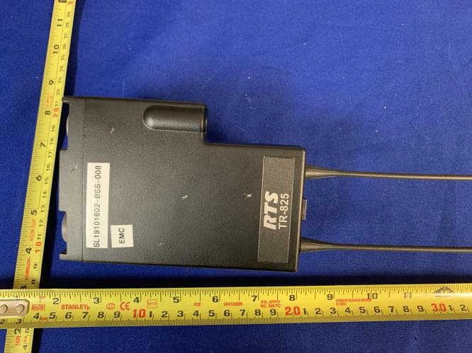
B5DM537
Mar 18, 2020Dual Receiver UHF Wireless Intercom Beltpack
Equipment Class
TLD - Licensed LPAS Device