BAB271000-322Millimeter Wave Radar
DENSO TEN Limited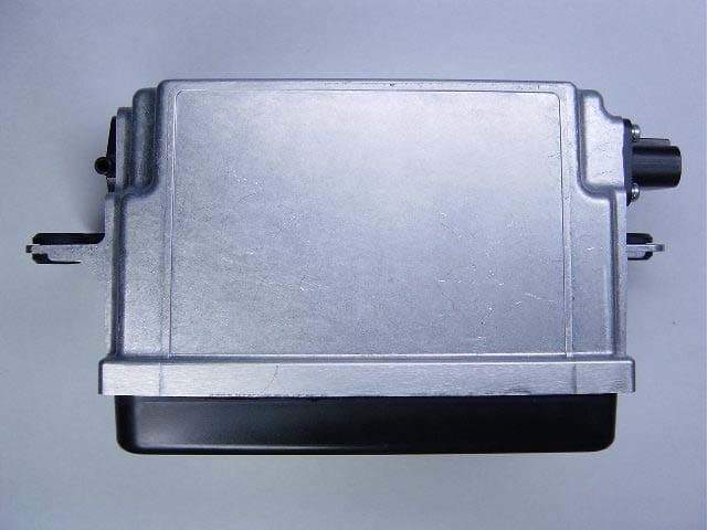
Click to zoom
Application Details
- Equipment Class
- FDS - Part 15 Field Disturbance Sensor
- Date of Grant
- Aug 25, 2004
- Application Purpose
- Original Equipment
- Date of Application
- Aug 25, 2004
- Equipment Note
- Millimeter Wave Radar
- Frequency Range
- 76000.00000000 - 77000.00000000
- Company
- DENSO TEN Limited
- Country
- Japan
Documents & Files
Document Text
Text extracted from the exhibit documents filed with the FCC. Open a document above to read the original.
Users Manual
Re: Certification for FUJITSU 271000-322 Radar Model: 271000-322 FCC ID: BAB271000-322 IC: 2024B-271322 USER'S MANUAL INFORMATION (PRELIMINARY) The User's Manual is in preparation. The following material will be contained in the manual: FCC ID: BAB271000-322 IC: 2024B-271322 This device complies with Part 15 of the FCC Rules and with RSS-210 of Industry Canada. Operation is subject to the following two conditions: (1) This device may not cause harmful interference, and (2) This device must accept any interference received, including interference that may cause undesired operation. WARNING: Changes or modifications not expressively approved by the party responsible for compliance could void the user's authority to operate the equipment. The term “IC:” before the radio certification number only signifies that Industry Canada technical specifications were met.
Cover Letter(s)
Re: Certification for FUJITSU 271000-322 Radar Model: 271000-322 FCC ID: BAB271000-322 IC: 2024B-271322 POWER OF ATTORNEY A letter granting Valdis V. Liepa the Power of Attorney is on file and can be provided when so requested. Re: Certification for FUJITSU 271000-322 Radar Model: 271000-322 FCC ID: BAB271000-322 IC: 2024B-271322 REQUEST FOR CONFIDENTIALITY Pursuant to 47 CRF 0.459, FUJITSU TEN LIMITED requests that a part of the subject application be held confidential. This comprises Exhibits (4) Block Diagram and Equipment Specification (5) Schematics (9) Internal Photos Note: DUT is epoxy sealed and removal of outer radome is not practical for the user, damage of device will occur. (10) Parts List & Parts Placement (12) Description of Operation FUJITSU TEN LIMITED has spent substantial effort in developing this product and it is one of the first of its kind in industry. Having the subject information easily available to "competition" would negate the advantage they have achieved by developing this product. Not protecting the details of the design will result in financial hardship. If there are any questions regarding this request, please contact me at the above address or call 734-483-4211, fax 734-647-2106 or e-mail [email protected]. Sincerely, Valdis V. Liepa Research Scientist University of Michigan August 18, 2004 Re: Certification for FUJITSU 271000-322 Radar Model: 271000-322 FCC ID: BAB271000-322 IC: 2024B-271322 STATEMENT OF MODIFICATIONS There were no modifications made to the DUT by this test laboratory. (Also see Section 3.1 of the attached Test Report). _____________________ Valdis V. Liepa Research Scientist Re: Certification for FUJITSU 271000-322 Radar Model: 271000-322 FCC ID: BAB271000-322 IC: 2024B-271322 GENERAL PRODUCT INFORMATION The device, for which certification is pursued, has been designed by: FUJITSU TEN LIMITED 2-28, Gosyo-dori, 1-chome, Hyogo-ku, Kobe, 652-8510, Japan Naoto NISHIMURA, Engineering Support Department. Research & Development. Group Tel: +81-78-682-2159 Fax: +81-78-671-7160 It will be manufactured by: Naoto NISHIMURA, Engineering Support Department. Research & Development. Group Tel: +81-78-682-2159 Fax: +81-78-671-7160 Canadian Contact: Fujitsu Ten Canada, Inc. 1149 Bellamy Road N. Unit 1, Scarborough, Ontario M1H 1H7 Tetsuya Yamamoto 416-431-9332 416-431-1745 [email protected]
Cover Letter(s)
American Telecommunications Certification Body Inc. 6731 Whittier Ave, McLean, VA 22101 August 23, 2004 RE: Fujitsu Ten Limited FCC ID: BAB271000-322 After a review of the submitted information, I have a few comments on the above referenced Application. 1) Is a photograph of the PCB layout Photo-2 (RF-unit solder-side) available without the metal “bar” across the board? 2) It appears that only part of the RF schematics may have been provided. Please explain and/or provide as necessary. 3) Please explain the difference between the 221.7 MHz bandwidth measured and the CW bandwidth shown in the report. It appears that the emissions were not adjusted by 10 log (EWB/RBW). Please correct or explain why this was not necessary. 4) Figure 5.3 appears to be measuring between the incorrect points. 5) Please add labels to Plots 5.5 similar to last report. 6) For 9.654 GHz, 18-26 GHz, and 40-76 GHz measurements show in Table 5.1 & 5.2, please explain compliance to 15.35 for limiting peak emissions. 7) Test equipment does not appear to show any measurement antennas for 60 – 75 GHz. 8) Please correct the IC form from radar device to FDS device. Timothy R. Johnson Examining Engineer mailto: [email protected] The items indicated above must be submitted before processing can continue on the above referenced application. Failure to provide the requested information may result in application termination. Correspondence should be considered part of the permanent submission and may be viewed from the Internet after a Grant of Equipment Authorization is issued. Please do not respond to this correspondence using the email reply button. In order for your response to be processed expeditiously, you must submit your documents through the AmericanTCB.com website. Also, please note that partial responses increase processing time and should not be submitted. Any questions about the content of this correspondence should be directed to the sender.
Cover Letter(s)
August 23, 2004 RE: Fujitsu Ten Limited FCC ID: BAB271000-322 The following is in response to comments on the above referenced Application. 1) Is a photograph of the PCB layout Photo-2 (RF-unit solder-side) available without the metal “bar” across the board? A photograph has been requested, and if available that photo will be provided. However, please note that this particular metal assembly is the mounting structure / heatsink of the MMIC, and separation of the ground metal from the device will likely destroy the MMIC. (This may be liked to removing the packaging from an IC.) No recognizable components will lye between the metal structure and the MMIC wafer, as this structure simply acts as a heatsink for the components within the MMIC structure. 2) It appears that only part of the RF schematics may have been provided. Please explain and/or provide as necessary. A request has been made with the manufacturer for more complete schematics of the RF subsection, and if available they will be provided. However, much of the high frequency RF sub- system is enclosed in the MMIC device; custom manufactured for this application and pre- packaged as the PCB RF UNIT. Since, in general, RF schematics of RFIC’s are not required during certification (only block diagram information), it may be expected that the schematics for a similar MMIC structure (which may be the property of a third party vendor) also would not be required. Please comment on the requirement for RF schematics of RFIC’s and MMIC’s during the certification process so that we may proceed in acquiring the schematics requested. 3) Please explain the difference between the 221.7 MHz bandwidth measured and the CW bandwidth shown in the report. It appears that the emissions were not adjusted by 10 log (EWB/RBW). Please correct or explain why this was not necessary. 221.7 MHz is the max-held measurement of total chirp/CW bandwidth while in the standard FM(chirp)/CW modulation mode. It does not represent the instantaneous bandwidth (EBW) of the chirp/CW radar. The test report lists the instantaneous EBW, which is demonstrated to be less than the input bandwidth of the Spectrum Analyzer. 4) Figure 5.3 appears to be measuring between the incorrect points. Yes, the markers in the plot are not on the appropriate signals. However, the correct period of 200 ms was measured during testing and is the value reported in the report. 5) Please add labels to Plots 5.5 similar to last report. The label has been modified. 6) For 9.654 GHz, 18-26 GHz, and 40-76 GHz measurements show in Table 5.1 & 5.2, please explain compliance to 15.35 for limiting peak emissions. For all bands listed, peak measurements were first made. When no emissions were observed, the spectrum analyzer was setup for average measurement in order to demonstrate compliance with the average limits. Please note that no emissions greater than the system noise floor were observed in these bands. 7) Test equipment does not appear to show any measurement antennas for 60 – 75 GHz. The test report has been corrected to list the appropriate equipment. Our apologies for the clerical error. 8) Please correct the IC form from radar device to FDS device. The IC Form has been corrected.
External Photos
External Photo Confidential Right side Front side Left side Underside Backside Upper surface Confidential External Photo (Expansion of a connector part)
ID Label/Location Info
Confidential ID label Confidential ID label Location
RF Exposure Info
(2) The minimum separation distance calculated following FCC OET Bulletin 65 is calculated as follows, where S is power density, Smeas (3m) = -27.8 dBm/cm 2 (pk; from Table 5.2, ave + duty factor) = 0.00166 mW/cm 2 = 12.2 dBm/m 2 EIRP = Smeas (3m) x 4ʌR 2 = 12.2 + 20.5 = 32.7 dBm = 1862 mW = 1.86 W ERP = EIRP – 2.15 = 32.7 – 2.15 = 30.55 dBm = 1135 mW = 1.14 W Thus, the power density at 20 cm becomes S(mW/cm 2 ) = EIRP(mW)/(4ʌ R(cm) 2 ) = 0.37 mW/cm 2 NOTE: (1) Under no circumstances is the ERP of this device greater than 3W, as required by 2.1091 and the FCC mm-wave accepted test procedures, (2) The DUT is only operating when the vehicle is in motion
Test Report
The University of Michigan Radiation Laboratory 3228 EECS Building Ann Arbor, MI 48109-2122 Tel: (734) 764-0500 Measured Radio Frequency Emissions From Fujitsu Ten 76 GHz Adaptive Cruse Control Radar Model(s): 271000-280, 271000-322 Report No. 415031-220 August 6, 2004 Copyright © 2004 For: TUV America Inc. 19333 Wild Mountain Road Taylor Falls, MN 55084-0298 Contact: Joel Schneider [email protected] Tel: 651-638-0297 Fax: 651-638-02978 PO: CE16852 Tests supervised by: Measurements made by: Report approved by: _____________________ Valdis V. Liepa Valdis V. Liepa Joseph D. Brunett Research Scientist Summary Tests for compliance with FCC Regulations, according to Part 15.253, and with Industry Canada Regulations, RSS-210, were performed on Fujitsu Ten 76 GHz Adaptive Cruse Control Radar. In testing performed during July 16 through 27, 2004, the device tested met the emission limits at the fundamental by 22.1 dB, at the harmonics by 47.8 dB, and at spurious by 3.4 dB. For RF Health Hazard, the maximum RF field at a 20 cm distance was calculated to be 0.37 mW/cm 2 . The DUT is designed for automotive applications, and as such, digital radiated and conducted emissions are not subject to regulation. 2 1. Introduction Fujitsu 76 GHz Adaptive Cruse Control Radar was tested for compliance with FCC Regulations, Part 15, adopted under Docket 87-389, April 18, 1989, and with Industry Canada RSS-210, Issue 5, dated November 10, 2001. The tests were performed at the University of Michigan Radiation Laboratory Willow Run Test Range following the procedures described in ANSI C63.4-1992 "Methods of Measurement of Radio-Noise Emissions from Low-Voltage Electrical and Electronic Equipment in the Range of 9 kHz to 40 GHz" and the new FCC Section 15.253, "Operation within the bands 46.7-46.9 GHz and 76.0-77.0 GHz". The Site description and attenuation characteristics of the Open Site facility are on file with FCC Laboratory, Columbia, Maryland (FCC Reg. No: 91050) and with Industry Canada, Ottawa, ON (File Ref. No: IC 2057). 2. Test Equipment Used The pertinent test equipment commonly used in our facility for measurements is listed in Table 2.1 below. The middle column identifies the specific equipment used in these tests. Table 2.1. Test Equipment. Test Instrument Eqpt. Used Manufacturer/Model Spectrum Analyzer (0.1-1500 MHz) Hewlett-Packard, 182T/8558B Spectrum Analyzer (9kHz-22GHz) Hewlett-Packard 8592L, SN: 3710A00856 Spectrum Analyzer (9kHz-26GHz) X Hewlett-Packard 8593E, SN: 3412A01131 Spectrum Analyzer (9kHz-26GHz) X Hewlett-Packard 8563E, SN: 3310A01174 Spectrum Analyzer (9kHz-40GHz) X Hewlett-Packard 8564E, SN: 3745A01031 Power Meter Hewlett-Packard, 432A Power Meter Anritsu, ML4803A/MP Harmonic Mixer (40-60 GHz) X Hewlett-Packard 11970U, SN: 2332A00500 Harmonic Mixer (60-90 GHz) X Pacific Millimeter Prod., VN, SN: 47 Harmonic Mixer (75-110 GHz) X Hewlett-Packard 11970W, SN: 2521A00179 Harmonic Mixer (140-220 GHz) X Pacific Millimeter Prod., GMA, SN: 26 X-band horn (8.2- 12.4 GHz) Narda 640 X-band horn (8.2- 12.4 GHz) X Scientific Atlanta , 12-8.2, SN: 730 K-band horn (18-26.5 GHz) X FXR, Inc., K638KF Ka-band horn (26.5-40 GHz) X FXR, Inc., U638A U-band horn (40-60 GHz) X Custom Microwave, HO19 V-band horn (60-90 GHz) X Custom Microwave, HO12 W-band horn (75-110 GHz) X Custom Microwave, HO10 G-band horn (140-220 GHz) X Custom Microwave, HO5R Bicone Antenna (30-250 MHz) X University of Michigan, RLBC-1 Bicone Antenna (200-1000 MHz) X University of Michigan, RLBC-2 Dipole Antenna Set (30-1000 MHz) University of Michigan, RLDP-1,-2,-3 Dipole Antenna Set (30-1000 MHz) EMCO 2131C, SN: 992 Active Rod Antenna (30 Hz-50 MHz) EMCO 3301B, SN: 3223 Active Loop Antenna (30 Hz-50 MHz) EMCO 6502, SN:2855 Ridge-horn Antenna (300-5000 MHz) X University of Michigan Amplifier (5-1000 MHz) Avantek, A11-1, A25-1S Amplifier (5-4500 MHz) X Avantek Amplifier (4.5-13 GHz) X Avantek, AFT-12665 Amplifier (6-16 GHz) X Trek LISN (50 μH) University of Michigan Signal Generator (0.1-2060 MHz) Hewlett-Packard, 8657B Signal Generator (0.01-20 GHz ) X Hewlett-Packard, 8550B / 83592A 3 3. Configuration and Identification of Device Under Test The Device Under Test (DUT) is a 76 GHz Short Range Radar. It is a Tx/Rx 457 kHz (or 10 MHz) switched FM and CW device. The triangular frequency chirp at 353 Hz provides range information. Mechanical antenna scanning at 5 Hz is used to obtain target angular resolution. The RF power source is 5 dBm (typ.) based on a 9.6 GHz reference. The DUT is a basic radar unit; additional signal processing and controlling are done by other processors on the vehicle. When installed on a vehicle, the device will operate (transmit) only when the vehicle is in motion, i.e., typ. 20 MPH and above. The size of the DUT is 13(W) x 7(H) x 10(D) cm with a single connector on one side. For testing, a laptop was used to control the format of modulation. This included: (a) normal mode (CW, FM, and switching), (b) CW with 457 kHz switching, (c) CW only, plus others that were not used in these tests. Nominal operating voltage is 13.8 VDC; for testing this was supplied by a laboratory style power supply. The DUT was manufactured by Fujitsu Ten Limited; 2-28, Gosho-dori 1-chome; Hyogo-Ku, Kobe 652-8510; Japan. It is identified as: Fujitsu 76 GHz Adaptive Cruse Control Radar Model(s): 271000-280, 271000-322 S/N: FCC SAMPLE B (standard unit) S/N: FCC SAMPLE A (fixed antenna unit) FCC ID(s): BAB271000-280, BAB271000-322 IC(s): 2024B-271280, 2024B-271280 Two model 271000-280 devices were provided: one is a standard model, and the other has the antenna scanning mechanically disabled. Both units were used in testing, depending on what data (information) was needed. The model 271000-322 device was not tested, as the only difference between it and the 271000-280 is that the yaw rate sensor has been depopulated. Depopulation of the yaw rate sensor should have no affect on the DUT emissions as explained in related letters provided …
Text truncated - open the document above for the full version.
Contact Information
Applicant
Kaoru Abe(Department General Manager)
Technical Contact
University of Michigan/EECSValdis V Liepa
[email protected]734-483-4211
1301 Beal Ave. · Ann Arbor, Michigan · United States
Non-Technical Contact
University of Michigan/EECSValdis V Liepa
[email protected]734-483-4211
Test Firm
University of MichiganValdis Liepa
Technical Specifications
| # | Rule Parts | Frequency Range | Power Output |
|---|---|---|---|
| 1 | 15.253 | 76.00 GHz - 77.00 GHz | - |
Other Applications from DENSO TEN Limited
BABTN0052E
May 26, 2026Car Audio
Equipment Class
CXX - Communications Rcvr for use w/ licensed Tx and CBsBABTN0051A
Apr 10, 2026Car Navigation
Equipment Class
CXX - Communications Rcvr for use w/ licensed Tx and CBs
BABTN0046A
Feb 12, 2024Car Audio
Equipment Class
CXX - Communications Rcvr for use w/ licensed Tx and CBs
BABTN0040B
Jul 23, 2023Car Audio
Equipment Class
DTS - Digital Transmission System
BABTN0040A
Jul 23, 2023Car Audio
Equipment Class
CXX - Communications Rcvr for use w/ licensed Tx and CBs