BBD8-1ACRF Power Amplifier
TPL Communications Inc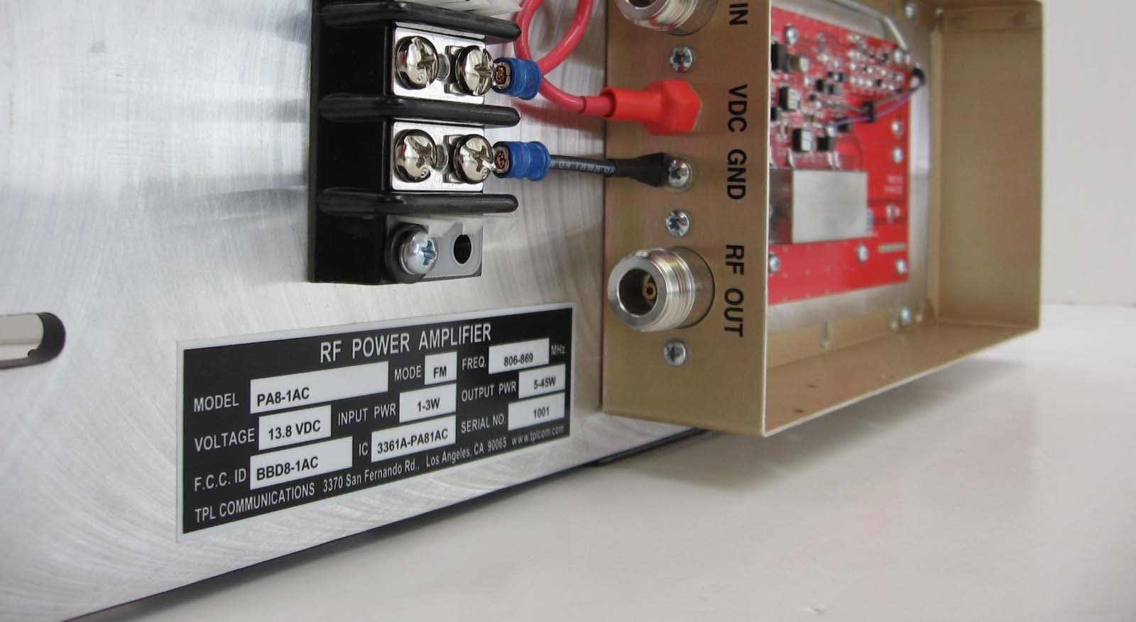
Click to zoom
Application Details
- Equipment Class
- AMP - Amplifier
- Date of Grant
- Mar 31, 2010
- Application Purpose
- Original Equipment
- Date of Application
- Mar 31, 2010
- Equipment Note
- RF Power Amplifier
- Frequency Range
- 806.00000000 - 869.00000000
- Company
- TPL Communications Inc
- Country
- United States
Documents & Files
Document Text
Text extracted from the exhibit documents filed with the FCC. Open a document above to read the original.
Users Manual
USER’S MANUAL UHF HIGH BAND CONTINUOUS DUTY RF POWER AMPLIFIER PA8 - 1AC 3370 SAN FERNANDO ROAD, #206 LOS ANGELES, CA 90065 TEL: (323) 256-3000 FAX: (323) 254-321 E-mail: [email protected]. TABLE OF CONTENTS I. PRODUCT DESCRIPTION II. GENERAL SPECIFICATION III. OPTIONS IV. CAUTION V. OPERATING PRECAUTIONS VI. INSTALLATION VII. WARRANTY VIII. SERVICE I. PRODUCT DESCRIPTION The PA8-1AC model is a UHF high band continuous duty RF power amplifier intended for use in repeater applications. This amplifier can deliver RF power from 5 to 45 watts when driven with 1.0 to 3.0 watts and it will cover the frequency range from 806 MHz to 869 MHz. These amplifiers are designed to be installed in a 196inch rack. The amplifier’s dimensions are 19” W x 5 ¼” H x 4 ½” D and the weight is 8 lbs. Figure 1. II. GENERAL SPECIFICATIONS ELECTRICAL SPECIFICATIONS @ V DC = 13.8 VDC. Nom., T = 25° C; Parameter Symbol Min Typ Max Unit Condition Frequency Range BW 806.000 869.000 MHz Operating bandwidth within range OBW 63.0 MHz Input Power P IN 1.0 3.0 Watt Output Power P OUT 5 45 50 Watt Output Flatness >P OUT ±0.5 dB Within OBW Small Signal Gain G 9 10 dB Harmonic Emissions Har 660 dBc P OUT = 45 W Spurious Emissions Spur 660 dBc P OUT = 45 W Operating Voltage V DD 11 13.8 15 Volt DC Supply Current I DD 9 10 Amp DC Input VSWR S11 2 : 1 VSWR Operating Mode Mode CW/FM Impedance, Input Z IN 50 F Impedance, Output Z OUT 50 F Duty Cycle D 100 % per EIA/TIA66036C Receive Bypass Relay Not Included ENVIRONMENTAL CHARACTERISTICS Parameter Symbol Min Typ Max Unit Condition Operating Temperature T O 630 +60 °C Storage Temperature T S 630 +80 °C Operating Humidity H O 0 85 % relative, non6condensing Storage Humidity H S 0 95 % relative, non6condensing MECHANICAL PROPERTIES Parameter Value Units Limits Condition Dimensions 19”W x 5 1/4”H x 4 1/2” D inch max Weight 8 lb max RF Connectors, In/Out Type “N” DC Connector Terminal Block Cooling Forced Air (Fan) SPECIAL CHARACTERISTICS End6user accessible thru6hole multi turn potentiometer for adjusting output power from 5 W to 45 W. III. OPTIONS TPL Communication’ UHF high band continuous duty RF Power Amplifiers are available with several options: input, output, frequency ranges and configurations, special logos, etc., when specified at the time of order. We work closely with you, our customer, to develop products that are in complete compliance with your needs and specifications. NOTE: All TPL Standard UHF high band continuous duty RF power amplifiers are factory6tuned to the frequency specified at the time of order. Broader coverage is available. Contact TPL Communications for details. IV. CAUTION! Inspect the amplifier thoroughly upon receipt for visible damage. If any is noticed, please call TPL Communications at 800 HI POWER / (800)447 - 6937 or e6mail to [email protected] to request an RMA (Return Material Authorization) number. If purchased through a dealer or distributor, ask them to follow this procedure for best results. EXPENSIVE COMPONENTS MAY BE DESTROYED IF THE AMPLIFIER IS TURNED ON IN A DAMAGE CONDITION. FCC CERTIFICATION TPL Communications commercial amplifiers are FCC certified for the use in Land and Marine mobile/fixed services. The technician installing this amplifier must hold a General Radio Telephone permit and be familiar with the pertinent FCC rules and regulations. Harmonics and other spurious signals from this amplifier are attenuated according to the product specification or beyond FCC requirements. For further details consult the appropriate publications. V. OPERATING PRECAUTIONS CAUTION: This amplifier produces RF voltages that can cause painful and dangerous burns. Use caution! Connect and disconnect all RF connections with the drive power and DC power off. DRIVE POWER: RF power transistors, although quite rugged in most respects, are easily damaged by overdrive. Be careful not to overdrive the amplifier even momentarily (before applying any drive signal please check product specification for details). Higher6than6rated drive power may destroy transistors and VOID ANY WARRANTY. SUPPLY VOLTAGE: The maximum operating voltage is 15.0VDC. When using a DC power supply make sure that it is not adjusted above 15 volts. If it is possible for the voltage to go above 15 Volts for any reason, including failure of the power supply, install a “crowbar” circuit to prevent damage to the amplifier in the event of excess voltage. CASE TEMPERATURE High power can mean high temperatures. Mount the amplifier where air can freely circulate into the cooling fan and where clothing, blankets, etc. will not accidentally be placed over it. TERMINATIONS The efficiency of this amplifier will degrade if it is operates into anything but a 50 F load. Lowered efficiency may mean any or all of the following: lower power output, increased current drain, higher operating temperature and reduced lifetime. VI. INSTALLATION The PA8-1AC amplifiers are designed for mounting in a standard 196inch rack. When picking a location in the rack, considerations must be given to RF cable lengths as well as cooling. Mount the amplifier away from the sources of heat where dust and other debris are not likely to clog the cooling fan and as close to the antenna as practical. Keep coaxial cable runs short, avoiding sharp bends and pinching. Avoid loose connectors at the ends of the coaxial cables. The antenna should be matched to a VSWR better than 1.5:1 for best results. Higher VSWR will degrade the performance of the amplifier. 1. Connect the DC power using #14 AWG wiring if possible and certainly no lighter than #16 AWG. To avoid a possible fire or other possible damage, make sure a fuse or circuit breaker is installed at the power supply end of the wires. Use the same size fuse as the amplifier’s fuse. 2. Connect the antenna to the “RF OUT” terminal with a 50F coaxial cable and type “N” male plug. 3. Turn off your radio transmitter. Connect it to the “RF INPUT” terminal with a 50F coaxial …
Text truncated - open the document above for the full version.
Test Report
FCC CFR47 PART 90, SUBPART I CERTIFICATION TEST REPORT FOR RF POWER AMPLIFIER MODEL NUMBER: PA8-1AC FCC: BBD8-1AC REPORT NUMBER: 10U12123-1 ISSUE DATE: MARCH 24, 2010 Prepared for TPL COMMUNICATIONS, INC. 3370 SAN FERNANDO ROAD, SUITE 206 LOS ANGELES, CA 90065, USA Prepared by COMPLIANCE CERTIFICATION SERVICES 47173 BENICIA STREET FREMONT, CA 94538, USA TEL: (510) 771-1000 FAX: (510) 661-0888 REPORT NO: 10U13123-1 DATE: MARCH 24, 2010 EUT: RF POWER AMPLIFIER FCC ID: BBD8-1AC Page 2 of 33 COMPLIANCE CERTIFICATION SERVICES DOCUMENT NO: CCSUP4031A 47173 BENICIA STREET, FREMONT, CA 94538, USA TEL: (510) 771-1000 FAX: (510) 661-0888 This report shall not be reproduced except in full, without the written approval of CCS. Revision History Rev. Issue Date Revisions Revised By --- 03/24/10 Initial Issue T. Chan REPORT NO: 10U13123-1 DATE: MARCH 24, 2010 EUT: RF POWER AMPLIFIER FCC ID: BBD8-1AC Page 3 of 33 COMPLIANCE CERTIFICATION SERVICES DOCUMENT NO: CCSUP4031A 47173 BENICIA STREET, FREMONT, CA 94538, USA TEL: (510) 771-1000 FAX: (510) 661-0888 This report shall not be reproduced except in full, without the written approval of CCS. TABLE OF CONTENTS 1. ATTESTATION OF TEST RESULTS.................................................................................... 4 2. TEST METHODOLOGY ........................................................................................................ 5 3. FACILITIES AND ACCREDITATION.................................................................................... 5 4. CALIBRATION AND UNCERTAINTY .................................................................................. 5 4.1. MEASURING INSTRUMENT CALIBRATION ................................................................ 5 4.2. SAMPLE CALCULATION ............................................................................................... 5 4.3. MEASUREMENT UNCERTAINTY ................................................................................. 5 5. EQUIPMENT UNDER TEST ................................................................................................. 6 5.1. DESCRIPTION OF EUT ................................................................................................. 6 5.2. MAXIMUM OUTPUT POWER ........................................................................................ 6 5.3. WORST-CASE CONFIGURATION AND MODE............................................................ 6 5.4. DESCRIPTION OF TEST SETUP .................................................................................. 7 6. TEST AND MEASUREMENT EQUIPMENT ......................................................................... 9 7. LIMITS AND RESULTS ...................................................................................................... 10 7.1. OCCUPIED BANDWIDTH ............................................................................................ 10 7.2. FM EMISSION LIMITATION......................................................................................... 14 7.3. MODULATION CHARACTERISTICS........................................................................... 18 7.4. RF POWER OUTPUT .................................................................................................. 18 7.5. VOLTAGE STABILITY.................................................................................................. 21 7.6. SPURIOUS EMISSION AT ANTENNA TERMINAL ..................................................... 22 7.7. FIELD STRENGTH OF SPURIOUS RADIATION ........................................................ 29 7.7.1. SPURIOUS RADIATION 30 – 1000 MHz.............................................................. 30 7.7.2. SPURIOUS RADIATION ABOVE 1GHz................................................................ 31 8. SETUP PHOTOS................................................................................................................. 32 REPORT NO: 10U13123-1 DATE: MARCH 24, 2010 EUT: RF POWER AMPLIFIER FCC ID: BBD8-1AC Page 4 of 33 COMPLIANCE CERTIFICATION SERVICES DOCUMENT NO: CCSUP4031A 47173 BENICIA STREET, FREMONT, CA 94538, USA TEL: (510) 771-1000 FAX: (510) 661-0888 This report shall not be reproduced except in full, without the written approval of CCS. 1. ATTESTATION OF TEST RESULTS COMPANY NAME: TPL COMMUNICATIONS, INC. 3370 SAN FERNANDO ROAD, SUITE 206 LOS ANGELES, CA 90065 USA EUT DESCRIPTION: RF POWER AMPLIFIER MODEL: PA3-1FE SERIAL NUMBER: 1002 DATE TESTED: MARCH 22-24, 2010 APPLICABLE STANDARDS STANDARD TEST RESULTS FCC PART 90 SUBPART I PASS Compliance Certification Services, Inc. (CCS) tested the above equipment in accordance with the requirements set forth in the above standards. All indications of Pass/Fail in this report are opinions expressed by CCS based on interpretations and/or observations of test results. Measurement Uncertainties were not taken into account and are published for informational purposes only. The test results show that the equipment tested is capable of demonstrating compliance with the requirements as documented in this report. Note: The results documented in this report apply only to the tested sample, under the conditions and modes of operation as described herein. This document may not be altered or revised in any way unless done so by CCS and all revisions are duly noted in the revisions section. Any alteration of this document not carried out by CCS will constitute fraud and shall nullify the document. This report must not be used by the client to claim product certification, approval, or endorsement by NVLAP, NIST, any agency of the Federal Government, or any agency of any government. Approved & Released For CCS By: Tested By: THU CHAN CHIN PANG ENGINEERING MANAGER EMC ENGINEER COMPLIANCE CERTIFICATION SERVICES COMPLIANCE CERTIFICATION SERVICES REPORT NO: 10U13123-1 DATE: MARCH 24, 2010 EUT: RF POWER AMPLIFIER FCC ID: BBD8-1AC Page 5 of 33 COMPLIANCE CERTIFICATION SERVICES DOCUMENT NO: CCSUP4031A 47173 BENICIA S…
Text truncated - open the document above for the full version.
Test Setup Photos
REPORT NO: 10U13123-1 DATE: MARCH 24, 2010 EUT: RF POWER AMPLIFIER FCC ID: BBD8-1AC Page 32 of 33 COMPLIANCE CERTIFICATION SERVICES DOCUMENT NO: CCSUP4031A 47173 BENICIA STREET, FREMONT, CA 94538, USA TEL: (510) 771-1000 FAX: (510) 661-0888 This report shall not be reproduced except in full, without the written approval of CCS. 8. SETUP PHOTOS ANTENNA PORT CONDUCTED RF MEASUREMENT SETUP RADIATED RF MEASUREMENT SETUP ANTENNA PORT CONDUCTED PHOTO RADIATED FRONT PHOTO REPORT NO: 10U13123-1 DATE: MARCH 24, 2010 EUT: RF POWER AMPLIFIER FCC ID: BBD8-1AC Page 33 of 33 COMPLIANCE CERTIFICATION SERVICES DOCUMENT NO: CCSUP4031A 47173 BENICIA STREET, FREMONT, CA 94538, USA TEL: (510) 771-1000 FAX: (510) 661-0888 This report shall not be reproduced except in full, without the written approval of CCS. END OF REPORT RADIATED BACK PHOTO
Contact Information
Applicant
Lenny Uchenik(VP, Engineering)
Technical Contact
COMPLIANCE CERTIFICATION SERVICESThu Chan
[email protected](510) 771-1000
47173 Benicia Street · Fremont, California · United States
Non-Technical Contact
COMPLIANCE CERTIFICATION SERVICESThu Chan
[email protected](510) 771-1000
Test Firm
Compliance Certification ServicesBarbara Judge
Technical Specifications
| # | Rule Parts | Frequency Range | Power Output | Emission | Tolerance |
|---|---|---|---|---|---|
| 1 | 90 | 806 MHz - 869 MHz | 50.2 W | F3E | Amp |
Other Applications from TPL Communications Inc
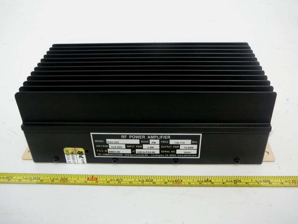
BBD3-60
Oct 09, 2012RF Power Amplifier
Equipment Class
AMP - Amplifier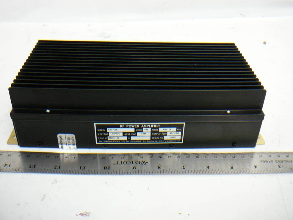
BBD3-125
Oct 01, 2012RF Power Amplifier
Equipment Class
AMP - Amplifier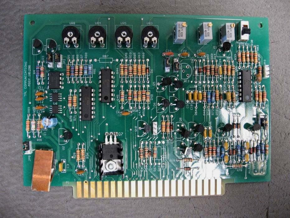
BBDPA9096-350
Oct 27, 2011RF Power Amplifier
Equipment Class
AMP - Amplifier
BBD1-1AEL
Aug 13, 2007RF Power Amplifier
Equipment Class
AMP - Amplifier
BBDRC31FE
Jan 16, 2007RF Power Amplifier
Equipment Class
AMP - Amplifier