BBDPA9096-350RF Power Amplifier
TPL Communications Inc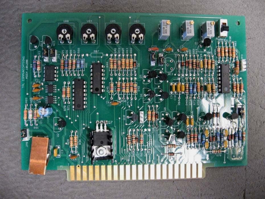
Click to zoom
Application Details
- Equipment Class
- AMP - Amplifier
- Date of Grant
- Oct 27, 2011
- Application Purpose
- Original Equipment
- Date of Application
- Oct 27, 2011
- Equipment Note
- RF Power Amplifier
- Frequency Range
- 920.00000000 - 940.00000000
- Company
- TPL Communications Inc
- Country
- United States
Documents & Files
Document Text
Text extracted from the exhibit documents filed with the FCC. Open a document above to read the original.
Users Manual
USER MANUAL HMS SERIES RF POWER AMPLIFIER 3370 SAN FERNANDO RD., #206 LOS ANGELES, CA 90065 TEL: (323)256-3000 FAX: (323)254-3210 www.tplcom.com TABLE OF CONTENTS PRODUCT DESCRIPTION .................................................................................. 2 GENERAL SPECIFICATIONS.............................................................................. 2 OPERATING PRECAUTIONS.............................................................................. 3 INSTALLATION.................................................................................................... 4 MAINTENANCE ................................................................................................... 4 METERING AND INDICATORS........................................................................... 5 OPERATOR ADJUSTMENTS.............................................................................. 6 REMOTE MONITORING...................................................................................... 8 APPENDIX I ......................................................................................................... 9 HMS ILLUSTRATION......................................................................................... 10 WARRANTY....................................................................................................... 12 Page 1 PRODUCT DESCRIPTION The HMS series of TPL power amplifiers are intended for use in base station or repeater applications. They are high power units and in various configurations cover the frequency range extending form Low Band VHF to 960 MHz. An HMS series RF power amplifier is a self contained unit which allows operation, metering, and remote monitoring of all parameters of an RF power amplifier. Its major components are: enclosure, front panel, rear panel, power amplifier, power supply, cooling fans, metering, control, and monitoring circuits. The entire assembly is designed to be installed in a nineteen inch rack. For operator convenience views of the front and rear of the amplifier are presented in the illustrations section of APPENDIX 1. GENERAL SPECIFICATIONS MODEL: PA9096-350 FREQUENCY RANGE: 920-940 MHz POWER INPUT: 100 mW – 50 W (model dependent) NOMINAL POWER OUTPUT: 350 watts EIA DUTY CYCLE: 100% / Continuous. MODULATION MODE: FM. IN/OUT RF CONNECTORS: Type “N” – IN; 7/16 DIN - OUT OPERATING TEMPERATURE RANGE: -20º to +50º Celsius. OPERATING VOLTAGE: 110 VAC Standard, 220 VAC Optional. HARMONICS and SPURIOUS EMISSION ATTENUATION: Meets or exceed FCC type acceptance requirements. CIRCUIT PROTECTION: Provided by the circuit breaker. REMOTE MONITORING: A DB-25 connector for remote access to metering and indicators is a standard feature on all HMS RF amplifiers (See Table 1). OPERATING HUMIDITY: 0%-85% RH (Non-condensing). STORAGE HUMIDITY: 0% -95% RH (Non-condensing). Page 2 CAUTION! Check the amplifier upon receipt for visible damage. If any is noticed, please call TPL at 800 HI POWER to request an RMA number (Return Material Authorization). If purchased through a dealer, ask them to follow this procedure for best results. EXPENSIVE COMPONENTS MAY BE DESTROYED IF THE AMPLIFIER IS TURNED ON IN A DAMAGED CONDITION. OPERATING PRECAUTIONS CAUTION: This amplifier produces RF voltages that can cause painful and dangerous RF burns. Use caution! Connect and disconnect all RF connectors with the AC power and drive power off. DRIVE POWER: RF power transistors, although quite rugged in most respects, are easily damaged by overdrive. Be careful no to overdrive this amplifier, even for an instant. Higher than rated drive power may destroy the transistors and VOID ANY WARRANTY. TERMINATIONS: The parameters of this amplifier will degrade if it is operated into anything but a 50 Ohm load. That may mean any, or all, of the following; lower power output, increased current drain, higher operating temperature, lower efficiency and reduced lifetime. Page 3 INSTALLATION This unit is designed for mounting in a standard nineteen inch rack. When picking a location in the rack, considerations must be given to the lengths of the RF coaxial cable, as well as cooling. Mount the unit where dust and other debris are not likely to clog the cooling fans. Avoid mounting the amplifier directly above hot pieces of equipment that could artificially raise the amplifier temperature. Connect the radio transmitter to the “RF INPUT” N connector and an antenna to the “RF OUTPUT” 7/16 DIN connector on the amplifier. Use 50 Ohm coaxial cable with appropriate RF power rating. Plug the AC line cord into the system AC power receptacle. For safety, make sure the rack and all equipment connecting to the amplifier have proper AC grounds. Do not rely on coaxial cable shields for AC grounding. Assure the installation has proper lightning protection. MAINTENANCE There are two maintenance tasks to be performed on the TPL Communications HMS Series RF Amplifiers. These tasks are listed below. 1.) Perform regular inspections of the air intake and exhaust fans. Clean or clear any dust or debris that may have collected. This will prevent the amplifier from overheating. 2.) Every month record the data displayed on the HMS status display on the Front Panel Meter Reading Data Sheet in APPENDIX 1 of the HMS users manual. This will aid the technicians in servicing the amplifier should a problem develop. Page 4 METERING AND INDICATORS The following signals and voltages are indicated on the front panel HMS status meter, (a liquid crystal display). The parameters to be monitored are selectable via the front panel momentary contact toggle switch. The status meter has two lines of text. The top line indicates the parameter to be measured while the bottom line indicates the measured value and its units. Refer to the front panel drawing in the illustrations section for the location of the meter and switch. The following is a list of display positions and functions. Display Position Function HMS STATUS . . . . . . .…
Text truncated - open the document above for the full version.
ID Label/Location Info
TPL Communications, Inc. FCC ID: BBDPA9096-350 Report Number: R1105201 Page 32 of 44 FCC Part 22/24/90/101 Test Report 10 EXHIBIT A - FCC ID LABELING AND WARNING STATEMENT 10.1 FCC ID Label Requirement FCC §2.925 Identification of equipment (a) Each equipment covered in an application for equipment authorization shall bear a nameplate or label listing the following: (1) FCC Identifier consisting of the two elements in the exact order specified in §2.926. The FCC Identifier shall be preceded by the term FCC ID in capital letters on a single line, and shall be of a type size large enough to be legible without the aid of magnification. Example: FCC ID: XXX123 Where: XXX—Grantee Code, 123—Equipment Product Code 10.2 FCC ID Label Contents FCC ID: XXX-XXXXXX TPL Communications, Inc. FCC ID: BBDPA9096-350 Report Number: R1105201 Page 33 of 44 FCC Part 22/24/90/101 Test Report 10.3 Suggested Label Location on EUT Label here
Internal Photos
TPL Communications, Inc. FCC ID: BBDPA9096-350 Report Number: R1105201 Page 39 of 44 FCC Part 22/24/90/101 Test Report 12.7 EUT – Cover off View 12.8 EUT – Internal Wiring View TPL Communications, Inc. FCC ID: BBDPA9096-350 Report Number: R1105201 Page 40 of 44 FCC Part 22/24/90/101 Test Report 12.9 EUT – Control Board Front View 12.10 EUT – Control Board Back View TPL Communications, Inc. FCC ID: BBDPA9096-350 Report Number: R1105201 Page 41 of 44 FCC Part 22/24/90/101 Test Report 12.11 EUT – Current Sensor Front View 12.12 EUT – Current Sensor Back View TPL Communications, Inc. FCC ID: BBDPA9096-350 Report Number: R1105201 Page 42 of 44 FCC Part 22/24/90/101 Test Report 12.13 EUT – Display Board Front View 12.14 EUT – Display Board Back View TPL Communications, Inc. FCC ID: BBDPA9096-350 Report Number: R1105201 Page 43 of 44 FCC Part 22/24/90/101 Test Report 12.15 EUT – Dual Direction Coupler View 12.16 EUT – RF Input Sensor View TPL Communications, Inc. FCC ID: BBDPA9096-350 Report Number: R1105201 Page 44 of 44 FCC Part 22/24/90/101 Test Report 12.17 EUT – Voltage Regulator View ***** End of Report *****
Test Report
Note: This test report is prepared for the customer shown above and for the device described herein. It may not be duplicated or used in part without prior written consent from Bay Area Compliance Laboratories Corp. This report must not be used by the customer to claim product certification, approval, or endorsement by NVLAP*, NIST, or any agency of the Federal Government. * This report may contain data that are not covered by the NVLAP accreditation and are marked with an asterisk “*” (Rev.2) FCC PART 22, 24, 90, 101 TEST AND MEASUREMENT REPORT For TPL Communications Inc. 3370 San Fernando Road, Unit 206 Los Angeles, CA 90065, USA FCC ID: BBDPA9096-350 Report Type: Original Report Product Type: RF Power Amplifier Test Engineer: Kevin Li Report Number: R1105201 Report Date: 2011-09-22 Reviewed By: Victor Zhang EMC/RF Lead Prepared By: (84) Bay Area Compliance Laboratories Corp. 1274 Anvilwood Avenue, Sunnyvale, CA 94089, USA Tel: (408) 732-9162 Fax: (408) 732 9164 TPL Communications, Inc. FCC ID: BBDPA9096-350 Report Number: R1105201 Page 2 of 44 FCC Part 22/24/90/101 Test Report TABLE OF CONTENTS 1 GENERAL INFORMATION .............................................................................................................................. 5 1.1 PRODUCT DESCRIPTION FOR EQUIPMENT UNDER TEST (EUT) ........................................................................ 5 1.2 MECHANICAL DESCRIPTION OF EUT............................................................................................................... 5 1.3 OBJECTIVE...................................................................................................................................................... 5 1.4 RELATED SUBMITTAL(S)/GRANT(S) ................................................................................................................ 5 1.5 TEST METHODOLOGY...................................................................................................................................... 6 1.6 MEASUREMENT UNCERTAINTY....................................................................................................................... 6 1.7 TEST FACILITY................................................................................................................................................ 6 2 SYSTEM TEST CONFIGURATION ................................................................................................................. 7 2.1 JUSTIFICATION................................................................................................................................................. 7 2.2 EUT EXERCISE SOFTWARE............................................................................................................................. 7 2.3 EQUIPMENT MODIFICATIONS........................................................................................................................... 7 2.4 SPECIAL EQUIPMENT....................................................................................................................................... 7 2.5 LOCAL SUPPORT EQUIPMENT.......................................................................................................................... 7 2.6 EUT INTERNAL CONFIGURATION DETAILS..................................................................................................... 7 2.7 EXTERNAL I/O CABLING LIST AND DETAILS................................................................................................... 8 3 SUMMARY OF TEST RESULTS ...................................................................................................................... 9 4 FCC §2.1046 – RF OUTPUT POWER.............................................................................................................. 10 4.1 APPLICABLE STANDARDS.............................................................................................................................. 10 4.2 TEST PROCEDURE.......................................................................................................................................... 10 4.3 TEST SETUP BLOCK DIAGRAM...................................................................................................................... 10 4.4 TEST EQUIPMENT LIST AND DETAILS............................................................................................................ 11 4.5 TEST ENVIRONMENTAL CONDITIONS............................................................................................................ 11 4.6 TEST RESULTS............................................................................................................................................... 11 5 FCC §2.1047 - MODULATION CHARACTERISTIC ................................................................................... 12 5.1 APPLICABLE STANDARD................................................................................................................................12 5.2 TEST RESULT................................................................................................................................................. 12 6 FCC §2.1049 – OCCUPIED BANDWIDTH & EMISSION MASK............................................................... 13 6.1 APPLICABLE STANDARD................................................................................................................................13 6.2 TEST PROCEDURE.......................................................................................................................................... 13 6.3 TEST ENVIRONMENTAL CONDITIONS............................................................................................................ 13 6.4 TEST EQUIPMENT LIST AND DETAILS............................................................................................................ 14 6.5 TEST RESULTS................................................................…
Text truncated - open the document above for the full version.
Test Setup Photos
TPL Communications, Inc. FCC ID: BBDPA9096-350 Report Number: R1105201 Page 34 of 44 FCC Part 22/24/90/101 Test Report 11 EXHIBIT B - TEST SETUP PHOTOGRAPHS 11.1 Radiated Emissions - Front View (Below 1 GHz) 11.2 Radiated Emissions - Rear View (Below 1 GHz) TPL Communications, Inc. FCC ID: BBDPA9096-350 Report Number: R1105201 Page 35 of 44 FCC Part 22/24/90/101 Test Report 11.3 Radiated Emissions - Front View (Above 1 GHz) 11.4 Radiated Emissions - Front View (Above 1 GHz)
Contact Information
Applicant
Lenny Uchenik(VP, Engineering)
Test Firm
Bay Area Compliance LaboratoryJohn Chan
Technical Specifications
| # | Rule Parts | Frequency Range | Power Output | Emission | Tolerance |
|---|---|---|---|---|---|
| 1 | 22,24,90 | 920 MHz - 940 MHz | 350 W | F3E | Amp |
Other Applications from TPL Communications Inc
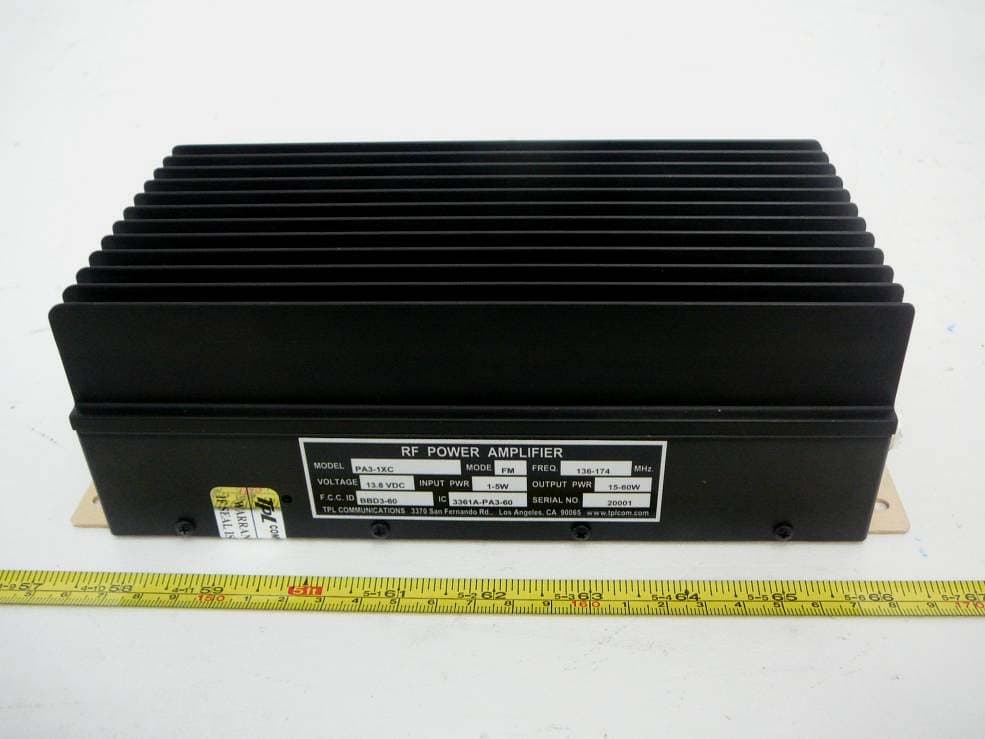
BBD3-60
Oct 09, 2012RF Power Amplifier
Equipment Class
AMP - Amplifier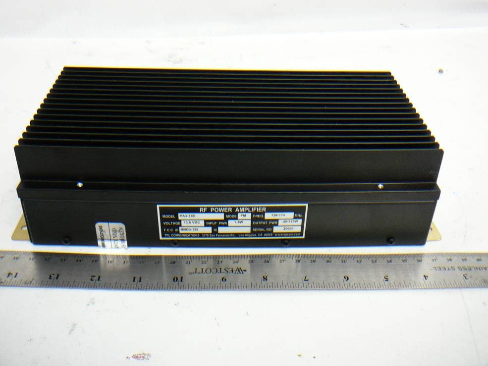
BBD3-125
Oct 01, 2012RF Power Amplifier
Equipment Class
AMP - Amplifier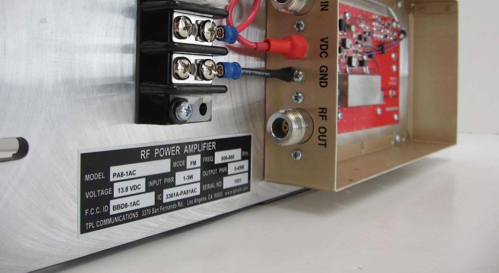
BBD8-1AC
Mar 31, 2010RF Power Amplifier
Equipment Class
AMP - Amplifier
BBD1-1AEL
Aug 13, 2007RF Power Amplifier
Equipment Class
AMP - Amplifier
BBDRC31FE
Jan 16, 2007RF Power Amplifier
Equipment Class
AMP - Amplifier