BBO0K29BT2K12BLUETOOTH ACCESSORY FOR CB
Cobra Electronics Corporation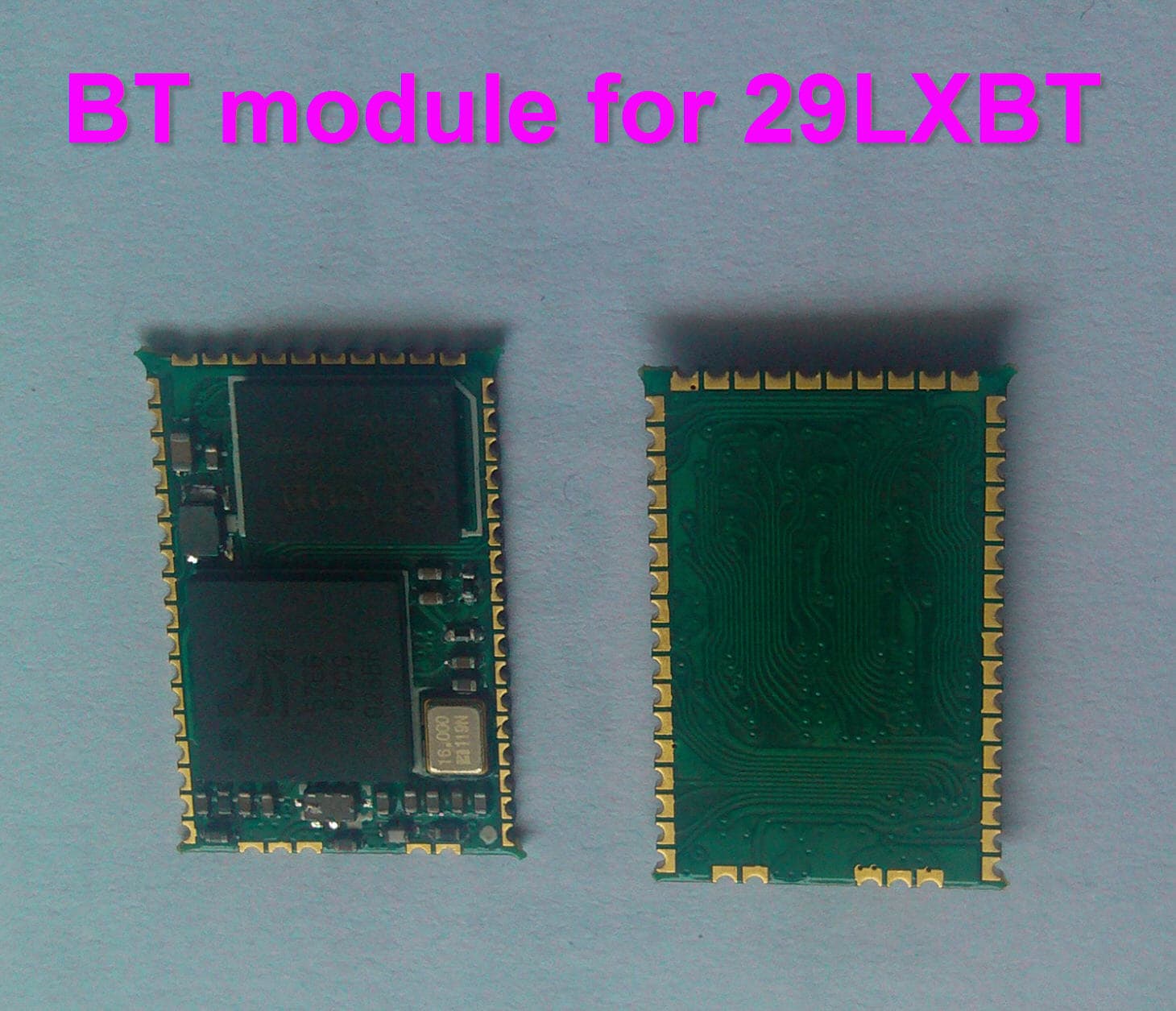
Click to zoom
Application Details
- Equipment Class
- DXX - Part 15 Low Power Communication Device Transmitter
- Date of Grant
- Apr 25, 2012
- Application Purpose
- Original Equipment
- Date of Application
- Apr 25, 2012
- Equipment Note
- BLUETOOTH ACCESSORY FOR CB
- Frequency Range
- 2402.00000000 - 2408.00000000
- Country
- United States
Documents & Files
Document Text
Text extracted from the exhibit documents filed with the FCC. Open a document above to read the original.
Users Manual
Contents Features ..................................................................................................................1 The CB Story ..........................................................................................................A1 FCC Regulations, FCC Warnings & Included Accessories Controls & Indicators .........................................................................................A2 Our Thanks to You ..............................................................................................A3 Customer Support Installation Location & Mounting/Connection ...........................................................2 Antennas CB Antenna & Marine Installation ............................................................6 Ignition Noise Interference.............................................................................7 Operating Your 29 LX BT Turning On Your CB ......................................................................................8 Setting Channel Selector.............................................................................9 Calibrate For SWR (Standing Wave Ratio).............................................10 To Receive .........................................................................................................12 Selecting a Channel ......................................................................................13 S-Meter ...............................................................................................................13 To Transmit.......................................................................................................14 Setting Dynamike ® ..............................................................................................15 Menu Mode ......................................................................................................16 Setting the Clock ............................................................................................17 Setting the Alarm .................................................................................................17 Setting the Count Down Timer .................................................................18 Key Tones Mode ...................................................................................................18 Radio Check Mode ...............................................................................................19 Setting Display Color Mode .......................................................................20 Setting Brightness Mode .............................................................................21 Setting Contrast Mode .......................................................................................21 Turn NightWatch Illumination On/Off ..........................................................21 Bluetooth Pairing .................................................................................................22 Turn Bluetooth Off .........................................................................................24 Weather Information ..........................................................................................25 Weather Channels .........................................................................................25 Weather Alert Mode ......................................................................................26 Setting Weather Alert Scan ........................................................................26 Setting Weather Auto Scan ........................................................................26 Software version/Factory Settings ..........................................................27 NB-ANL/Off (Noise Blanker/Automatic Noise Limiter Switch) ......28 Setting Delta Tune .........................................................................................28 RF Gain Control ...............................................................................................28 . Program Memory Channels .............................................................................29 Scan/Memory Scan ........................................................................................30 Scan Memory Channels ...............................................................................30 Scan CB Channels ..........................................................................................30 Dimmer Control ..............................................................................................30 Setting Squelch...............................................................................................31 S/RF Meter ........................................................................................................32 External Speaker .............................................................................................33 External Push-to-Talk Jack ..........................................................................33 External Mic Jack ............................................................................................33 . Home And Office Set-Up ...................................................................................34 Temporary Mobile Set-Up ..........................................................................35 How Your CB Can Serve You ..........................................................................36 A Few Rules You Should Know .................................................................36 Channel 9 Emergency Messages ..............................................................36 CB 10 Codes .....................................................................................................38 Frequency Ranges ..............................................................................................40 29 LX BT Specifications ....................................................................................41 Warranty Information .....................…
Text truncated - open the document above for the full version.
Users Manual
Operation Operation 17 16 Menu Mode Menu Mode Used to program special features. Menu/Enter knob is used to move cursor to desired feature to program. Rotate Menu/Enter knob clockwise to navigate menu levels. Press Menu/Enter knob to select feature to be programmed. Note Use Dim/Escape button to exit from any routine back to CB standby mode. Setting the Clock Setting the Clock Using the clock, alarm and countdown functions. To set the clock, press Menu/Enter knob and select Set Clock. 12:00 PM will appear in the display and the hours will flash. Rotate Menu/Enter knob clockwise to select desired hour and press to set. The minutes will then flash. Rotate Menu/Enter knob again to select desired minutes and press to set. Once the minutes are set, AM or PM will then flash. Rotate Menu/Enter knob again to select AM or PM and press to set or scroll down to EXIT and press to return to main menu. SWR/CAL NB/ANL VOLSQDYNAMIKERF GAINDELTA TUNE T BACK SWR CAL OFFMIN MINOFF MAX ESC MEM SCAN S/RF M E N U P U S H E N T E R SIG RF +30dB 1 1.5 2 3 CAL 3 5 7 9 SWR TX RX NB/ANL MEMWX ! ANL S/RF SWR CAL CH 9/ 19 CB / WX DIM SCAN SETTING BLUETOOTH EXIT SWR/CAL NB/ANL VOLSQDYNAMIKERF GAINDELTA TUNE T BACK SWR CAL OFFMIN MINOFF MAX ESC MEM SCAN S/RF M E N U P U S H E N T E R SIG RF +30dB 1 1.5 2 3 CAL 3 5 7 9 SWR TX RX NB/ANL MEMWX ! ANL S/RF SWR CAL CH 9/ 19 CB / W X / DIM SCAN PA SET CLOCK ALARM CLOCK SET COUNT DOWN SWR/CAL NB/ANL VOLSQDYNAMIKERF GAINDELTA TUNE T BACK SWR CAL OFFMIN MINOFF MAX ESC MEM SCAN S/RF M E N U P U S H E N T E R SIG RF +30dB 1 1.5 2 3 CAL 3 5 7 9 SWR TX RX NB/ANL MEMWX ! ANL S/RF SWR CAL CH 9/ 19 CB / W X / DIM SCAN PA KEY TONES WX ALERT WX ALERT SCAN Level 1: Level 2: SWR/CAL NB/ANL VOLSQDYNAMIKERF GAINDELTA TUNE T BACK SWR CAL OFFMIN MINOFF MAX ESC MEM SCAN S/RF M E N U P U S H E N T E R SIG RF +30dB 1 1.5 2 3 CAL 3 5 7 9 SWR TX RX NB/ANL MEMWX ! ANL S/RF SWR CAL CH 9/ 19 CB / W X / DIM SCAN PA WX AUTO SCAN DISPLAY COLOR BRIGHTNESS SWR/CAL NB/ANL VOLSQDYNAMIKERF GAINDELTA TUNE T BACK SWR CAL OFFMIN MINOFF MAX ESC MEM SCAN S/RF M E N U P U S H E N T E R SIG RF +30dB 1 1.5 2 3 CAL 3 5 7 9 SWR TX RX NB/ANL MEMWX ! ANL S/RF SWR CAL CH 9/ 19 CB / W X / DIM SCAN PA NW LIGHTING CONTRAST RADIO CHECK Level 3: Level 4: Level 5: Note Normal display will appear if clock has not yet been set. SWR/CAL NB/ANL VOLSQDYNAMIKERF GAINDELTA TUNE T BACK SWR CAL OFFMIN MINOFF MAX ESC MEM SCAN S/RF M E N U P U S H E N T E R SIG RF +30dB 1 1.5 2 3 CAL 3 5 7 9 SWR TX RX NB/ANL MEMWX ! ANL S/RF SWR CAL CH 9/ 19 CB / WX DIM SCAN SET CLOCK ALARM CLOCK SET COUNT DOWN SWR/CAL NB/ANL VOLSQDYNAMIKERF GAINDELTA TUNE T BACK SWR CAL OFFMIN MINOFF MAX ESC MEM SCAN S/RF M E N U P U S H E N T E R SIG RF +30dB 1 1.5 2 3 CAL 3 5 7 9 SWR TX RX NB/ANL MEMWX ! ANL S/RF SWR CAL CH 9/ 19 CB / WX DIM SCAN SET AM-PM 11:30 PM EXIT Note Use Dim/Escape button to exit from any routine back to CB standby mode. Setting the Alarm Setting the Alarm Your 29 LX can be utilized as an alarm clock. To set the alarm, press Menu/Enter knob and select Set Alarm. Rotate Menu/Enter knob clockwise to select Set Alarm Time. Follow instructions above for setting the alarm time and AM or PM. SWR/CAL NB/ANL VOLSQDYNAMIKERF GAINDELTA TUNE T BACK SWR CAL OFFMIN MINOFF MAX ESC MEM SCAN S/RF M E N U P U S H E N T E R SIG RF +30dB 1 1.5 2 3 CAL 3 5 7 9 SWR TX RX NB/ANL MEMWX ! ANL S/RF SWR CAL CH 9/ 19 CB / WX DIM SCAN SET CLOCK ALARM CLOCK SET COUNT DOWN Note The radio should be connected to a constant 12V source to maintain the time when the radio is turned off. 29LXBT_MANL.indd 16-172/27/12 11:14 AM Setting the Count Down Timer To set the count down timer, press Menu/Enter knob and select Set Count Down. Follow instructions in Setting the Clock section (page 17) to set count down hour and minutes. Once desired count down time is selected, press Menu/Enter knob again to set and return to the standby menu. Radio Check Mode Radio Check Mode Allows testing of important radio functions. Test 1- Battery Level: Confirms that battery voltage level is between 10.8 V to 15.8 V. If in that range, it is “PASS”. Outside of that range, either FAIL LOW” or “FAIL HIGH” will be displayed. Press Menu/Enter knob to advance to next test. Note Press Dim/Escape button to return to CB standby mode. If 10 seconds pass or if Enter button pressed, unit goes to 2nd test. Test 2- RF Power Output: Confirms 3.3 to 4 Watt output level. Once Push-to-Talk button is pressed, Pass or Fail will be displayed if level is outside limits. Note Press Dim/Escape button to return to CB standby mode. If 10 seconds pass or if Enter button pressed, go to 3rd test. Note Press Push-To-Talk within 10 seconds or unit will go to the next test. SWR/CAL NB/ANL VOLSQDYNAMIKERF GAINDELTA TUNE T BACK SWR CAL OFFMIN MINOFF MAX ESC MEM SCAN S/RF M E N U P U S H E N T E R SIG RF +30dB 1 1.5 2 3 CAL 3 5 7 9 SWR TX RX NB/ANL MEMWX ! ANL S/RF SWR CAL CH 9/ 19 CB / W X / DIM SCAN PA RF POWER OUTPUT PASS SWR/CAL NB/ANL VOLSQDYNAMIKERF GAINDELTA TUNE T BACK SWR CAL OFFMIN MINOFF MAX ESC MEM SCAN S/RF M E N U P U S H E N T E R SIG RF +30dB 1 1.5 2 3 CAL 3 5 7 9 SWR TX RX NB/ANL MEMWX ! ANL S/RF SWR CAL CH 9/ 19 CB / W X / DIM SCAN PA RF POWER OUTPUT FAIL Note Press Dim/Escape button to return to CB standby mode. If 10 seconds pass or if Enter button pressed, testing is complete. Unit will return to CB Standby mode. Test 3- Antenna Mismatch Warning: Press Push-to-Talk button to check antenna/radio for proper matching. SWR/CAL NB/ANL VOLSQDYNAMIKERF GAINDELTA TUNE T BACK SWR CAL OFFMIN MINOFF MAX ESC MEM SCAN S/RF M E N U P U S H E N T E R SIG RF +30dB 1 1.5 2 3 CAL 3 5 7 9 SWR TX RX NB/ANL MEMWX ! ANL S/RF SWR CAL CH 9/ 19 CB / W X / DIM SCAN PA ANTENNA PASS SWR/CAL NB/ANL VOLSQDYNAMIKERF GAINDELTA TUNE T BACK SWR CAL OFFMIN MINOFF MAX ESC MEM SCAN S/RF M E N U P U S H E N T E R SIG RF +30dB 1 1.5 2 3 CAL 3 5 7 9 SWR TX RX NB/ANL MEMWX ! ANL S/RF SWR CAL CH 9/ 19 CB / W X / DIM SCAN PA ANTENNA FAIL 1 2 3 1 2 3 1 2 3 Op…
Text truncated - open the document above for the full version.
Users Manual
Weather Information Note If you wish to receive a listing of NOAA ‘Weather Radio Transmitter locations, contact your nearest National Weather Service Office or write to: National Weather Service (Attn: W/OM11) NOAA Silver Springs, MD 20910. For ideal weather reception use a dual band antenna (center load/baseload). Weather Alert What You Should Know About Weather If threatening weather is nearby, the National Weather Service may broadcast a 10 second alert tone. This tone will be heard through the CB, even if the CB/WX Control is in the CB mode or the unit is turned off. This enables you to monitor CB frequencies and still be warned by the National Weather Service Emergency Alert. When you hear the alert, press the CB/WX button in the WX mode. You will then be able to hear the Weather Warning Broadcast. Your 29 LX BT has a special auto squelch circuit for weather transmission which disables your squelch control. Weather Channels Weather Alert Scan The unit will continually scan all 10 WX channels for 1050 Hz tone. If the tone is detected the unit will activate WX mode on the channel with the tone. Default state is Off. Go to Menu mode to choose On/Off (see page 22): What is Weather Radio? NOAA Weather Radio (NWR) is a service of the National Oceanic and Atmospheric Administration (NOAA), of the U.S. Department of Commerce. 380 NWR sta- tions are in operation by the U.S. Government in addition to several NWR stations that are maintained by private interest groups. The capability is to sup- plement warnings by sirens and by commercial radio and televi- sion. The 10 National Weather Channels provide full cover- age to keep you informed of weather conditions, 24 hours a day, 7 days a week. Weather Auto Scan If active while in CB mode, will determine if the present WX channel is active. If the present WX channel is not active, will search for the strongest WX channel and auto change to that channel. Default is off. Go to Menu mode to choose on/off (see page 22). SWR/CAL NB/ANL VOLSQDYNAMIKERF GAINDELTA TUNE T BACK SWR CAL OFFMIN MINOFF MAX ESC MEM SCAN S/RF M E N U P U S H E N T E R SIG RF +30dB 1 1.5 2 3 CAL 3 5 7 9 SWR TX WX ! S/RF CH 9/ 19 CB / WX DIM SCAN 163.275 2524 Operation Operation Bluetooth ® continued To Place a call on Hold The display will show: Press Enter knob. This puts the call on hold allowing CB communication. To Return to Phone Call The display will show: Press Menu Enter knob again. SWR/CAL NB/ANL VOLSQDYNAMIKERF GAINDELTA TUNE T BACK SWR CAL OFFMIN MINOFF MAX ESC MEM SCAN S/RF M E N U P U S H E N T E R SIG RF +30dB 1 1.5 2 3 CAL 3 5 7 9 SWR TX RX NB/ANL MEMWX ! ANL S/RF SWR CAL CH 9/ 19 CB / WX DIM SCAN GO TO CB PRESS ENTER TO SWR/CAL NB/ANL VOLSQDYNAMIKERF GAINDELTA TUNE T BACK SWR CAL OFFMIN MINOFF MAX ESC MEM SCAN S/RF M E N U P U S H E N T E R SIG RF +30dB 1 1.5 2 3 CAL 3 5 7 9 SWR TX RX NB/ANL MEMWX ! ANL S/RF SWR CAL CH 9/ 19 CB / WX DIM SCAN RETURN TO CALL PRESS ENTER TO Note If, while on hold the call is dropped, you will hear a sound beep and the CB radio will return to standby. Allows for voice Caller ID, e-mails and text messages to be read through the CB radio. Note A third party app download is required in order for this feature to be functional. To Turn Bluetooth Off on the Radio: Press Menu/Enter and select Bluetooth: Press Menu/Enter again and select Bluetooth: Press and select Off. SWR/CAL NB/ANL VOLSQDYNAMIKERF GAINDELTA TUNE T BACK SWR CAL OFFMIN MINOFF MAX ESC MEM SCAN S/RF M E N U P U S H E N T E R SIG RF +30dB 1 1.5 2 3 CAL 3 5 7 9 SWR TX RX NB/ANL MEMWX ! ANL S/RF SWR CAL CH 9/ 19 CB / WX DIM SCAN EXIT BLUETOOTH SWR/CAL NB/ANL VOLSQDYNAMIKERF GAINDELTA TUNE T BACK SWR CAL OFFMIN MINOFF MAX ESC MEM SCAN S/RF M E N U P U S H E N T E R SIG RF +30dB 1 1.5 2 3 CAL 3 5 7 9 SWR TX RX NB/ANL MEMWX ! ANL S/RF SWR CAL CH 9/ 19 CB / WX DIM SCAN OFF BLUETOOTH ON EXIT A2DP Audio Streaming 29LXBT_MANL.indd 24-252/27/12 11:14 AM Operation Operation 2726 Setting Weather Auto Scan Press Menu/Enter knob and rotate clockwise to WX Auto Scan. Press Menu/Enter knob to select On/Off. Press Menu/Enter knob to select On/Off and exit to main menu. SWR/CAL NB/ANL VOLSQDYNAMIKERF GAINDELTA TUNE T BACK SWR CAL OFFMIN MINOFF MAX ESC MEM SCAN S/RF M E N U P U S H E N T E R SIG RF +30dB 1 1.5 2 3 CAL 3 5 7 9 SWR TX RX NB/ANL MEM ANL S/RF SWR CAL CH 9/ 19 CB / WX D IM SCAN ON OFF AUTO SCN IS OFF Setting Weather Auto Scan Setting Weather Alert Scan Press Menu/Enter knob and rotate clockwise to WX Alert Scan. Press Menu/Enter knob to select On/Off. Press Menu/Enter knob to select On/Off and exit to main menu. SWR/CAL NB/ANL VOLSQDYNAMIKERF GAINDELTA TUNE T BACK SWR CAL OFFMIN MINOFF MAX ESC MEM SCAN S/RF M E N U P U S H E N T E R SIG RF +30dB 1 1.5 2 3 CAL 3 5 7 9 SWR TX RX NB/ANL MEM ANL S/RF SWR CAL CH 9/ 19 CB / W X D IM SCAN WX SCN IS OFF ON OFF Weather Alert Mode Setting Weather Alert Mode Turns WX Alert On/Off. Default is Off. Press Menu/Enter knob to select Set WX Alert. If Weather is On, WX Alert Icon will be displayed. Press Menu/Enter knob to select On/Off and exit to main menu. SWR/CAL NB/ANL VOLSQDYNAMIKERF GAINDELTA TUNE T BACK SWR CAL OFFMIN MINOFF MAX ESC MEM SCAN S/RF M E N U P U S H E N T E R SIG RF +30dB 1 1.5 2 3 CAL 3 5 7 9 SWR TX RX NB/ANL MEM ANL S/RF SWR CAL CH 9/ 19 CB / WX D IM SCAN WX ALERT IS OFF ON OFF WX ! Setting Weather Alert Scan Note Press Dim/Escape button to return to CB mode. Software Version/Factory Settings Software Version/Factory Settings Displays current software version and returns unit to original factory settings. To view software version, rotate Menu/Enter knob clockwise to select Settings then Software Version. To restore default settings, Press Menu/Enter knob again. Rotate Menu/Enter knob clockwise to select Settings then Go To Default. Press Menu/Enter knob to restore default settings. Choose NO to maintain present setting with no change. SWR/CAL NB/ANL VOLSQDYNAMIKERF GAINDELTA TUNE T BACK SWR CAL OFFMIN MINOFF MAX ESC MEM SCAN S/R…
Text truncated - open the document above for the full version.
Users Manual
Operation Operation 33 S/RF Meter External Speaker S/RF Meter This meter swings proportionately to the RF output (outgoing signal) while transmitting. External Speaker The external speaker jack is used for remote receiver monitoring. The S/RF-SWR-CAL button must be in the S/RF mode. 1 Note The external speaker should have 8-ohm impedance and be rated to handle at least 4.0 watts. When the external speaker is plugged in, the inter- nal speaker is automatically disconnected. Note Cobra external speakers are rated at 10 watts. Note USB Output: This jack is used to charge or power most 5 Volt USB devices. Connect an external speaker to the external speaker jack on the rear panel. 32 To achieve the Desired Squelch Setting (DSS), turn the Squelch control counterclockwise until you hear noise. Now turn the control clockwise just until the noise stops. This is the DSS setting. 3 NOISE WEAK SIGNALS MEDIUM SIGNALS STRONG SIGNALS GA TE Gate set to Desired Squelch Setting (DSS) Setting Squelch Continued ANT BO3K229LTD BRA IN CHINA EXT MIC EXT. PTT EXT.SP. +POWER– USB R R ANT BO3K229LTD BRA IN CHINA EXT MIC EXT. PTT EXT.SP. +POWER– USB External Push-to-Talk Jack The external push-to-talk jack is used for remote transmit function with optional PTT (see accessory page 44). Connect an external push-to-talk to the external push-to-talk jack on the rear panel. ANT BO3K229LTD BRA IN CHINA EXT MIC EXT. PTT EXT.SP. +POWER– USB External Microphone Jack The external microphone jack is used for connecting external microphone for CB and phone audio function. Connect the external microphone (included) to the external microphone jack on the rear panel. ANT BO3K229LTD BRA IN CHINA EXT MIC EXT. PTT EXT.SP. +POWER– USB 29LXBT_MANL.indd 32-332/27/12 11:14 AM Temporary Mobile Set-Up Home And Office Set-Up 3534 Base Station Operation (From 120V AC House Current) Temporary Mobile Set-Up Temporary Mobile Operation For temporary mobile operation you may want to purchase an optional cigarette lighter adapter from your COBRA dealer. This adapter and a magnetic mount antenna allow you to quickly “install” your transceiver for temporary use. ANT FCC ID:BBO3K229LTD COBRA MADE IN CHINA EXT MIC EXT. PTT EXT.SP. +POWER– USB Base Station Operation (From 120V AC House Current) To operate your transceiver from home or office you will need a 13.2 volt DC Power Pack rated at a minimum of 2 amps, and a properly installed base station antenna. Warning! Do not attempt to operate this transceiver by connecting it directly to 120V AC. Note For further information call Cobra Customer Service 1.773.889.3087. 1 Connect properly installed and matched base station antenna. Simply connect the red (+) and black (-) leads of the transceiver to the corresponding terminals of the power pack. Plug power cable into back of unit marked “Power”. Be sure to observe polarity markings. 2 3 ANT FCC ID:BBO3K229LTD COBRA MADE IN CHINA EXT MIC EXT. PTT EXT.SP. +POWER– USB +— 29LXBT_MANL.indd 34-352/27/12 11:14 AM How Your CB Can Serve You 3736 How Your CB Can Serve You The FCC gives these examples of permitted and prohibited messages for channel 9. These are only guidelines and not all-inclusive: Permitted Example Message Yes “Tornado sighted six miles north of town.” No “Post number 10. No tornado sighted.” Yes “Out of gas on I-95 at mile marker 211.” No “Out of gas in my driveway.” Yes “Four car accident on I-94 at Exit 11. Send police and ambulance.” No “Traffic moving smoothly on I-94.” Yes “Weather Bureau has issued thunderstorm warning. Bring sailboat into port.” No “Attention motorists. Weather Bureau advises snow tomorrow will accumulate 4 to 6 inches.” Yes “Fire in building at 539 Main, Evanston.” No “Halloween patrol number 3. All quiet.” 1. Set to channel 9 for emergencies Be sure antenna is properly connected. 2. CB Distress Data When transmitting an emergency, you should request a “REACT BASE” and provide the CB distress data (called CLIP): C all Sign Identify yourself. L ocation Be exact. I njuries Number. Type. Trapped? P roblem Give details and help needed. Transmit CLIP repeatedly so any monitor can assist. Channel 9 Emergency Messages Note If no response on channel 9, try channels 19 or 14. • Warn of traffic problems • Provide weather and road data • Provide help in event of an emergency • Provide direct contact with home or office • Assist police by reporting erratic drivers • Get “local information” to find destination • Communicate with family and friends • Suggest spots to eat and sleep • Keep you alert while traveling A Few Rules You Should Know A. Conversations cannot last more than 5 minutes with another station. A one minute break is required to let others use the channel. B. You cannot blast others off the air by use of illegally amplified transmitters or illegally high antennas. C. You cannot use CB to promote illegal activities. D. Profanity is not allowed. E. You may not transmit music with a CB. F. Selling of merchandise and/or services is prohibited. A Few Rules You Should Know 29LXBT_MANL.indd 36-372/27/12 11:14 AM How Your CB Can Serve You 3938 Code Meaning 10-29 Time is up for contact 10-30 Does not conform to FCC rules 10-33 Emergency traffic 10-34 Trouble at this station 10-35 Confidential information 10-36 Correct time is 10-37 Wrecker needed at 10-38 Ambulance needed 10-39 Message delivered 10-41 Turn to channel 10-42 Traffic accident at 10-43 Traffic tie up at 10-44 Have a message for 10-45 All units within range please report 10-50 Break channel 10-60 What is next message number? 10-62 Unable to copy. Use phone 10-63 Net directed to 10-64 Net clear 10-65 Awaiting your next message/assignment 10-67 All units comply 10-70 Fire at 10-71 Proceed, transmission in sequence 10-77 Negative contact 10-81 Reserve hotel room for 10-82 Reserve room for 10-85 My address is 10-91 Talk closer to mic 10-93 Check my frequency on this channel 10-94 Give me a long count 10-99 Mission completed, all units secure 10-200 Police needed at CB 1…
Text truncated - open the document above for the full version.
Parts List/Tune Up Info
Item DescriptionQty Reqd. 29LBTXXXUSBKXX 29 LX BT CB RADIO WITH BT & USB HG-76N MIC WHITE UNIT (ALL)1 HG-76NC MIC WHITE CASING (ALL)1 HG-76NCXXX MIC WHITE CASING COMMON1 GEM-M8415 MIC METAL GRILL (STEEL-NET)1 GEM-OT8415 NOISE CACELING MEDALLION (AL+RUBBER) 1 GEM-OT8416 MIC CUSHION (EVA)1 GEM-OT8417 BT MIC NET FILM (FELT)1 GEM-OT8418 BT MIC SLEEVE (RUBBER)1 GEM-OT8420-01 MIC CUSHION ON (HUI LI JIAO) 1 GEM-OT9005A PVC SLEEVE0.03 GEOE-OT041 FIBRE SLEEVING DIA 1.5mm 0.008 GEPC-472-A PCB FOR HGM73 S.S1 GESP-016 MIC DYNAMIC0 GESP-016-C MIC DYNAMIC OS40500H16 FADA0 GESP-016-C MIC DYNAMIC OS40500H16 FADA0 GESP-016-A MIC DYNAMIC A40-001 ASAHI1 GESW-018-1 SWITCH PUSH 2P2T PS-22I01-RP 1 KEJ-513 MIC PLUG 6PIN N-16-6P QIINGXING 0 KEJ-513-A MIC PLUG 6PIN FD-M16-6A FADA 1 KEJW-SA24BK STRAND WIRE UL1007 #24 BLACK 0.19 KEM-OT5215 PVC TAPE 124090.2 KEM-P5053A-01 MIC BRACKET1 KEM-P5056A FRONT CABINET OF C29BT MIC ABS 1 KEM-P5057 MIC BACK CABINET (ABS)1 KEM-P5058 PTT KNOB (ABS)1 KEM-P5059 BT BUTTON (ABS)1 KEM-P5059-Z BT BUTTON PRINTING1 KEM-P5059-01 BT BUTTON WITHOUT PRINTING1 KEM-P7107C HANDING KNOB1 KEM-TS2606W1Z TAPPING SCREW(CUTTING) 2.6X6 1 KEM-TS2608B1N TAPPING SCREW B/HD T2.6x85 KEM-TS3010P1B TAPPING SCREW P/HD T3X101 KEOE-OT042 FIBRE SLEEVING DIA 2MM0.095 KEPC-1082-A PCB 34*14*1.6MM SS 94V-01 KESP-041-C MIC ELEC CI0340 KESP-041-D1 MIC KSJ9765 ECM CHOFEXT1 KESW-015 SWITCH TACT EVQ-JAC-04M1 KETC-160-A CURL CORD 6 CORES 3.26M C&CC 22030004 0 KETC-160 CURL CORD 6 CORES 3.26M P0711125 1 29LBTB MAIN UNIT ALL1 29LBTBC MAIN CASING ALL1 29LBTBCXXX MAIN CASING COMMON1 GEJW-FC5000 FLAT CABLE 8 PINS L=46MM PITCH 2.5MM 1 GEM-M0702-01 MOUNTING PLATE SCREW2 Bill of Material for CB29LX BT Page: 1 / 13 GEM-M8403 INSERT 1 FOR INSERT KNOB2 GEM-M8405A BOTTOM COVER1 GEM-M8405A-10 BOTTOM COVER NEW TEXTURE0 GEM-M8413 TOP COVER WITH COBRA LOGO C29BT (SECC+PVC) 1 GEM-M8413-10TOP COVER WITH COBRA LOGO C29BT (SECC+PVC) NEW TEXTUR0 GEM-NF0553040Z FLANGE NUT M3.04 GEM-OT0704 RUBBER RING 15 OD x 7 ID x 2 THK 2 GEOE-OT273 COAXIAL CABLE 1.5D-QEV. 200MM 1 GER-D503B503A-6 VR DUAL SHAFT B50KA50K RD12DSF-10B2-35FG-073-S018 ALP1 GER-RD12DSF-7VR DUAL SHAFT B10K B500X2 RD12DSF-10B2-35FG-118-S0181 GER-102JBB RES. C-FILM 1/8W 5% S 1K1 GER-102P11-6 POT 1KB RV16AF-10-28K-B1K RF GAIN 1 GER-203P07-6 POT 20KB RV16AF-10-28K-B20K-OC DELTA TURN 1 GER-502P10-6 POT 5KA RV16AF-10-28K-A5K DYNAMIKE 1 GESP-056-C SPEAKER 8OHM 5.5W 102FD0H0-8P-3F21 1 GESP-056-B SPEAKER 8OHM 5.5W DAIN0 GESP-056 SPEAKER 8 OHM 5.5W0 KEJ-525-A MIC SOCKET 6PIN FD-M16-6G1 FADA 1 KEJ-525 MIC SOCKET 6PIN N-16-6R0 KEJC-001 FOR J301 5PIN PIN WIRE UL1007 #24 ECONN 1 KEJC-002 FOR J302 5PIN PIN WIRE UL1007 #24 ECONN 1 KEJC-003 FOR J303 5PIN PIN WIRE UL1007 #24 ECONN 1 KEJC-004 FOR J304 5PIN PIN WIRE UL1007 #24 ECONN 1 KEJC-005 FOR J305 5PIN PIN WIRE UL1007 #24 ECONN 1 KEJC-006 FOR J306 7PIN PIN WIRE UL1007 #24 ECONN 1 KEJC-007 FOR J307 4PIN PIN WIRE UL1007 #24 ECONN 1 KEJC-008 FOR J308 4PIN PIN WIRE UL1007 #24 ECONN 1 KEJW-SA24AE STRAND WIRE UL1007 #24 ORANGE 0.31 KEJW-SA24BK STRAND WIRE UL1007 #24 BLACK 0.42 KEJW-SA24BL STRAND WIRE UL1007 #24 BLUE 0.96 KEJW-SA24BN STRAND WIRE UL1007 #24 BROWN 0.21 KEJW-SA24GR STRAND WIRE UL1007 #24 GREEN 0.66 KEJW-SA24RD STRAND WIRE UL1007 #24 RED 0.49 KEJW-SA24WE STRAND WIRE UL1007 #24 WHITE 0.58 KEJW-SA24YW STRAND WIRE UL1007 #24 YELLOW 0.96 KEJW-TA24BK TINNED WIRE UL1007 #24 BLACK 0.1 KEJW-TA24BL TINNED WIRE UL1007 #24 BLUE 0.125 KEJW-TA24RD TINNED WIRE UL1007 #24 RED 0.175 KEJW-TA24WE TINNED WIRE UL1007 #24 WHITE 0.125 KEJW-TA24YW TINNED WIRE UL1007 #24 YELLOW 0.125 KEM-MS2506P2N M2.5MM*P0.45Metal screw L=6mm 6 KEM-MS2512P2N M2.5MM*P0.45Metal screw2 KEM-MS3006C2N SCREW-MACHINE F/H M3X6MM4 KEM-MS3006P2N SCREW-MACHINE P/H M3X6MM2 KEM-M33602A-02 Radio front pcb fix metal plat 1 KEM-M33604 LEFT FUNCTION 2 KEYS METAL DOME 1 KEM-M33605 RIGHT FUNCTION 4 KEYS METAL DOME 1 Page: 2 / 13 KEM-OT0706 FELT STRIP 75X10MM2 KEM-OT33603-01 CB RADIO LCD CUSHION1 KEM-OT33604-03 0.1MM WHITE RIGHT PET(28.1X25) 1 KEM-OT33605-03 0.1mm WHITE LEFT PET(46.7x25.1MM) 1 KEM-OT33606-01 0.1MM PET TOP PROTECTMEMBRANE(18x10mm) 2 KEM-OT33610 3M DOUBLE GLUE FOR BACKLIGHT 2 KEM-OT33611 PET FOR PROTECT TOP PCB1 KEM-OT33612A-01 3M for fixing radio face plate(3m9446) 1 KEM-OT33618 3M for fixing little pcb plate12340.25mm 1 KEM-OT33619 3M for fixing arc pcb plate 274.50.25mm 1 KEM-OT33622 FACE PLATE FOR RADIO PC FILM T0.3MM 1 KEM-OT4955 FELT 65X10X092 KEM-OT5215 PVC TAPE 124090.06 KEM-OT8413 INSULATION FILM1 KEM-OT8415 INSULATION FILM 20180.1mm6 KEM-P33601A-01 FRONT CABINET OF 29LBT ABS WITH Cr-plating 1 KEM-P33602-01 CB Radio front cabinet wall1 KEM-P33603-01 CB Radio left function button 1 KEM-P33604-01 CB Radio Tune/select knob1 KEM-P33605-01 CB Radio control knob3 KEM-P33606B-01 Bronzing CB Radio Black Small Connectric KnobABS(PA712 KEM-P33607-01 CB Radio large concentric knob 2 KEM-P33617A-01 CB Radio large concentric knob 0 KEM-P33608-01 CB Radio right function button 1 KEM-P33618-01 CB Radio right function button 0 KEM-P33619-01 CB RADIO LENS1 KEM-TS3006B5B TAPTITE SCREW B/H S M3x612 KEOE-OT182 CABLE TIE TSL-102M 2.5X10²MM 8 KEPC-1142-A PCB 20.8X17X1.6MM 1LAYER FR4 1 KESW-140-6 ENCODER RE111F-41B3-32K-20P-6 ALPHA 1 29LBTB1 MAIN PCB ALL1 29LBTB1XXX MAIN PCB COMMON1 GCD-1SV215 DIODE VARICAP 1SV2151 GCD-214 DIODE VARACTOR 1SV2141 GEC-E106ERMKS CAP. ELECT. 16V M% 10UF1 GEC-E225HRMU CAP. ELECT. 50V M% 2.2UF2 GEC-E227DRMU CAP. ELECT. 10V M% 220UF1 GEC-E336ERMU CAP. ELECT. 16V M% 33UF1 GEC-E474HRMU CAP. ELECT. 50V M% 0.47UF1 GEC-E475FRMU CAP. ELECT. 25V M% 4.7UF2 GEC-E476DRMU CAP. ELECT. 10V M% 47UF2 GEC-MY102IRKA CAP. MYLAR 100V K% 0.001UF2 GEC-MY103IRKA CAP. MYLAR 100V K% 0.01UF1 GEC-MY104IRKA CAP. MYLAR 100V K% 0.1UF1 GEC-MY222IRKA CAP. MYLAR 100V 10% 0.0022UF 1 GEC-MY223IRKA CAP. MYLAR 100V K% 0.022UF1 GEC-MY333IRKA CAP. MYLAR 100V K% 0.033UF1 Page: 3 / 13 GEC-MY393IRKA CAP. MYLAR 100V K% 0.039UF7 GEC-MY473IRKA CAP. MYLAR 100V K% 0.047UF1 GEC-MY682IRKA CAP. MYLAR 100V K% 0.0068UF2 G…
Text truncated - open the document above for the full version.
Contact Information
Applicant
Chris de Waal(Senior Project Engineer)
Test Firm
Timco Engineering, Inc.Bruno Clavier
Technical Specifications
| # | Rule Parts | Frequency Range | Power Output |
|---|---|---|---|
| 1 | 15C | 2.40 GHz - 2.41 GHz | 2.50 mW |
Other Applications from Cobra Electronics Corporation
BBOCHEM01
Jul 21, 2026Radar detector
Equipment Class
CRD - Part 15 Radar DetectorBBOPERF600
Jul 13, 2026PERFORMA 600 RADIO DIGITAL BULK, US/COBRA PERFORMA 600 DIGITAL SINGLE PACK, US/COBRA PERFORMA 600 DIGITAL SIX PACK, US/COBRA PERFORMA 600 DIGITAL RADIO, US
Equipment Class
TNF - Licensed Non-Broadcast Transmitter Held to Face
BBOBB650
May 01, 2026VHF Marine Radio Transceiver
Equipment Class
TNF - Licensed Non-Broadcast Transmitter Held to FaceBBOLESS01
Apr 14, 2026Radar detector with Bluetooth
Equipment Class
DTS - Digital Transmission System
BBOCBPT01
Feb 14, 2023Wireless PTT
Equipment Class
DTS - Digital Transmission System