BBO2104BFRS/GMRS TRANSCEIVER
Cobra Electronics Corporation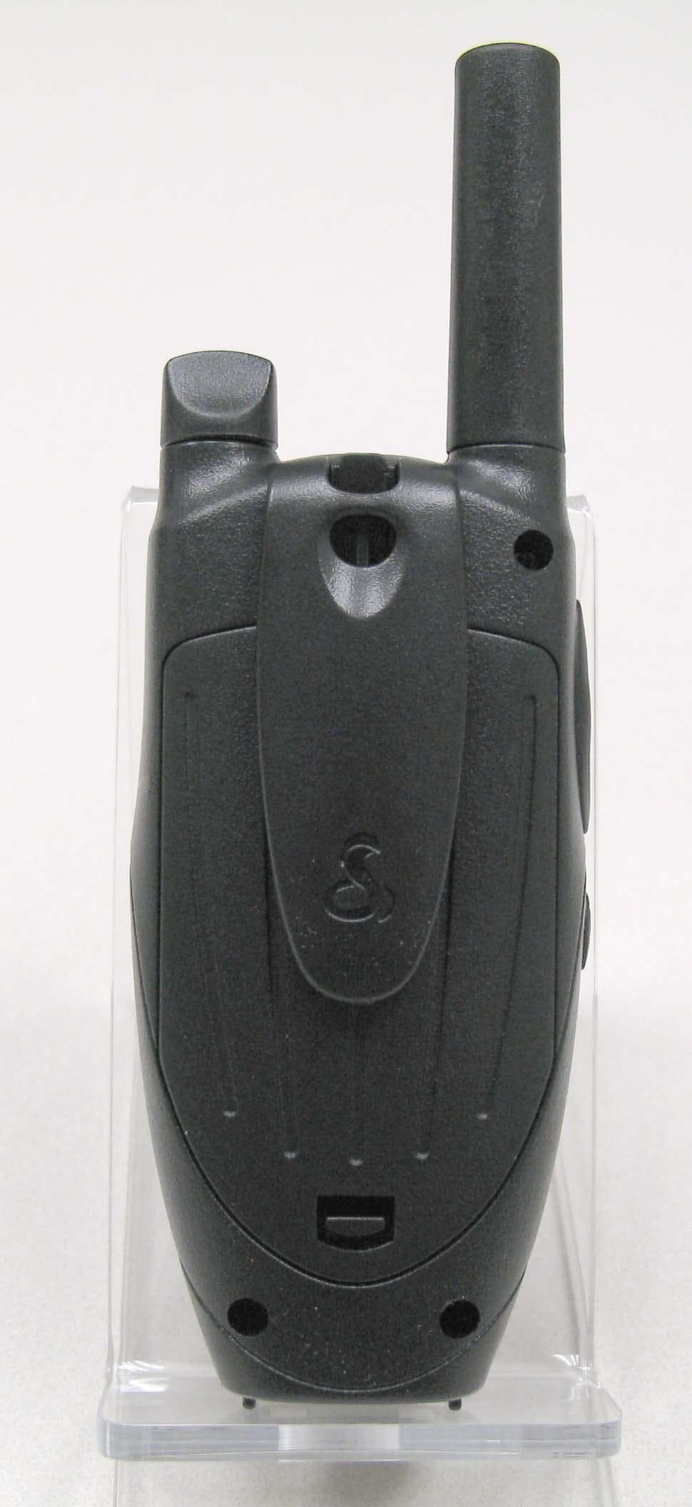
Click to zoom
Application Details
- Equipment Class
- FRF - Part 95 Family Radio Face Held Transmitter
- Date of Grant
- Apr 01, 2010
- Application Purpose
- Original Equipment
- Date of Application
- Mar 23, 2010
- Equipment Note
- FRS/GMRS TRANSCEIVER
- Frequency Range
- 462.56250000 - 467.71250000
- Country
- United States
Documents & Files
Document Text
Text extracted from the exhibit documents filed with the FCC. Open a document above to read the original.
Users Manual
Nothing Comes Close to a Cobra ® English For more information or to order any of our products, please visit our website: www.cobra.com A1 Making Life Easier and Safer Owner’s Manual Nothing Comes Close to a Cobra ® TWO-WAY RADIO MODEL CXT425 Printed in China Part No. 480-575-P Version A Introduction Staying in touch with your family and friends is convenient and easy when using your microTALK ® radio. Some of the many uses you will discover include: Communicating with others while hiking, biking and working; keeping track of family and friends at a crowded public event; checking with travel companions in another car; talking with neighbors; arranging meeting spots with others while shopping at the mall. Secure your microTALK radio while on the go. Carrying your microTALK radio with you is easy when using the belt clip. The belt clip easily attaches to your belt, purse or backpack. For Assistance in the U.S.A. In this user’s manual, you should find all the information you need to operate your microTALK radio. If you require further assistance after reading this manual, Cobra Electronics offers the following customer assistance services: Automated Help Desk English only. 24 hours a day, seven (7) days a week 773-889-3087 (phone). Customer Assistance Operators English and Spanish. 8:00 a.m. to 5:30 773-889-3087 (phone). Questions English and Spanish. Faxes can be received at 773-622-2269 (fax). Technical Assistance English only. www.cobra.com (on-line: Frequently Asked Questions). English and Spanish. productinfo @cobra.com (e-mail). For Assistance Outside the U.S.A. Contact Your Local Dealer Belt Clip Customer Assistance © 2009 Cobra Electronics Corporation™ 6500 West Cortland Street Chicago, Illinois 60707 USA www.cobra.com A3 Product Features A2 Product Features Introduction Introduction Backlit LCD Display • 22 Channels Seven shared with FRS/GMRS, seven FRS only, eight GMRS only • 121 Privacy Codes (38 CTCSS codes/ 83 DCS codes) • 10 Channel NOAA All Hazards Radio • Hands-Free Operation (VOX) • 10 Channel Memory • Signal Strength Meter • Scan Channels, privacy codes, memory • Selectable Hi•Low Power In GMRS • Backlit LCD Display • Button Lock • Call Alert 10 selectable tones • Speaker/ Microphone/ Charge Jack • Roger Beep Selectable on/off • Battery/Power Saver • Keystroke Tones Selectable on/off • Auto Squelch • Maximum Range Extender • Belt Clip 1 2 3 8 4 5 7 6 10 11 12 9 1. Antenna 2. External Speaker/ Microphone/Charge Jack 3. On/Off Volume Knob 4. Backlit LCD Display 5. Channel Up Button 6. Channel Down Button 7. Mode/Lock Button 8. Speaker/Microphone 9. Call Button 10. Light/Max Range Button 11. Talk Button 12. Enter/Hi-Low Power Button 13. Wrist Strap Connector 14. Belt Clip 15. Battery Compartment 16. Battery Door Latch 1 2 3 4 6 9 10 12 14 15 16 11 13 5 8 13 14 15 16 7 Important FCC Licensing Information This radio operates on General Mobile Radio Ser- vice (GMRS) frequencies which require a Federal Communications Commission (FCC) license. See page 22 for licensing and other related information. Maximum range may vary and is based on unobstructed line-of-sight communication under ideal conditions. 1. Signal Strength Meter Icon 2. Lock Icon 3. Keystroke Tones Icon 4. Roger Beep Icon 5. VOX Icon 6. NOAA All Hazards Radio Icon 7. DCS/CTCSS Icons 8. Scan Icon 9. Memory Icon 10. Memory Location Number 11. Privacy Code Numbers 12. Hi-Low Power Icons 13. Receive/Transmit Icons 14. Battery Low Indicator 15. Power Saver Icon 16. Channel Numbers Safety and Trademark Acknowledgement Safety Safety Information for microTALK ® Radios • Your wireless handheld portable transceiver contains a low power transmitter. When the talk button is pushed, it sends out radio frequency (RF) signals. The device is authorized to operate at a duty factor not to exceed 50%. In August 1996, the Federal Communications Commission (FCC) adopted RF exposure guidelines with safety levels for handheld wireless devices. Important: FCC RF Exposure Requirements: For body-worn operation, this radio has been tested and meets the FCC RF exposure guidelines when used with Cobra accessories supplied or designated for this product. Use of other accessories may not ensure compliance with FCC RF exposure guidelines. Use only the supplied antenna. Unauthorized antennas, modifications, or attachments could damage the transmitter and may violate FCC regulations. Normal Position: Hold the transmitter approximately five cm (two inches) from your face and speak in a normal voice, with the antenna pointed up and away. Trademark Acknowledgement • Cobra ® , microTALK ® , Nothing Comes Close to a Cobra ® , VibrAlert ® and the snake design are registered trademarks of Cobra Electronics Corporation, USA. Cobra Electronics Corporation™ is a trademark of Cobra Electronics Corporation, USA. The Cobra line of quality products includes • CB Radios • microTALK ® Radios • Radar/Laser Detectors • Safety Alert ® Traffic Warning Systems • HighGear ® Accessories • CobraMarine ® VHF Radios • Power Inverters • Accessories 25 1 OperationCustomer AssistanceWarranty Introduction Caring for Your microTALK Radio • Your microTALK radio will give you years of trouble-free service if cared for properly. Handle the radio gently. Keep the radio away from dust. Never put the radio in water or in a damp place. Avoid exposure to extreme temperatures. Rechargeable Batteries and Desktop Charger • To install or replace batteries: 1. Remove belt clip by releasing belt clip latch and sliding clip up. 2. Pull up on the battery door latch to remove the battery compartment cover. 3. Insert batteries according to polarity markings. 4. Replace battery compartment cover and belt clip. Estimated operation time on full charge: 12 hours. These rechargeable batteries must be recycled or disposed of properly in compliance with all applicable laws. They may not be thrown in the trash. Certain states or municipalities require recycling and have established collection programs. Plea…
Text truncated - open the document above for the full version.
Cover Letter(s)
March 11, 2010 Equipment Authorization Division Office of Engineering and Technology Federal Communications Commission 7435 Oakland Mills Road Columbia, MD 21046 Ref: FCC ID: BBO2104B Request for Confidentiality Dear Sirs: With regard to the referenced application, Cobra Electronics Corporation, is requesting confidentiality of certain sections of the accompanying documents. The documents for which Cobra Electronics Corporation is requesting confidentiality are: Schematic Diagram Block Diagram Operational Descriptions This request is made under the provisions of Section 0.457(d) of the Commission’s Rules, and Section 552(b)(4) of the Freedom of Information Act. The material for which confidentiality is requested falls within the scope of Section 552(b)(4) as trade secrets and includes material covered by Section 0.459 of the Commission’s Rules. Sincerely, Chris deWaal Project Engineer
Cover Letter(s)
3/11/2010 Equipment Authorization Division Office of Engineering and Technology Federal Communications Commission 7435 Oakland Mills Road Columbia, MD 21046 Ref: FCC ID: BBO2104B Dear Sirs: Cobra Electronics Corporation requests acceptance of the labeling proposal described below for the transceiver bearing FCC identifier BBO2104B. The subject transceiver is a compact handheld model as shown in figure 1, authorized under 47CFR Part 95 for FRS and GMRS services. Figure 1. Because the majority of the transceiver housing is composed of display, speaker, operating controls, and a battery access cover, there is extremely limited space available to attach the required label carrying the FCC identifier. Attaching the label to the battery access cover is not acceptable because the battery access cover is a removable item. For this reason, Cobra proposes placing the label carrying the FCC identifier inside the battery compartment as shown in figure 2. Figure 2. The consumer packaging for these models includes the batteries as separate items, NOT installed in the radio. As such, the FCC identifier will be readily visible to the user before the batteries are installed and whenever the batteries are removed or replaced. In this location, the label will also be protected from physical abuse and remain readable for the anticipated life of the device. The consumer packaging for these models is a transparent plastic "clamshell" but, because the battery access cover is installed on the radio, the battery compartment cannot be seen at time of purchase. In order to meet the requirements of 47CFR Part 2.925 (d), Cobra will add the FCC identifier "BBO2104B" to the insert card within the clamshell packaging. Sincerely, Chris deWaal Project Engineer
External Photos
APPLICANT: COBRA ELECTRONICS CORP. FCC ID: BBO2104B EXTERNAL PHOTOS
Internal Photos
APPLICANT: COBRA ELECTRONICS CORP. FCC ID: BBO2104B INTERNAL PHOTOS
Parts List/Tune Up Info
ON REAL LIMITED Unit 1015, 10/F, Technology Park, Tel: 852-2647 4029 18 On Lai Street, Shatin, N.T. Fax: +852-2647 4079 Hong Kong. Email: [email protected] Alignment Procedure Model: CXT400 1. VCO and TX Set unit: CH1 8.4 V DC supply 50 Ohm Dummy 1) TX Freq. Align: ~ Press PTT at CH1 and read Frequency with Frequency counter ~ Align 462.5625MHz ± 50Hz with VC85 10pF trimmer 2) TX Mod. Align: ~ Set CH1 100mV 1KHz Mic Input ~ Press PTT and align max modulation ± 2.0 ± 0.1 KHz with VR1 100K Ohm Semi 3) CTCSS/DCS Align: ~ Set CH1 DCS 01 ~ Press PTT and read CTCSS modulation level ~ Change CTCSS 38 and read modulation level ~ Change DCS 01 and read modulation level ~ Change DCS 83 and read modulation level 4) Check TX Power Output: ~ Set CH1 Power High ~ Press PTT and read TX Power output ~ Press Li/Low button to Power Low/Med and read TX Power output 2. RX Set unit : CH1 8.4V DC supply 16 Ohm Load 1) RX Sensitivity: ~ Reduce SSG level 2) Squelch Align: ~ Set to 10dB Sinad with SSG level align ~ Align squelch with VR2 47K Semi
Parts List/Tune Up Info
Bill of Materials CXT400 CHG(RoHS) ASSEMBLY FOR CXT400-1(SICOMM) CHG PAHS+PHTHALATE NO. PARTS NUMBER DESCRIPTION QTY POSITION 1 ACM.R0R0.257A (RoHS) PCBA_BM FOR CXT400(SICOMM) CHG 1 2 EJK.1000.020RA1 (RoHS) ERAPHONE JACK-DIP(JND-PJ2040)JAD 1 3 MPG.0101.105RA2 (RoHS) TOP(ABS,BLACK) PAHS+PHTHALATE PR4200CHG REV:01 1 4 MPG.0201.105RA2 (RoHS) BOTTOM(ABS,BLACK) PAHS+PHTHALATE PR4200CHG REV:01 1 5 MRB.0300.081RA1 (RoHS) RUBBER FOOT D10.0XT2.0mm PAHS+PHTHALATE PR4200 4 6 MSC.0809.051R (RoHS) SCREW 2.3X8 PA (HEAD4.2) 4 7 SLD.1012.009RB1 (RoHS) LED RED 304HD ф 3 XK 2 LED1,LED2 8 MSC.0811.011R (RoHS) SCREW 2.3X8 PWA(WASHER5.0) 2 9 MMT.0100.088R (RoHS) CHARGE SPRING( 叻线 ) FOR PR4200CHG 4
Parts List/Tune Up Info
Bill of Materials CXT400-1(RoHS) ASSEMBLY FOR CXT400(PR4400) NO. PARTS NUMBER DESCRIPTION QTY POSITION 1 ABM.R0R0.878A (RoHS) PCBA_BM FOR CXT400-1 1 2 EAN.144F.118R (RoHS) SPRING ANT. FOR PR4200 1 3 EMC.0101.065R (RoHS) MIC RF6027P-58+/-2dB 3.0V 2.2KOHM 1 4 ESP.2160.316R (RoHS) SPEAKER 16 OHM 0.5W D:32mm H:4.3mm ZY 1 5 EWR.0450.933R (RoHS) WIRE 45mm/BLACK(3-3)AWG#32 1 SPK- 6 EWR.0452.933R (RoHS) WIRE 45mm/RED(3-3)AWG#32 1 SPK+ 7 EWR.0600.233R (RoHS) WIRE 60mm/BLACK (3-3)AWG#26 1 8 IND.0000.R144 (RoHS) PU1.0MM 0.0027 ,L=0.2M 9 MFB.0300.046R (RoHS) SPEAKER FELT D30 FOR PR4200 1 10 MKP.0200.067R (RoHS) BASE DIAL KEYPAK FOR PR4200 1 11 MMT.0100.025R (RoHS) CHARGE PLATE FOR PR4200 2 12 MMT.0100.211R (RoHS) CHARGER TOUCH PLATE FOR PR4200 1 13 MMT.0400.162R (RoHS) BATT.PLATE(+) FOR PR4200 1 14 MMT.0400.163R (RoHS) BATT.PLATE(-) FOR PR4200 1 15 MMT.0400.164R (RoHS) BATT.PLATE(+/-) FOR PR4200 2 16 MPF.0100.131R (RoHS) BIG COVER(ABS) FOR PR4200 1 17 MPF.0100.132R (RoHS) SMALL COVER(ABS) FOR PR4200 2 18 MPF.0101.095R (RoHS) FRONT COVER(ABS,P877C) FOR CXT400 1 19 MPF.0301.061RA1 (RoHS) BATTERY COVER(ABS,BLACK) FOR PR4200 REV:01 1 20 MPF.0401.101R (RoHS) ANT.COVER BRACKET(ABS) FOR PR4200 1 21 MPF.0601.091R (RoHS) LCD LENS(PMMA) FOR PR4200 1 22 MPF.0800.051RA1 (RoHS) BELT CLIP(PC) FOR PR4200 REV:01 1 23 MPF.0901.081R (RoHS) ANT.COVER(PVC) FOR PR4200 1 24 MPF.2001.061R (RoHS) "VOL/OFF" KNOB(ABS) FOR PR4200 1 25 MRB.0000.091R (RoHS) "PTT" RUBBER COVER FOR PR4200 1 PTT 26 MRB.0000.092R (RoHS) EARPHONE RUBBER COVER FOR PR4200 1 27 MRB.0200.101R (RoHS) MIC. WATER-REPELLENT RING FOR PR4200 1 28 MRB.0300.021R (RoHS) RUBBER FOOT D9.5X1.5mm FOR MT975 CHG 1 29 MRB.0300.161R (RoHS) RUBBER INSERT FOR PR4200 3 30 MRB.0600.091R (RoHS) BATTERY COVER CUSHION 38.0X12.0X4.0mm PR4200 2 31 MRB.0600.117R (RoHS) MIC CUSHION OD:8.0XID:3.5XT:1.5mm FOR PR4200 1 32 MRB.0600.141R (RoHS) LCD CUSHION(EVA) FOR PR4200 1 33 MRB.0700.441R (RoHS) SPONGE 30X20X0.3mm WHITE 1 34 MSC.0609.021R (RoHS) SCREW 2.3X6 PA(HEAD4.2) 1 35 MSC.0703.025R (RoHS) SCREW 2.2X7 PB(HEAD4.2) SILVER 5 36 PLB.1302.186R (RoHS) PVC OVERLAY 44X8X0.3mm FOR PR4200 1 37 PLB.1901.090R (RoHS) DOUBLE TYPE(3M) FOR PR4200 1 38 MMT.0400.165RA1 (RoHS) BATT.PLATE(-/+) FOR PR4200 REV:01 1 39 MPF.0201.091RA2 (RoHS) BACK COVER(ABS,BLACK) FOR PR4200 REV:02 1
Parts List/Tune Up Info
Bill of Materials CXT400(SICOMM) CHG(RoHS) PCBA_BM FOR CXT400(SICOMM) CHG NO. PARTS NUMBER DESCRIPTION QTY COMPONENTS 1 BCM.B013.131R (RoHS) PCB_CM 1-LAYER-1.6T FOR PR4200 CHG 1 2 ERC.1124.122R (RoHS) RES_PS-4 1.2 KOHM 2 R1,R3 3 ERC.1134.121R (RoHS) RES_PS 120 OHM 1/2W 2 R2,R4 4 ETW.2015.150R (RoHS) TIN_WIRE 15mm(0.6) 2 J2,J3
Parts List/Tune Up Info
Bill of Materials CXT400-1(RoHS) PCBA_BM FOR CXT400-1 NO. PARTS NUMBER DESCRIPTION QTY COMPONENTS 1 ABM.R0R0.878S (RoHS) SMT_BM FOR CXT400-1 1 2 BMS.B081.166RA1 (RoHS) PCB_MS(PTT) 2-LAYER FOR CXT400-1(XCF) 1 3 ECC.6300.100RC1 (RoHS) CAP_C_TRIMMER TC03 10PF 6.0X6.0X5.0mm(XDL) 1 VC1 4 ECE.2022.101R (RoHS) CAP_E_MINI 100uF/10V(D5XL7) 1 C16 5 ECE.2022.470R (RoHS) CAP_E_MINI 47uF/10V(D4XL7) 1 C5 6 ECE.2112.101R (RoHS) CAP_E_MINI 100uF/6.3V(D4XL7) YQ 1 C53 7 ECE.2G22.220R (RoHS) CAP_E_MINI 22uF/10V(D3XL5) 1 C113 8 EFT.1420.001R (RoHS) CRYSTAL FILTERS ET21.7MHz +/-3.75KHz/3dB 1 F1 9 EFT.2120.004RD1 (RoHS) CERAMIC FILTER LTM450HTW(WITH 5 FOOT)+/-3KHz/6dB 1 F2 10 EFT.2120.006RA1 (RoHS) CERAMIC DISCRIMINATOR CDBM450C32(THICK:2.5) 1 X1 11 EFT.5720.001R (RoHS) SAW_FILTERS 465M-50 OHM KSF465CR2 1 F201 12 EJK.5200.023R (RoHS) EARPHONE JACK FOR PR4200 1 JK101 13 ERV.4723.103R (RoHS) ROTARY POTENTIOMETER R09710NS-KQ15A6.0-B103-005 10 KOHM 1 K1 14 EXR.1420.007RH1G (RoHS) XTAL_21.250MHZ(18PF)-7.0~-8.5PPM(-20 °C )GREEN 1 X2 15 EXR.1510.002RA1 (RoHS) XTAL_32.768KHz(12.5PF) D3X8 TN 1 X3 16 MFB.0600.515R (RoHS) ZEBRA BAR FOR CXT400-1 1 17 MMT.0500.925R (RoHS) SHIELD COVER(OUTER) FOR CXT400-1 1 18 MMT.0600.092R (RoHS) HEAT SINK FOR CXT400-1 1 19 MMT.0600.134R (RoHS) MATAL(IRON) SHEET 8X6X0.2mm 1 VCO 20 MMT.1400.171R (RoHS) LCD BRACKET(METALIC)FOR CXT400-1 1 21 MMT.1700.183RA1 (RoHS) TACT PLATE 200g Φ 5.0mm (GH) 2 SW7,SW2 22 MPF.1400.464R (RoHS) LCD BRACKET (PMMA) FOR CXT400-1 1 23 MRB.0600.642R (RoHS) CUSHION 10X4X0.5mm(EVA) 1 24 PLB.1302.181RA2 (RoHS) PVC OVERLAY( 带 5 个 锅仔 )200+/-30g FOR PR4200 REV:01(GH) 1 25 PLB.1302.202R (RoHS) PVC OVERLAY 9.0X9.0X0.05mm CXT400 2 26 SLD.4400.178RB1 (RoHS) LCD KY-7447 32.2X27.5X25.5X0.7mm FOR CXT400-1(KYGD) 1
Parts List/Tune Up Info
Bill of Materials CXT400-1(RoHS) PCBA_BM FOR CXT400-1 NO. PARTS NUMBER DESCRIPTION QTY COMPONENTS 1 ABM.R0R0.878S (RoHS) SMT_BM FOR CXT400-1 1 2 BMS.B081.166RA1 (RoHS) PCB_MS(PTT) 2-LAYER FOR CXT400-1(XCF) 1 3 ECC.6300.100RC1 (RoHS) CAP_C_TRIMMER TC03 10PF 6.0X6.0X5.0mm(XDL) 1 VC1 4 ECE.2022.101R (RoHS) CAP_E_MINI 100uF/10V(D5XL7) 1 C16 5 ECE.2022.470R (RoHS) CAP_E_MINI 47uF/10V(D4XL7) 1 C5 6 ECE.2112.101R (RoHS) CAP_E_MINI 100uF/6.3V(D4XL7) YQ 1 C53 7 ECE.2G22.220R (RoHS) CAP_E_MINI 22uF/10V(D3XL5) 1 C113 8 EFT.1420.001R (RoHS) CRYSTAL FILTERS ET21.7MHz +/-3.75KHz/3dB 1 F1 9 EFT.2120.004RD1 (RoHS) CERAMIC FILTER LTM450HTW(WITH 5 FOOT)+/-3KHz/6dB 1 F2 10 EFT.2120.006RA1 (RoHS) CERAMIC DISCRIMINATOR CDBM450C32(THICK:2.5) 1 X1 11 EFT.5720.001R (RoHS) SAW_FILTERS 465M-50 OHM KSF465CR2 1 F201 12 EJK.5200.023R (RoHS) EARPHONE JACK FOR PR4200 1 JK101 13 ERV.4723.103R (RoHS) ROTARY POTENTIOMETER R09710NS-KQ15A6.0-B103-005 10 KOHM 1 K1 14 EXR.1420.007RH1G (RoHS) XTAL_21.250MHZ(18PF)-7.0~-8.5PPM(-20 °C )GREEN 1 X2 15 EXR.1510.002RA1 (RoHS) XTAL_32.768KHz(12.5PF) D3X8 TN 1 X3 16 MFB.0600.515R (RoHS) ZEBRA BAR FOR CXT400-1 1 17 MMT.0500.925R (RoHS) SHIELD COVER(OUTER) FOR CXT400-1 1 18 MMT.0600.092R (RoHS) HEAT SINK FOR CXT400-1 1 19 MMT.0600.134R (RoHS) MATAL(IRON) SHEET 8X6X0.2mm 1 VCO 20 MMT.1400.171R (RoHS) LCD BRACKET(METALIC)FOR CXT400-1 1 21 MMT.1700.183RA1 (RoHS) TACT PLATE 200g Φ 5.0mm (GH) 2 SW7,SW2 22 MPF.1400.464R (RoHS) LCD BRACKET (PMMA) FOR CXT400-1 1 23 MRB.0600.642R (RoHS) CUSHION 10X4X0.5mm(EVA) 1 24 PLB.1302.181RA2 (RoHS) PVC OVERLAY( 带 5 个 锅仔 )200+/-30g FOR PR4200 REV:01(GH) 1 25 PLB.1302.202R (RoHS) PVC OVERLAY 9.0X9.0X0.05mm CXT400 2 26 SLD.4400.178RB1 (RoHS) LCD KY-7447 32.2X27.5X25.5X0.7mm FOR CXT400-1(KYGD) 1
RF Exposure Info
Applicant: Cobra Electronics Corporation FCC ID: BBO2104B IC: 906B-2104B Model(s): CXT425 DUT: Portable GMRS/FRS PTT Radio Transceiver 462.5500 - 467.7125 MHz 2010 Celltech Labs Inc. This document is not to be reproduced in whole or in part without the prior written permission of Celltech Labs Inc. Page 1 of 36 Date(s) of Evaluation February 16, 2010 Test Report Serial No. 0215BBO-T1008-S95U Test Report Revision No. Rev. 1.0 (Initial Release) Test Report Issue Date February 19, 2010 Description of Test(s) Specific Absorption Rate RF Exposure Category Gen. Pop. / Uncontrolled Test Lab Certificate No. 2470.01 SAR TEST REPORT (FCC/IC) R R F F E E X X P P O O S S U U R R E E E E V V A A L L U U A A T T I I O O N N S S P P E E C C I I F F I I C C A A B B S S O O R R P P T T I I O O N N R R A A T T E E APPLICANT / MANUFACTURER COBRA ELECTRONICS CORPORATION DEVICE UNDER TEST (DUT) PORTABLE GMRS/FRS PTT RADIO TRANSCEIVER 462.5500 - 462.7250 MHz GMRS Channels 15-22 462.5625 - 462.7125 MHz GMRS/FRS Channels 1-7 DUT FREQUENCY RANGE(S) 467.5625 - 467.7125 MHz FRS Channels 8-14 DUT MODEL(S) CXT425 DEVICE IDENTIFIER(S) FCC ID: BBO2104B IC: 906B-2104B APPLICATION TYPE FCC/IC Certification FCC 47 CFR §2.1093 STANDARD(S) APPLIED Health Canada Safety Code 6 FCC OET Bulletin 65, Supp. C (01-01) FCC KDB 447498 D01v04 IC RSS-102 Issue 3 IEEE 1528-2003 IEC 62209-1:2005 PROCEDURE(S) APPLIED IEC 62209-2 (Draft) RF EXPOSURE CATEGORY General Population / Uncontrolled RF EXPOSURE EVALUATION(S) Face-held Body-worn DATE(S) OF EVALUATION(S) February 16, 2010 TEST REPORT SERIAL NO. 021510BBO-T1008-S95U TEST REPORT REVISION NO. Revision 1.0 Initial ReleaseFebruary 19, 2010 Testing Performed ByTest Report Prepared By TEST REPORT SIGNATORIES Sean Johnston - Celltech Labs Jon Hughes - Celltech Labs Celltech Compliance Testing and Engineering Laboratory TEST LAB AND LOCATION 21-364 Lougheed Road, Kelowna, B.C. V1X 7R8 Canada Tel.: 250-765-7650 Fax: 250-765-7645 TEST LAB CONTACT INFO. [email protected] www.celltechlabs.com TEST LAB ACCREDITATION(S) Test Lab Certificate No. 2470.01 Applicant: Cobra Electronics Corporation FCC ID: BBO2104B IC: 906B-2104B Model(s): CXT425 DUT: Portable GMRS/FRS PTT Radio Transceiver 462.5500 - 467.7125 MHz 2010 Celltech Labs Inc. This document is not to be reproduced in whole or in part without the prior written permission of Celltech Labs Inc. Page 2 of 36 Date(s) of Evaluation February 16, 2010 Test Report Serial No. 0215BBO-T1008-S95U Test Report Revision No. Rev. 1.0 (Initial Release) Test Report Issue Date February 19, 2010 Description of Test(s) Specific Absorption Rate RF Exposure Category Gen. Pop. / Uncontrolled Test Lab Certificate No. 2470.01 DECLARATION OF COMPLIANCE SAR RF EXPOSURE EVALUATION Name CELLTECH LABS INC. Test Lab Information Address 21-364 Lougheed Road, Kelowna, British Columbia V1X 7R8 Canada Name COBRA ELECTRONICS CORPORATION Applicant Information Address 6500 West Cortland Street, Chicago, IL 60707 United States FCC 47 CFR §2.1093 Standard(s) Applied IC Health Canada Safety Code 6 FCC OET Bulletin 65, Supplement C (Edition 01-01) KDB 447498 D01v04 IC RSS-102 Issue 3 IEEE1528-2003 Procedure(s) Applied IEC62209-1:2005; 62209-2 (Draft) FCC ID: BBO2104B IC: 906B-2104B Model(s) CXT425 Device Identifier(s) Serial No. #18 (Identical Prototype) Application Type FCC/IC TCB/CB Certification Device Description Portable FM UHF GMRS/FRS Push-To-Talk (PTT) Radio Transceiver 462.5500 - 462.7250 MHz (GMRS Channels 15-22) 462.5625 - 462.7125 MHz (GMRS/FRS Channels 1-7) Transmit Frequency Range(s) 467.5625 - 467.7125 MHz (FRS Channels 8-14) RF Output Power Tested 1.7 Watts 32.3 dBm Conducted 462.7250 MHz GMRS Ch. 22 Ni-MH Battery 4x AAA 1.2 V 600 mAh Battery Type(s) Tested Alkaline Battery 4x AAA 1.5 V Energizer Industrial Antenna Type(s) Tested External Non-detachable Body-worn Accessories Tested Plastic Belt-Clip (supplied with DUT) Audio Accessories Tested Ear-bud with Lapel-Microphone & PTT (P/N: GA-EBM2) Face-held 0.560 W/kg 1g50% duty cycle General Population / Uncontrolled Max. SAR Level(s) Evaluated Body-worn 0.635 W/kg 1g50% duty cycle General Population / Uncontrolled FCC/IC Spatial Peak SAR Limit Head/Body 1.6 W/kg1g50% duty cycle General Population / Uncontrolled Celltech Labs Inc. declares under its sole responsibility that this wireless portable device has demonstrated compliance with the Specific Absorption Rate (SAR) RF exposure requirements specified in FCC 47 CFR §2.1093 and Health Canada’s Safety Code 6 for the General Population / Uncontrolled Exposure environment. The device was tested in accordance with the measurement procedures described in FCC OET Bulletin 65, Supplement C (Edition 01-01), Industry Canada RSS-102 Issue 3, IEEE Standard 1528-2003, IEC International Standard 62209-1:2005 and IEC International Draft Standard 62209-2 (106-62209-2-CDV_090323). All measurements were performed in accordance with the SAR system manufacturer recommendations. I attest to the accuracy of data. All measurements were performed by me or were made under my supervision and are correct to the best of my knowledge and belief. I assume full responsibility for the completeness of these measurements and vouch for the qualifications of all persons taking them. The results and statements contained in this report pertain only to the device(s) evaluated. This test report shall not be reproduced partially, or in full, without the prior written approval of Celltech Labs Inc. Test Report Approved BySean JohnstonCelltech Labs Inc. Applicant: Cobra Electronics Corporation FCC ID: BBO2104B IC: 906B-2104B Model(s): CXT425 DUT: Portable GMRS/FRS PTT Radio Transceiver 462.5500 - 467.7125 MHz 2010 Celltech Labs Inc. This document is not to be reproduced in whole or in part without the prior written permission of Celltech Labs Inc. Page 3 of 36 Date(s) of Evaluation February 16, 2010 Test Report Serial No. 0215BBO-T1008-S95U Test Report Revision No. Rev. 1.0 (Initial Release) Test Report I…
Text truncated - open the document above for the full version.
Test Report
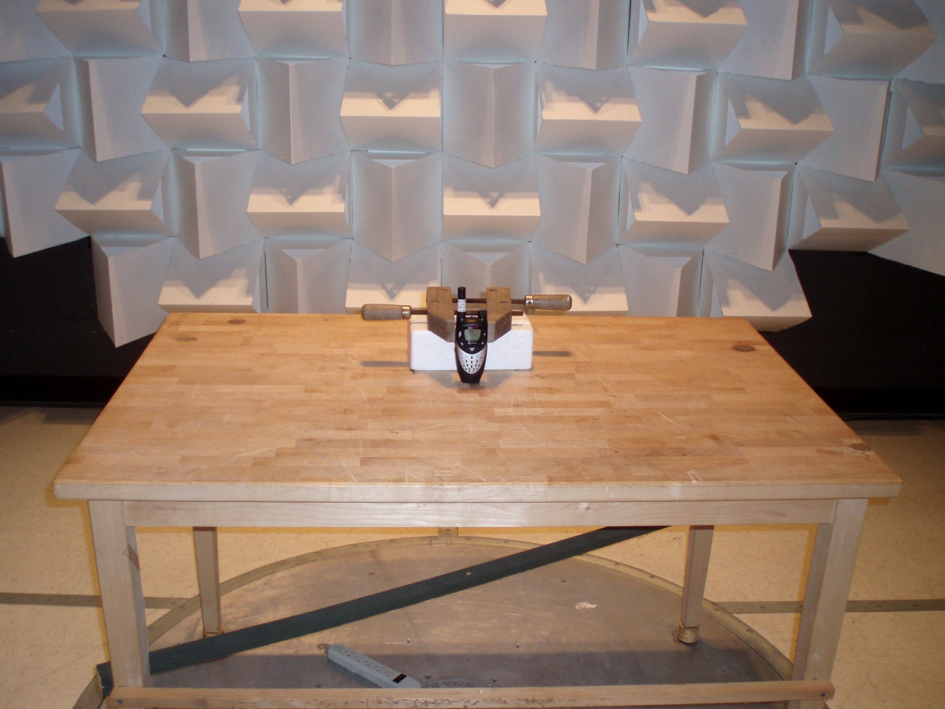
FCC PART 95 AND IC RSS-210 FRS/GMRS TRANSCEIVER TEST REPORT APPLICANT COBRA ELECTRONICS CORPORATION 6500 WEST CORTLAND STREET CHICAGO, IL 60707 USA FCC ID BBO2104B IC CERT # 906B-2104B MODEL NUMBERS CXT425C, CXT428C, CXT430C, CXT475C, CXT478C PRODUCT DESCRIPTION FRS/GMRS TRANSCEIVER DATE SAMPLE RECEIVED 2/9/2010 DATE TESTED 2/22/2010 TESTED BY Nam Nguyen APPROVED BY Mario R. de Aranzeta TIMCO REPORT NO. 350AUT10TestReport.doc TEST RESULTS PASS FAIL THE ATTACHED REPORT SHALL NOT BE REPRODUCED EXCEPT IN FULL WITHOUT THE WRITTEN APPROVAL OF TIMCO ENGINEERING, INC. 849 NW STATE ROAD 45 NEWBERRY, FL 32669 USA PH: 888.472.2424 OR 352.472.5500 FAX: 352.472.2030 EMAIL: [email protected] HTTP://WWW.TIMCOENGR.COM Certificate # 0955-01 Applicant: COBRA ELECTRONICS CORPORATION FCC ID: BBO2104B IC Cert #: 906B-2104B Report: C\COBRA\350AUT10\350AUT10TestReport.doc Page 2 of 19 TABLE OF CONTENTS GENERAL REMARKS ................................................................................................3 GENERAL INFORMATION .........................................................................................4 TEST PROCEDURES ................................................................................................5 RF POWER OUTPUT .................................................................................................6 MODULATION CHARACTERISTICS ...........................................................................7 EMISSION DESIGNATOR AND FREQUENCIES ........................................................ 10 OCCUPIED BANDWIDTH ........................................................................................ 11 SPURIOUS EMISSIONS AT ANTENNA TERMINALS (CONDUCTED) ........................... 13 FIELD STRENGTH OF SPURIOUS EMISSIONS - TX ................................................. 14 FIELD STRENGTH OF SPURIOUS EMISSIONS - RX ................................................. 16 FREQUENCY STABILITY ......................................................................................... 18 TEST EQUIPMENT LIST .......................................................................................... 19 Applicant: COBRA ELECTRONICS CORPORATION FCC ID: BBO2104B IC Cert #: 906B-2104B Report: C\COBRA\350AUT10\350AUT10TestReport.doc Page 3 of 19 GENERAL REMARKS The attached report shall not be reproduced except in full without the written permission of Timco Engineering Inc. Summary The device under test does: fulfill the general approval requirements as identified in this test report not fulfill the general approval requirements as identified in this test report Attestations This equipment has been tested in accordance with the standards identified in this test report. To the best of my knowledge and belief, these tests were performed using the measurement procedures described in this report. All instrumentation and accessories used to test products for compliance to the indicated standards are calibrated regularly in accordance with ISO 17025 requirements. Testing Certificate # 0955-01 I attest that the necessary measurements were made, under my supervision, at: Timco Engineering Inc. 849 NW State Road 45 Newberry, Fl 32669 Authorized Signatory Name: Mario de Aranzeta C.E.T. Compliance Engineer/ Lab. Supervisor Date: 2/25/2010 Applicant: COBRA ELECTRONICS CORPORATION FCC ID: BBO2104B IC Cert #: 906B-2104B Report: C\COBRA\350AUT10\350AUT10TestReport.doc Page 4 of 19 GENERAL INFORMATION The test results relate only to the items tested. DUT Description FRS/GMRS TRANSCEI VER FCC ID BBO2104B IC Cert # 906B-2104B Model Number CXT425C, CXT428C, CXT430C, CXT475C, CXT478C Operating Frequency 462.5500-462.7250, 462.5625-467.7125 No. of Channels 22 Type of Emission 10K5F3E Modulation FM DUT Power Source 110–120Vac/50– 60Hz DC Power Battery Operated Exclusively Test Item Prototype Pre-Production Production Type of Equipment Fixed Mobile Portable Antenna Fixed Test Facility Timco Engineering Inc. located at 849 NW State Road 45 Newberry, FL 32669 USA. Modifications None Test Exercise The DUT was placed in continuous transmit mode of operation Applicable Standards TIA 603 , FCC CFR 47 Part 2 & Part 95, Industry Canada RSS-210 Applicant: COBRA ELECTRONICS CORPORATION FCC ID: BBO2104B IC Cert #: 906B-2104B Report: C\COBRA\350AUT10\350AUT10TestReport.doc Page 5 of 19 TEST PROCEDURES Bandwidth: The measurements were made with the spectrum analyzer's resolution bandwidth (RBW) = 1 MHz and the video bandwidth (VBW) = 3 MHz and the span set as shown on plot. Power Output: RF power was conducted per TIA/EIA STANDARD 603 using the substitution method Antenna Conducted Emissions: The RBW = 100 kHz, VBW = 300 kHz and the span set to 10.0 MHz and the spectrum was scanned from 30 MHz to the 10 th Harmonic of the fundamental. Above 1 GHz the resolution bandwidth was 1 MHz and the VBW = 3 MHz and the span to 50 MHz. Radiation Interference: The test procedure used was TIA 603 using an Agilent spectrum receiver with pre-selector. The bandwidth (RBW) of the spectrum TIA 603 receiver was 100 kHz up to 1 GHz and 1 MHz above 1 GHz with an appropriate sweep speed. The VBW above 1 GHz was 3 MHz. The analyzer was calibrated in dB above a microvolt at the output of the antenna. The ambient temperature of the DUT was 76F with a humidity of 55%. Applicant: COBRA ELECTRONICS CORPORATION FCC ID: BBO2104B IC Cert #: 906B-2104B Report: C\COBRA\350AUT10\350AUT10TestReport.doc Page 6 of 19 RF POWER OUTPUT Rule Part No.: 2.1033(c)(6)(7), 2.1046(a), Part 95, RSS-210 Requirements: Power output shall not exceed 0.50 Watts effective radiated power for the FRS channels. There can be no provisions for increasing the power or varying the power. No GMRS channel, under any condition of modulation, shall exceed: 1. 50W Carrier power (average TP during one modulated RF cycle) when transmitting emissions type A1D, F1D, G1D, A3E, F3E, or G3E. 2. 50W peak envelope TP when transmitting emission type H1D, J1D, R1D, H3E, J3E, or R3E. …
Text truncated - open the document above for the full version.
Contact Information
Applicant
Chris de Waal(Senior Project Engineer)
Test Firm
Timco Engineering, Inc.Bruno Clavier
Technical Specifications
| # | Rule Parts | Frequency Range | Power Output | Emission | Tolerance |
|---|---|---|---|---|---|
| 2 | 95B | 462.5625 MHz - 467.7125 MHz | 400.00 mW | 10K5F3E | 2.5 ppm |
Other Applications from Cobra Electronics Corporation
BBOCHEM01
Jul 21, 2026Radar detector
Equipment Class
CRD - Part 15 Radar DetectorBBOPERF600
Jul 13, 2026PERFORMA 600 RADIO DIGITAL BULK, US/COBRA PERFORMA 600 DIGITAL SINGLE PACK, US/COBRA PERFORMA 600 DIGITAL SIX PACK, US/COBRA PERFORMA 600 DIGITAL RADIO, US
Equipment Class
TNF - Licensed Non-Broadcast Transmitter Held to Face
BBOBB650
May 01, 2026VHF Marine Radio Transceiver
Equipment Class
TNF - Licensed Non-Broadcast Transmitter Held to FaceBBOLESS01
Apr 14, 2026Radar detector with Bluetooth
Equipment Class
DTS - Digital Transmission System
BBOCBPT01
Feb 14, 2023Wireless PTT
Equipment Class
DTS - Digital Transmission System