BBO75WXSTACB Transceiver
Cobra Electronics Corporation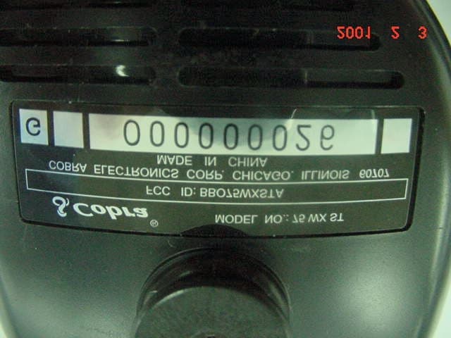
Click to zoom
Application Details
- Equipment Class
- TNB - Licensed Non-Broadcast Station Transmitter
- Date of Grant
- May 02, 2001
- Application Purpose
- Original Equipment
- Date of Application
- Mar 27, 2001
- Equipment Note
- CB Transceiver
- Frequency Range
- 26.96500000 - 27.40500000
- Country
- United States
Documents & Files
Document Text
Text extracted from the exhibit documents filed with the FCC. Open a document above to read the original.
Users Manual
How to Use Your Cobra 75 WX ST Contents Features...........................................................................................1 The CB Story..................................................................................A1 FCC Regulations FCC Warnings Included Accessories Controls & Indicators................................................................A2 Our Thanks to You......................................................................A3 Customer Support Installation Connector Box Location........................................................2 Mounting Connector Box.....................................................3 Mounting and Connections.................................................4 Connecting Wires.....................................................................6 Microphone Hnager................................................................7 Antenna.......................................................................................8 Speakers......................................................................................9 Noise Interference...................................................................9 Operating Your 75 WX ST Turning On Your CB.................................................................10 Setting a Channel.....................................................................10 SoundTracker System.............................................................11 Activating SoundTracker.......................................................12 Testing SoundTracker.............................................................13 Setting the Squelch.................................................................14 LCD Readout..............................................................................16 Receive/Transmit......................................................................17 Emergency Channel 9 & 19..................................................18 Key Lock.......................................................................................20 Frequency Display...................................................................21 All Channel Scan.......................................................................22 Weather Channel......................................................................23 Channel Saver............................................................................24 Memory Channels....................................................................25 Dual Watch.................................................................................26 How Your CB Can Serve You...................................................28 A Few Rules You Should Know............................................28 Channel 9 Emergency Messages.......................................29 CB 10 Codes...............................................................................30 Frequency Ranges......................................................................32 Weather Channels......................................................................33 75 WX ST Specifications..........................................................34 Warranty Information..............................................................35 Optional Accessories.................................................................36 Order Form....................................................................................37 If You Think You Need Service.............................Back Cover Features of This Product • Sound Tracker System •40 CB Radio Channels • 10 Weather Ch a n n e l s • One-Touch Emergency Channel 9 • One-Touch Information Channel 19 • Remote Mount Installation System • Full Featured LCD Display Panel • Squelch Control • Key Lock • Channel Saver Circuitry • Dual Watch Channel Monitor • Full Channel Scan • Four Memory Locations •10 Foot Flexible Cord • Quick Disconnect 1 75 WX ST Manual(5188) 2/5/01 3:00 PM Page 1 Installation 3 Mounting Connector Box Mounting Connect Box Note Make certain that nothing will interfere with the installation of mounting screws, before drilling holes. Hold Cobra 75 WX ST Connector Box in exact location desired for mounting. Using it as a template,mark the location for the mounting screws (included.) 1 2 Mount Connector Box as shown. 3 Location Note Do not mount under the hood,near heat ducts or in direct line of the car’s heater. Under the Front Seat Installation Fire Wall Installation Location Under the Front Seat Installation Mount your Cobra 75 WX ST Connector Box in a convenient location,away from moisture and direct sunlight,in a location that will not interfere with driving. Cobra suggests mounting it either under the front seat or on the fire wall. 2 Installation 75 WX ST Manual(5188) 2/5/01 3:00 PM Page 2 InstallationInstallation Mounting and Connections The Ju n ction Box is held by two scre ws, pe rm i t t i n g mounting in the manner most convenient for your installation. Mounting hardware is supplied for mounting the Junction Box.The mounting must be mechanically s t rong and also provide a good elect ri cal co n n e ct i o n to the chassis of the vehicle. Proceed as follows to mount junction box: Mounting and Connections 5 Caution Leaving the 75 WX ST on after your car is turned off can drain your car batte ry when co n n e cte d to a constant 12 volt source. When co n n e cted to an acce s s o ry 12 volt source the unit will turn off when vehicle is turned off. 4 After you have dete rmined the most co nve n i e nt location in your vehicle,hold the Cobra HH-75 WX ST Junction Box in the exact location desired. If nothing will interfere with mounting it in the desired position,use the Junction Box as a template to mark the location for the mounting screws. Before drilling the holes, make sure nothing will interfere with the installation of the mounting screws. 1 2 3 Connect the antenna cable connector to the antenna receptacle on the unit.Most CB antennas are term…
Text truncated - open the document above for the full version.
External Photos
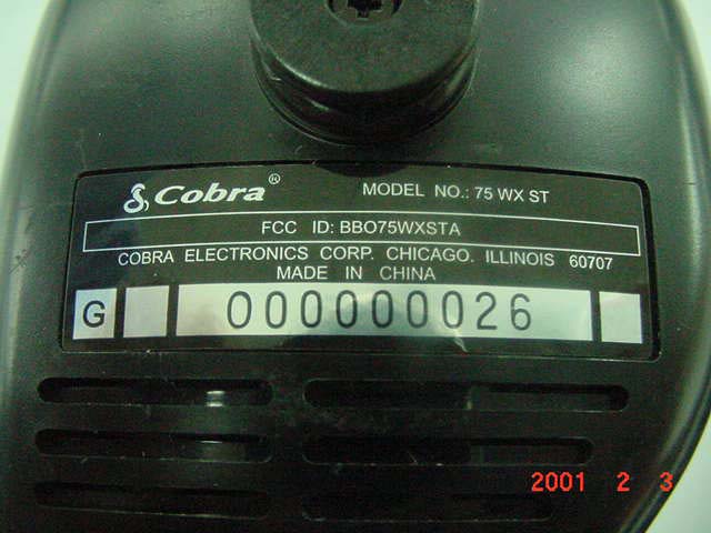
Front View Left Side View Botto m View Back View
Operational Description
APPENDIX 5 FINAL RF AMPLIFIER DATA SHEETS FINAL RF AMP DATA SHEET
Parts List/Tune Up Info
ALIGNMENT PROCEDURE OF 75WS2 REVISION: 00 ENG-75WS2-08 Page: 1 OF 7 Print date: 01-3-28 GIANT ELECTRONICS LTD. ALIGNMENT PROCEDURE MODEL: 75ws2 REVISION: 00 DATE : DEC 19, 2000 PREPARED BY:_____________ CHECKED BY: ____________ APPROVED BY: ____________ TOTAL PAGES: ALIGNMENT PROCEDURE OF 75WS2 REVISION: 00 ENG-75WS2-08 Page: 2 OF 7 Print date: 01-3-28 75WS2 ALIGNMENT INSTRUCTION 1.0 TEST CONDITION: 1.1. STANDARD DC POWER:EXT.DC13.8VDC 1.2. MEASUREMENT CHANNEL:CBCH19 (27.185MHz) WXCH3 (162.475MHz) 1.3. STANDARD AUDIO LOADING:CB/WX8 Ω 1.4. ANTENNA IMPEDANCE:CB/WX50 Ω 1.5. STANDARD REF. MODULATION:CB30% (AM) WX ± 3KHz (FM) 1.6. STANDARD REF. AUDIO OUTPUT:CB/WX0.05W 1.7. FREQUENCY TABLE CB BAND WX BAND CH NO.FREQ. (MHz)CH NO. FREQ. (MHz) 0126.9651162.550 0226.9752162.400 0326.9853162.475 0427.0054162.425 0527.0155162.450 0627.0256162.500 0727.0357162.525 0827.0558161.650 0927.0659161.775 1027.07510163.275 1127.085 1227.105 1327.115 1427.125 1527.135 1627.155 1727.165 1827.175 1927.185 2027.205 2127.215 2227.225 2327.255 2427.235 2527.245 2627.265 2727.275 2827.285 2927.295 3027.305 3127.315 3227.325 3327.335 3427.345 3527.355 3627.365 3727.375 3827.385 3927.395 4027.405 ALIGNMENT PROCEDURE OF 75WS2 REVISION: 00 ENG-75WS2-08 Page: 3 OF 7 Print date: 01-3-28 1.8. TEST EQUIPMENT SETUP AS BELOW: A. TX test equipment setup: Spectrum Power Analyzer Supply Modulation Wattmeter 75WS2 Meter D.U.T. Oscilloscope Frequency Audio Gen. Counter Distortion AC Meter Voltmeter B. RX test equipment setup: SINAD Meter RF Signal Power Generator Supply Distortion 8 ohm 75WS2 Meter loading D.U.T. Oscilloscope Note: D.U.T. = device under test ALIGNMENT PROCEDURE OF 75WS2 REVISION: 00 ENG-75WS2-08 Page: 4 OF 7 Print date: 01-3-28 ALIGNMENT PROCEDURE OF 75WS2 REVISION: 00 ENG-75WS2-08 Page: 5 OF 7 Print date: 01-3-28 2.0 ALIGNMENT 2.1 VCO ALIGNMENT TEST ITEMTEST CONDITION & PROCEDUREPURPOSE 1. CB VCO Voltage1. Connect a digital multi-meter to TP1 2. Set CB RX mode: CH1. Adju st L11 for 1.0 ± 0.1 V. 3. Set CB TX mode Check CH40 ≤ 4.5V. 2. WX VCO Voltage1. Connect a digital multi-meter to TP1 2. Set WX mode CH08. Adju st L1 FOR 1.5 ± 0.1V. Check CH1 0 ≤ 3.0V. 2.2 WX RECEIVER TEST ITEMTEST CONDITION & PROCEDUREPURPOSE 1. Audio output level 1. Set WX mode, CH3. 2. Output of signal generator thru a 0.01 μ F to TP3. 3. RF Gen. set 10.7MHz, Fmod= 1KHz, Dev.= ± 3KHz, RF level: 1mV. 4.Set volume control to middle position. 1. Adju st L9 for maximum audio output & minimum distortion at the distortion meter.(Distortion less than 8% ) 2. Set volume control to maximum position, audio power output shall be more than 0.3 Watts. 2. WX sensitivity1. Output of signal generator to antenna input terminal. 2. RF Gen. set 162.475MHz, Fmod= 1KHz, Dev.= ± 3KHz, RF level: 1 μ V. 3. WX set CH3. 1. Adju st L4 and L3 for more than 12dB at the SINAD meter. 2. Repeat as needed. Check all channels sens. must met D.T.S. 2.3 CB Receiver Alignment TEST ITEMTEST CONDITION & PROCEDUREPURPOSE 1. Audio output level 1. CB RX mode. 2. ST to OFF 3. Output of signal generator thru 0.01uF to TP3. 4. RF Gen. set 10.7MHz, Fmod= 1KHz, AM= 30%, level: 1mV. 1. Adju st L8 and L23 for maximum audio output & minimum distortion at the distortion meter.( Distortion less than 5% ) 2. Set volume control to ALIGNMENT PROCEDURE OF 75WS2 REVISION: 00 ENG-75WS2-08 Page: 6 OF 7 Print date: 01-3-28 5. Set Volume control to middle position. 6. Set Squelch to minimum. maximum position, audio power output shall be more than 0.35 Watts. 2. RX sensitivity 1. Set normal band CH19. 2. Output of signal generator to antenna input terminal. 3. RF Gen. set 27.185MHz, fm: 1kHz, AM= 30%, RF level: 1 μ V. 1. Adju st L5, L6 and L10 for more than 10dB S/N ratio. 2. Repeat as needed. Check CH1 and CH40. 3. SQUELCH control ( Tight Squelch ) 1. Set normal band CH19. 2.Output of signal generator to the antenna input terminal. 3. RF Gen. set 27.185 MHz , Fmod= 1KHz, AM= 30%, RF level: 2000 μ V. 4. Rotate the Squelch control to fully clockwise position 1. Slowly turn VR5 to a position that the audio output waveform at the oscilloscope just appears from no output. 2. Must open at 4000uV. 3. Must not open at 800uV. 4. Signal meter display 1. Set normal band CH19. 2. Output of signal generator to antenna input terminal. RF Gen. set 27.185MHz, no modulation, RF level: 100 μ V. 1. Adju st VR1 for “9” displayed on the signal meter of LCD . 2. Increase RF level by 30dB. The signal meter should be displayed at “+30” position. 5. Sound Tracker ( ST must be on ) a) S/N b) Audio Gain 1. Set normal band CH19. 2. RF Gen. set 27.185MHz,30% modulation 3. S/N @ RF level 1.0uV @ RF level 1000uV 4. Audio Gain @ 100uV 50% Mod. 1. S/N: 1.0uV ≥ 15dB. 1000uV ≥ 50dB. 2. ST audio output change 2-8dB from OFF to ON. 2.4 CB Transmitter Alignment TEST ITEMTEST CONDITION & PROCEDUREPURPOSE 1. TP4 Alignment 1. Channel set normal band CH 19. 2. Set TX mode. Connect the TP4 thru a 10pF capacitor to the oscilloscope. 1. Adjust L24,L21for maximum RF output waveform on the scope. (Freq. = 27.185MHz) 2. Repeat as needed. ALIGNMENT PROCEDURE OF 75WS2 REVISION: 00 ENG-75WS2-08 Page: 7 OF 7 Print date: 01-3-28 2. TX Carrier output power 1. Channel set normal band CH 19. 2. Set TX mode. 3. Connect an RF wattmeter to the antenna socket. 1. Adju st L14 for 4.0 watts RF output power. 2. Check TX CH1 and CH40 should meet D.T.S. 3. TX Carrier frequency detector. 1. Channel set CH 19. 2. Set TX mode. Turn vc1 for 27.185MHz ± 300Hz at the frequency counter. 4. TX Signal meter 1. Connect an RF wattmeter to the antenna socket. 2. No modulation. 3. Set TX output power for 3watts. Adju st VR6 for “3” displayed at the TX signal strength of the LCD. 5. MAXIMUM Modulation (AMC control) 1. Set TX mode. Output of AF generator to MIC jack, @ 1000Hz, 25 mV . ST set off. 1. Adju st VR2 for 88% modulation. 2. Distortion less than 8.0% at 80% modulation. 3. Check CH1,CH40. 6. TX 2 nd harmonics 1. Connect an RF wattmeter to the antenna socket. Reading 2 nd …
Text truncated - open the document above for the full version.
Parts List/Tune Up Info
APPENDIX 4 PLL DATA SHEETS COPY OF PLL DATA SHEETS FCC ID: BBO75WXSTA APPENDIX 4
Test Report
ENGINEERING STATEMENT For Type Acceptance of Cobra Electronics Corporation Model No: 75WXST FCC ID: BBO75WXSTA I am an Electronics Engineer, a principal in the firm of Hyak Laboratories, Inc., Springfield, Virginia. My education and experience are a matter of record with the Federal Communications Commission. Hyak Laboratories, Inc. has been authorized by Cobra Elec- tronics Corporation to make type acceptance measurements on the 75WXST transceiver. These tests were made by me or under my supervision in our Springfield laboratory. Test data and documentation required by the FCC for type acceptance are included in this report. It is submitted that the above-mentioned transceiver meets all applicable FCC requirements. ______________________________ Rowland S. Johnson Dated: March 21, 2001 A. INTRODUCTION The following data are submitted in connection with this request for type acceptance of the 75WXST transceiver in accordance with Part 2, Subpart J of the FCC Rules. The 75WXST is a double sideband, amplitude modulated, transmitter/receiver combination intended for mobile operation in the citizens radio service. The transmitter has 40-channel capability in the 26.965 - 27.405 MHz band utilizing phase locked loop (PLL) technology. It includes weather band channels. B. GENERAL INFORMATION REQUIRED FOR TYPE ACCEPTANCE (Paragraph 2.983 of the Rules) 1. Name of applicant: Cobra Electronics Corporation 2. Identification of equipment: FCC ID: BBO75WXSTA a. The equipment identification included as a separate exhibit. b. Photographs of the equipment are included as a separate exhibit. 3. Quantity production is planned. 4. Technical description: a. 6k00A3E emission b. Frequency range: 26.965 - 27.406 MHz c. Operating power of transmitter is fixed at the factory at less than 4 watts. d. Maximum power rating under 95.635(c) of the Rules is 4 watts. e. The dc voltage and dc currents at final amplifier: Collector voltage: 13.6 V Collector current: 569 mA @ 13.8 Vdc input. f. Function of each active semiconductor device: See Appendix 1. g. Complete circuit diagram is included as a separate exhibit h. A draft instruction book is included as a separate exhibit. i. The transmitter tune-up procedure is included as a separate exhibit. 2 B. GENERAL INFORMATION (Continued) j. A description of circuits for stabilizing frequency is included in Appendix 2. k. A description of circuits and devices employed for suppression of spurious radiation and for limiting modulation is included in Appendix 3. l. Not applicable. 5. Data for 2.985 through 2.997 follow this section. 6. RF_Power_Output (Paragraph 2.985(a),(b)(1) of the Rules) RF power output in the AM mode was measured with a Bird 4421 RF power meter and a Narda 765-20 50 ohm dummy load. (The transmitter was tuned by the factory.) Power was measured with a supply voltage of 13.8 volts, and indicated: Channel Power, watts 1 3.9 21 3.6 40 3.4 C. MODULATION CHARACTERISTICS 1. AF_Frequency_Response A curve showing frequency response of the transmitter is shown in Figure 1. Reference level was taken as a 1 kHz tone with 50% modulation, as measured on a Data Tech 209 modulation meter, using a Audio Precision TRMS voltmeter and tracking generator. 2. Modulation_Limiting Curves of AM modulation limiting for both positive and negative peaks are shown in Figures 2a and 2b, respectively. Characteristics at 300, 960, and 2500 Hz are shown using a Data Tech 209 modulation meter. Signal level was established with a Audio Precision TRMS voltmeter and tracking generator. The curves show compliance with Paragraph 95.633(d) of the Rules. 3 3. Modulation_Limiter_Attack_Time Modulation limiter attack time was measured by applying to the microphone input terminals a pulsed tone at 2500 Hz, 16 dB above the level required for 50% modulation at the frequency of maximum response, 960 Hz. The spectrum analyzer was tuned to upper and lower fourth- order sidebands in the time domain. Horizontal sweep of the analyzer was triggered in synchronism with the tone turn-on. Sweep speed was 100 milliseconds per division. Plots are included as Figures 3a and 3b. Any transients observed in excess of 33 dB attenuation as referenced to the carrier were less than 20 ms in duration. 4 FIGURE 1 TRANSMITTER FREQUENCY RESPONSE TRANSMITTER FREQUENCY RESPONSE FCC ID: BBO75WXSTA FIGURE 1 5 FIGURE 2a AM MODULATION LIMITING - POSITIVE PEAKS MODULATION LIMITING CHARACTERISTICS Percent modulation as a function of input level at microphone jack in dBm for 300 Hz, 960 Hz, and 2500 Hz tones. MODULATION LIMITING POSITIVE PEAKS FCC ID: BBO75WXSTA FIGURE 2a 6 FIGURE 2b AM MODULATION LIMITING - NEGATIVE PEAKS MODULATION LIMITING CHARACTERISTICS Percent modulation as a function of input level at microphone jack in dBm for 300 Hz, 960 Hz, and 2500 Hz tones. MODULATION LIMITING NEGATIVE PEAKS FCC ID: BBO75WXSTA FIGURE 2b 7 FIGURE 3a MODULATION LIMITER ATTACK TIME Measurement_Conditions: 16 dB over 50% modulation level at 960 Hz with 2500 Hz tone, upper fourth order sideband; horizontal scale 100 ms/div. UPPER FOURTH-ORDER SIDEBAND LIMITER ATTACK TIME FCC ID: BBO75WXSTA FIGURE 3a 8 FIGURE 3b MODULATION LIMITER ATTACK TIME Measurement_Conditions: 16 dB over 50% modulation level at 960 Hz with 2500 Hz tone, lower fourth order sideband; horizontal scale 100 ms/div. LOWER FOURTH-ORDER SIDEBAND LIMITER ATTACK TIME FCC ID: BBO75WXSTA FIGURE 3b 9 C. MODULATION CHARACTERISTICS (Continued) 4. Occupied Bandwidth-AM (Para.2.989(c) of the Rules) Figure 4 is a plot of the sideband envelope of the transmitter taken from a Tektronix 494P spectrum ana- lyzer. Modulation corresponded to conditions of 2.989(a) and consisted of 2500 Hz tone at an input level 16 dB greater than that necessary to produce 50% modulation at 960 Hz, the frequency of maximum response. Measured modulation under these conditions was 86% pos., 85% neg. The plots are within the limits imposed by Paragraph 95.631(b)(1,3) for double sideband AM modulation. The horizontal s…
Text truncated - open the document above for the full version.
Contact Information
Applicant
Chris de Waal(Senior Project Engineer)
Technical Contact
Hyak Laboratories, Inc.Rowland S Johnson
[email protected](703) 451-1188
7011 Calamo St., Suite 107 · Springfield, Virginia · United States
Non-Technical Contact
Hyak Laboratories, Inc.Georgia Hall
[email protected](703) 451-1188
Test Firm
Hyak Laboratories, Inc.Rowland Johnson
703-451-1188
Technical Specifications
| # | Rule Parts | Frequency Range | Power Output | Emission | Tolerance |
|---|---|---|---|---|---|
| 1 | 95D | 26.965 MHz - 27.405 MHz | 4 W | 6K00A3E | 0.0050000000 % |
Other Applications from Cobra Electronics Corporation
BBOCHEM01
Jul 21, 2026Radar detector
Equipment Class
CRD - Part 15 Radar DetectorBBOPERF600
Jul 13, 2026PERFORMA 600 RADIO DIGITAL BULK, US/COBRA PERFORMA 600 DIGITAL SINGLE PACK, US/COBRA PERFORMA 600 DIGITAL SIX PACK, US/COBRA PERFORMA 600 DIGITAL RADIO, US
Equipment Class
TNF - Licensed Non-Broadcast Transmitter Held to Face
BBOBB650
May 01, 2026VHF Marine Radio Transceiver
Equipment Class
TNF - Licensed Non-Broadcast Transmitter Held to FaceBBOLESS01
Apr 14, 2026Radar detector with Bluetooth
Equipment Class
DTS - Digital Transmission System
BBOCBPT01
Feb 14, 2023Wireless PTT
Equipment Class
DTS - Digital Transmission System