BBOCABTCB4JJUNCTION BOX WITH BLUETOOTH
Cobra Electronics Corporation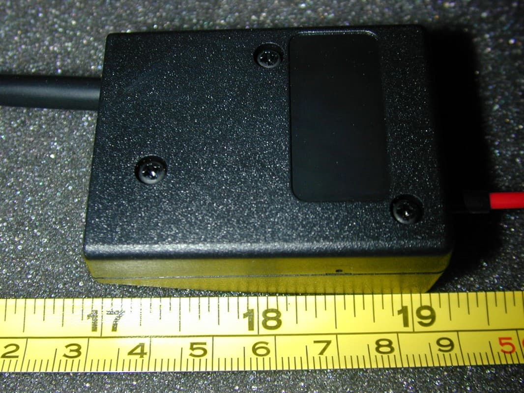
Click to zoom
Application Details
- Equipment Class
- DXX - Part 15 Low Power Communication Device Transmitter
- Date of Grant
- Oct 29, 2012
- Application Purpose
- Original Equipment
- Date of Application
- Oct 29, 2012
- Equipment Note
- JUNCTION BOX WITH BLUETOOTH
- Frequency Range
- 2402.00000000 - 2480.00000000
- Country
- United States
Documents & Files
Document Text
Text extracted from the exhibit documents filed with the FCC. Open a document above to read the original.
Users Manual
©2012 Cobra Electronics Corporation Part No. 480-824-P Printed in Taiwan Version A CA BTCB4 User Manual CABTCB4_MANL.indd 19/6/12 3:21 PM 1 Index 2. Our Thanks to You / Package List 3. Product Illustration 4. Charging the Headset, Installation of the Junction Unit 5. Power On / Off 5. Pairing the Headset (or any Bluetooth ® wireless device) 6. Wearing the Headset, Answering Incoming Calls 6. Refusing Incoming Calls 7. Ending Calls 7. Voice Dialing 7. Redialing Last Call 8. Placing Calls On Hold 8. 3 Way Conference Calling 9. Adjusting the Volume 9. Safety Instruction 10. Transmitting on CB Radio 10. Placing a Call On Hold & Transmitting on CB 11. Specifications 12. Trouble Shooting & Headset Care 13. Q & A 15. FCC Statement / Conditions 17 . Limited 1-Year Warranty CABTCB4_MANL.indd 2-19/6/12 3:21 PM 23 Our Thanks to You Thank you for purchasing the Cobra ® CA BTCB4 wireless microphone system with Bluetooth ® wireless technology. Use for hands-free phone operation and 4-pin CB radios. Properly used, this Cobra product will give you many years of reliable service. Package List Please inspect your packaging contents and refer to the package list below to confirm that there is no shortages or defects. The packaging contents includes the following items: ► • Over-the-Head Microphone System ................................................1 ► • 4-Pin Junction Unit ......................................................................1 ► • Push-to-Talk Switch ......................................................................1 • Retaining Cable Clips (not shown) .................................................6 ► • USB Cable ..................................................................................1 ► • 12V Cigarette Lighter Plug Vehicle Charger .....................................1 • Product Registration Card ..............................................................1 • Hook and Loop Material (not shown) .............................................1 • PTT Switch Cushion (not shown) ...................................................1 If you find any shortage or defect, please contact your retailer where you purchased the product. Product Illustration 1. Power Switch 2. Multi-Function Button (Answer/End Calls) 3. Volume Up (+) 4. Indicator Light 5. Volume Down (-) 6. Charging Jack Port 7. Speaker (Receiver) 8. Microphone 9. Junction Unit 10. Push-to-Talk Jack 11. CB-In-Use Indicator 12. Fuse 13. 4-Pin CB Mic Connector 14. 12V DC Power Lead 15. Push-to-Talk Button Charging Accessories USB Charging Cable Vehicle Charger 1. POWER SWITCH 2. MULTI-FUNCTION BUTTON 3. VOLUME UP BUTTON 4. INDICATOR LIGHT 5. VOLUME DOWN BUTTON 6. CHARGING JACK PORT 7. SPEAKER PHONE 8. MICROPHONE 9. JUNCTION UNIT 11. CB IN USE INDICATOR 10. PUSH-TO-TALK JACK 12. FUSE 13. 4-PIN CB CONNECTOR 14. 12V DC POWER LEAD 15. PUSH-TO-TALK BUTTON CABTCB4_MANL.indd 2-39/6/12 3:21 PM 45 4. Charging the Headset The CA BTCB4 includes a rechargeable built-in Lithium Polymer battery. IMPORTANT: For first time use, charge the headset for at least 2 hours before pairing. 1. Insert the USB charging cable into the charging jack port located on the side of the headset. 2. Plug other end of USB charging cable into a PC or insert the USB cable into the cigarette adaptor and place into a working cigarette lighter outlet. 3. During charging the indicator will glow a steady red light 4. When charging is complete, the indicator light will turn off. NOTE: • Do not attempt to use headset while charging. • Only use the supplied charger or original Cobra products to charge the headset. • When headset battery charge is low, the indicator light will flash red. • Do not charge the headset for more than 24 hours. • Recharge headset only within a temperature range of 14°F to 113°F. 5. Installation of the Junction Unit 1. Connect the 4-pin cable of the junction unit to CB microphone connector. 2. Attach hook and loop material to back of junction unit. 3. Attach junction unit with hook and loop to a convenient location near the CB radio. 4. Connect the Red power cable to a 12V DC power source. You can use the same source as the CB. 5. Connect the Push-to-Talk plug the PTT connector to the junction unit. 6. Route the PTT cable preferably to the stick-shift. Use retaining clips (included) to secure cable. 7. Charge the headset for approximately 2 hours. 8. Pair the headset to the cellphone (see page 5). 9. The headset and junction unit should pair automatically. You will hear an audible tone on the handset once the connection is made for CB use. 6. Power On/Off 1. To power on, press and hold the power button for 1 second, the power will turn on after the indicator flashes a blue light 3 times (the blue light will continuously flash 1 time per second). 2. To power off, press and hold the power button for 6 seconds until you hear 1 beep and the red LED will light momentarily. 7. Pairing the Headset IMPORTANT: Your Cobra Bluetooth headset and your Bluetooth wireless technology enabled phone or other device, must be “paired” before first time use. 1. Ensure the headset is on. 2. Press and hold the multi-function button until the indicator flashes blue/red (the headset is in pairing mode). 3. Ensure your mobile phone has the Bluetooth wireless technology function and start the new device searching function. Please follow the instructions of your mobile phone to proceed the operation. 4. Activate the Bluetooth “discovery” function in the mobile phone or other Bluetooth device. Example: Menu/Bluetooth/add new device. (See phone manual for specific Bluetooth wireless technology pairing instructions.). 6. When the headset is recognized by your phone, “CA BTCB4” will appear in the list of found devices. 7. Scroll to select or highlight “CA BTCB4” and press OK. 8. On some phones, you will be prompted to enter the headset password “0000”, press OK. 9. If pairing is successful, your headset’s indicator will flash blue 3 times every 10 seconds. If pairing is…
Text truncated - open the document above for the full version.
External Photos
COBRA ELECTRONICS CORP. FCC ID: BBOCABTCB4J IC: 906A-CABTCB4J EXTERNAL PHOTOS
ID Label/Location Info
CA BTCB4 JUNCTION BOX SERIAL NUMBER TEMPLATE SILVER LABEL, BLACK TEXT 1:1 30 mm 14 mm REV 10/15/12 MODEL NO: CA BTCB4J www.cobra.com CA BTCB4 SAMPLE SERIAL NUMBER TEMPLATE SILVER LABEL, BLACK TEXT 2:1 MADE IN TAIWAN FCC ID: BBOCABTCB4J IC:906A-CABTCB4J MODEL NO: CA BTCB4J www.cobra.com MADE IN TAIWAN FCC ID: BBOCABTCB4J IC:906A-CABTCB4J MODEL NO: CA BTCB4J www.cobra.com MADE IN TAIWAN FCC ID: BBOCABTCB4J IC:906A-CABTCB4J
Internal Photos
COBRA ELECTRONICS CORP. FCC ID: BBOCABTCB4J IC: 906A-CABTCB4J INTERNAL PHOTOS
Test Report
FCC PART 15.249 AND IC RSS-210 TEST REPORT UNLICENSED INTENTIONAL RADIATOR Applicant COBRA ELECTRONICS CORPORATION Address 6500 WEST CORTLAND STREET CHICAGO IL 60707 USA FCC ID BBOCABTCB4J IC 906A-CABTCB4J Model Number CA BTCB4 Product Description JUNCTION BOX WITH BLUETOOTH Date Sample Received 9/12/2012 Date Tested 9/18/2012 Tested By Nam Nguyen Approved By Mario de Aranzeta Report Number 2375AUT12TestReport.doc Test Results PASS FAIL THE ATTACHED REPORT SHALL NOT BE REPRODUCED EXCEPT IN FULL WITHOUT THE WRITTEN APPROVAL OF TIMCO ENGINEERING, INC. 849 NW State Road 45 Newberry, FL 32669 USA Ph: 888.472.2424 or 352.472.5500 Fax: 352.472.2030 Email: [email protected] Website: www.timcoengr.com Certificate # 0955-01 APPLICANT: COBRA ELECTRONICS CORPORATION FCC ID: BBOCABTCB4J IC: 906A-CABTCB4J REPORT: C\COBRA\2375AUT12\2375AUT12TestReport.doc Page 2 of 16 Mdea 9.20.2007 TABLE OF CONTENT GENERAL REMARKS ................................................................................................................. 3 GENERAL INFORMATION .......................................................................................................... 4 EMC EQUIPMENT LIST .............................................................................................................. 5 TEST PROCEDURES .................................................................................................................. 6 RADIATION INTERFERENCE ..................................................................................................... 7 OCCUPIED BANDWIDTH ........................................................................................................... 9 BAND EDGE COMPLIANCE ..................................................................................................... 11 POWER LINE CONDUCTED INTERFERENCE ........................................................................... 16 APPLICANT: COBRA ELECTRONICS CORPORATION FCC ID: BBOCABTCB4J IC: 906A-CABTCB4J REPORT: C\COBRA\2375AUT12\2375AUT12TestReport.doc Page 3 of 16 Mdea 9.20.2007 GENERAL REMARKS The attached report shall not be reproduced except in full without the written permission of Timco Engineering Inc. Summary The device under test does: fulfill the general approval requirements as identified in this test report not fulfill the general approval requirements as identified in this test report Attestations This equipment has been tested in accordance with the standards identified in this test report. To the best of my knowledge and belief, these tests were performed using the measurement procedures described in this report. All instrumentation and accessories used to test products for compliance to the indicated standards are calibrated regularly in accordance with ISO 17025: 2005 requirements. Certificate # 0955-01 I attest that the necessary measurements were made, under my supervision, at: Timco Engineering Inc. 849 NW State Road 45 Newberry, Fl 32669 Authorized Signatory Name: Mario de Aranzeta C.E.T. Compliance Engineer/ Lab. Supervisor Date: September/24/2012 APPLICANT: COBRA ELECTRONICS CORPORATION FCC ID: BBOCABTCB4J IC: 906A-CABTCB4J REPORT: C\COBRA\2375AUT12\2375AUT12TestReport.doc Page 4 of 16 Mdea 9.20.2007 GENERAL INFORMATION DUT Specification The test results relate only to the items tested. Applicable Standard Part 15.249, RSS-210, RSS-GEN DUT Description JUNCTION BOX WITH BLUETOOTH FCC ID BBOCABTCB4J IC 906A-CABTCB4J Model Number CA BTCB4 Operating Frequency TX: (2400 – 2483.5) MHz RX: Same No. of Channels 79 Modulations DUT Power Source 110–120Vac/50– 60Hz DC Power Battery Operated Exclusively Test Item Prototype Pre-Production Production Type of Equipment Fixed Mobile Portable Antenna Connector FCC Rules require that the antenna connector be unique. Test Facility Timco Engineering Inc. located at 849 NW State Road 45 Newberry, FL 32669 USA. Test Conditions Temperature: 26ºC Relative humidity: 50% Test Exercise The DUT was placed in continuous transmit mode of operation. Modifications Test Supporting Equipment Supporting Device Manufacturer Model / FCC ID Serial Number CB radio Cobra Electronics 19 DX IV EU APPLICANT: COBRA ELECTRONICS CORPORATION FCC ID: BBOCABTCB4J IC: 906A-CABTCB4J REPORT: C\COBRA\2375AUT12\2375AUT12TestReport.doc Page 5 of 16 Mdea 9.20.2007 EMC EQUIPMENT LIST Device Manufacturer Model Serial Number Cal/Char Date Due Date 3-Meter Semi- Anechoic Chamber Panashield N/A N/A Listed 12/31/11 12/31/13 AC Voltmeter HP 400FL 2213A14499 CAL 6/12/11 6/12/13 Antenna: Active Loop ETS-Lindgren 6502 00062529 CAL 9/23/10 9/23/12 Frequency Counter HP 5385A 2730A03025 CAL 8/17/11 8/17/13 Hygro- Thermometer Extech 445703 0602 CAL 6/15/11 6/15/13 Modulation Analyzer HP 8901A 3435A06868 CAL 7/18/11 7/18/13 Digital Multimeter Fluke FLUKE-77 35053830 CAL 9/9/11 9/9/13 Power Meter Boonton Electronics 4531 11793 CAL 11/12/2010 11/12/2012 EMI Receiver Rohde & Schwarz ESIB40 100274 CAL 3/16/2012 3/16/2014 Analyzer Tan Tower Preamplifier HP 8449B-H02 3008A00372 CAL 10/28/11 10/28/13 Analyzer Tan Tower Quasi- Peak Adapter HP 85650A 3303A01690 CAL 10/28/11 10/28/13 Analyzer Tan Tower RF Preselector HP 85685A 3221A01400 CAL 10/28/11 10/28/13 Analyzer Tan Tower Spectrum Analyzer HP 8566B Opt 462 3138A07786 3144A20661 CAL 10/28/11 10/28/13 Temperature Chamber Tenney Engineering TTRC 11717-7 CHAR 2/22/12 2/22/13 Antenna ETS 3117 35923 12/7/2011 12/7/2013 Antenna Electro metrics LPA-25 1122 5/04/2011 5/04/2013 Antenna Electro metrics BIA-25 1096 5/04/2011 5/04/2013 APPLICANT: COBRA ELECTRONICS CORPORATION FCC ID: BBOCABTCB4J IC: 906A-CABTCB4J REPORT: C\COBRA\2375AUT12\2375AUT12TestReport.doc Page 6 of 16 Mdea 9.20.2007 TEST PROCEDURES Radiation Interference: ANSI C63.4-2003 using a spectrum analyzer, a preselector, a quasi- peak adapter, and an appropriate antenna. The analyzer was calibrated in dB above a microvolt at the output of the antenna. The resolution bandwidth was 100 kHz with an appropriate sweep speed and t…
Text truncated - open the document above for the full version.
Contact Information
Applicant
Chris de Waal(Senior Project Engineer)
Test Firm
Timco Engineering, Inc.Bruno Clavier
Technical Specifications
| # | Rule Parts | Frequency Range | Power Output |
|---|---|---|---|
| 1 | 15C | 2.40 GHz - 2.48 GHz | - |
Other Applications from Cobra Electronics Corporation
BBOCHEM01
Jul 21, 2026Radar detector
Equipment Class
CRD - Part 15 Radar DetectorBBOPERF600
Jul 13, 2026PERFORMA 600 RADIO DIGITAL BULK, US/COBRA PERFORMA 600 DIGITAL SINGLE PACK, US/COBRA PERFORMA 600 DIGITAL SIX PACK, US/COBRA PERFORMA 600 DIGITAL RADIO, US
Equipment Class
TNF - Licensed Non-Broadcast Transmitter Held to Face
BBOBB650
May 01, 2026VHF Marine Radio Transceiver
Equipment Class
TNF - Licensed Non-Broadcast Transmitter Held to FaceBBOLESS01
Apr 14, 2026Radar detector with Bluetooth
Equipment Class
DTS - Digital Transmission System
BBOCBPT01
Feb 14, 2023Wireless PTT
Equipment Class
DTS - Digital Transmission System