BBODSP9200Radar Detector with Bluetooth
Cobra Electronics Corporation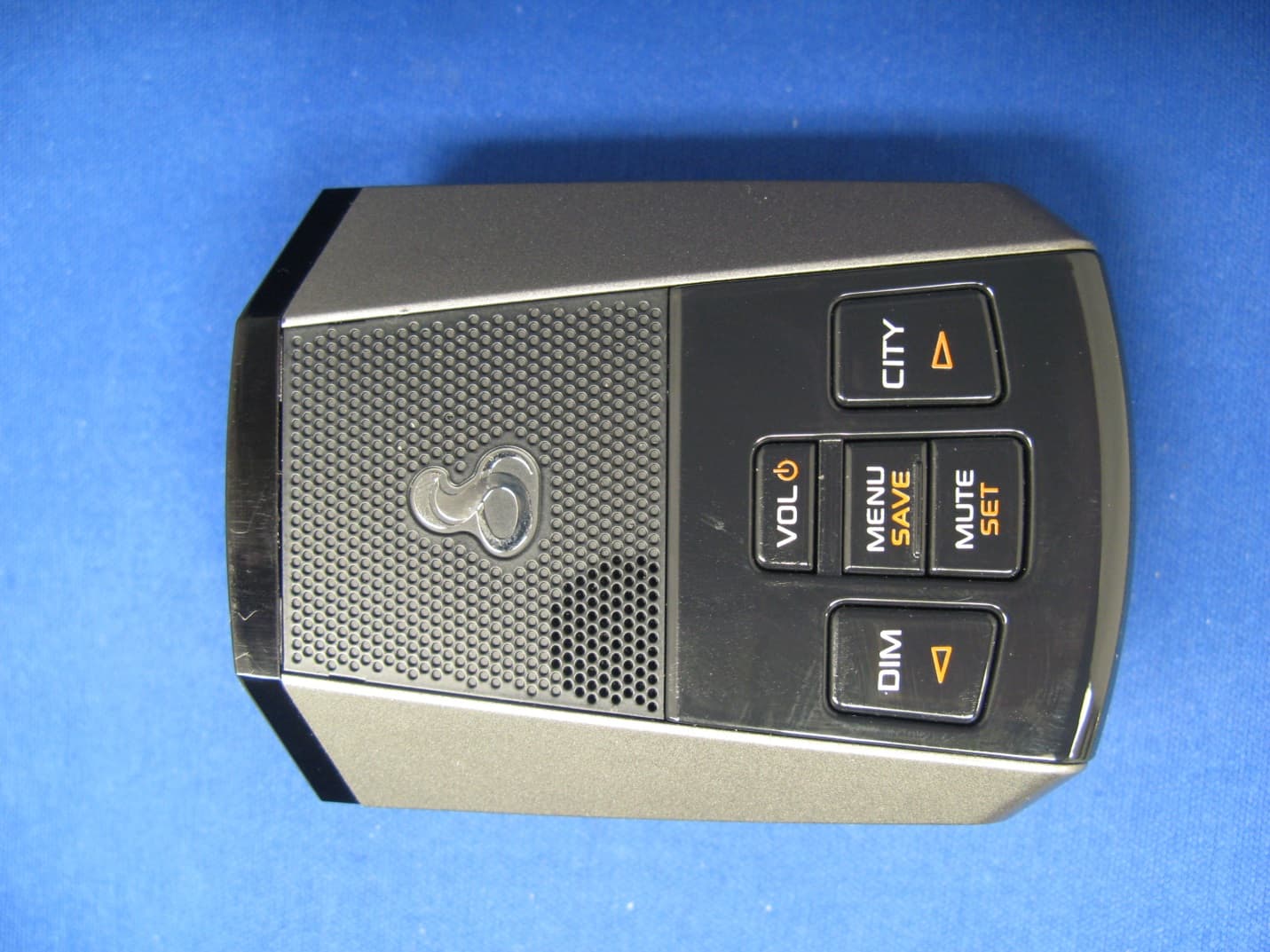
Click to zoom
Application Details
- Equipment Class
- DXX - Part 15 Low Power Communication Device Transmitter
- Date of Grant
- May 11, 2015
- Application Purpose
- Original Equipment
- Date of Application
- May 11, 2015
- Equipment Note
- Radar Detector with Bluetooth
- Frequency Range
- 2400.00000000 - 2483.20000000
- Country
- United States
Documents & Files
Document Text
Text extracted from the exhibit documents filed with the FCC. Open a document above to read the original.
Users Manual
Frequency Display Mode Advanced This is a new advanced and very useful mode. A graph is shown with the detected radar frequency and where it falls in relation to the center frequency of the closest radar gun. The closer the signal strength bar is to the center of the display the more likely it’s a high priority real alert. Laser Alert Screens With Laser signals, you will always receive full alert. The word LASER will be shown on the display. The color of the word LASER indicates the iRadar threat area level. When connected to the Cobra iRadar app, the LaserRelay™ feature will be activated. Laser alerts will be simultaneously relayed to other users of a detector with iRadar functionality. Frequency Display Mode On This is a more advanced mode. The exact frequency of the detected radar signal will also be shown. Dual Lock ® Mount Radar/Laser/Camera Detector DSP 9200BT Operating Instructions Printed in the Philippines Part No. 480-1030-P Version A Thank you for purchasing Cobra’s new digital ultra-performance radar/laser/camera detector. Windshield Bracket Mounting Slot Power/Volume Button Mini-USB 5V Power Jack Menu/Report Button • Press once to enter Menu Mode. • Press and Hold to make a User Report* Mute/Down Button • While alerting, press once to manually mute audio alerts. • In Standby and connected to the app, press once to toggle between available standby screens. City/ Button • Switches between Highway and City ltering modes. • In Menu mode, steps forward through menu options. Dim/ Button • Adjusts the display brightness. • In Menu mode, steps backward through menu options. Mounting Your detector should be mounted on the windshield or dashboard of your vehicle. Three mounting options are included: Suction Cup Mount – This is the best option for portability and mov- ing the detector from car to car. Make sure to thoroughly clean the suction cups and windshield mounting area to insure a tight seal. Dual Lock ® Mount – This mount is discreet and very solid for a permanent mounting location. Make sure the adhesive side of the included Dual Lock is securely fastened to the windshield before adding the weight of the detector to it. Hook and Loop Fastener– Included for dashboard mounting. Suction Cup Mount Hook & Loop Fastener Your detector should be mounted so that it is oriented parallel to the road. The suction cup mount comes standard bent at a 45° angle and Dual Lock ® at 30° angle. The metal is designed to bend without break- ing. Adjust the angle so when mounted the detector is level with the road. Windshield Incorrect Positions Correct Position Powering Plug in your detector using the included cigarette lighter adapter. This adapter has a Mini-USB 5V output. Note: the adapter includes a Type-A USB port that can be used to charge your smartphone or tablet using the manufac- turer’s charging cable. Turn your detector On/Off by pressing and holding the Power/Volume button on top of the unit. 12V Cigarette Lighter Adapter 12V Power Jack USB Port Menu/Settings Screen Settings are available for customizing your detector. When Menu is pressed, you will see will see the detec- tor display the word MENU and then X-Alert. From this Menu Mode, press the Button to step through the available Alert and User Settings. Press the button to change the selected setting. The Settings options are: Alert Screens and Settings Radar bands consist of X-band, K-band, and Ka-band. With Radar signals, the signal strength meter shows signal strength of the radar gun giving the relative proximity to the source. The Settings Menu allows turning these bands On and Off. In addi- tion, this detector has three modes for displaying these radar band alerts. Frequency Display Mode On, Off, and Advanced can be se- lected from the Settings Menu. The default is Off, but Cobra would recommend switching to Advanced after reading this manual and understanding the alerts graphics on the following page. Color Coded Threat Areas* When connected to the Cobra iRadar app, the color of the Radar Band, Laser or Location Based Alerts and Standby Screens will change. The color indicates the threat level for the area your ve- hicle is located. The threat level is calculated by Cobra’s powerful servers and displayed on your smart phone and the detector. White= Not Connected, Blue= Low Threat Level, Orange= Medium Threat Area, Red= High Threat Area. • Press and Hold to turn the power On and Off. • Press to adjust the volume. No connection to phone. City Max lter mode selected. Connected to phone. Vehicle heading north west at 55 Mph. Radar Alerts Frequency Display Mode Off This is the basic alert mode. It shows the radar alert band and signal strength. X-Alert K-Alert Ka-Alert Frequency Auto Mute Audio Controls and Connections NOTE: This device complies with part 15 of FCC rules: Operation is subject to the following two conditions: (1) This device may not cause harmful interference, and (2) This device must accept any interference received including interference that may cause undesired operation. CAUTION: Modifications or parts not approved by Cobra Electronics Corporation may violate FCC Rules and void authority to operate this equipment. This device complies with Industry Canada licence-exempt RSS standard(s). Operation is subject to the following two conditions: (1) this device may not cause interference, and (2) this device must accept any interference, including interference that may cause undesired operation of the device. Le présent appareil est conforme aux CNR d’Industrie Canada applicables aux appareils radio exempts de licence. L’exploitation est autorisée aux deux conditions suivantes : (1) l’appareil ne doit pas produire de brouillage, et (2) l’utilisateur de l’appareil doit accepter tout brouillage radioélectrique subi, même si le brouillage est susceptible d’en compromettre le fonctionnement. US Pat. Nos. 6078279, 8842004, 8970422 and other US Patents Pending • In standby, Press and Hold to turn Quiet Drive On and Off.…
Text truncated - open the document above for the full version.
Cover Letter(s)
Equipment Authorization Division Office of Engineering and Technology Federal Communications Commission 7435 Oakland Mills Road Columbia, MD 21046 Ref: FCC ID: BBODSP9200 Request for Confidentiality Dear Sirs: With regard to the referenced application, Cobra Electronics Corp. is requesting confidentiality of certain sections of the accompanying documents. The documents for which Cobra Electronics Corp. is requesting confidentiality are: DSP9200 Block Diagram DSP9200 Circuits (Schematics) DSP9200 Theory of operation This request is made under the provisions of Section 0.457(d) of the Commission’s Rules, and Section 552(b)(4) of the Freedom of Information Act. The material for which confidentiality is requested falls within the scope of Section 552(b)(4) as trade secrets and includes material covered by Section 0.459 of the Commission’s Rules. Pursuant to DA 04-1705 June 15, 2004 of the Commission’s public notice, we also request temporary confidential treatment of information accompanying this application as outlined below until the end of July, 2015 (expected ship date): DSP9200 External Photos DSP9200 Test Setup Photos DSP9200 Manual DSP9200 Internal Photos Sincerely, Chris deWaal Sr. Project Engineer
External Photos
APPLICANT: COBRA ELECTRONICS CORP. FCC ID: BBODSP9200 EXTERNAL PHOTOS
Internal Photos
APPLICANT: COBRA ELECTRONICS CORP. FCC ID: BBODSP9200 INTERNAL PHOTOS
Test Report
FCC PART 15.249 TEST REPORT UNLICENSED INTENTIONAL RADIATOR Applicant COBRA ELECTRONICS CORPORATION Address 6500 WEST CORTLAND STREET CHICAGO IL 60707 USA FCC ID BBODSP9200 Model Number DSP 9200BT Product Description RADAR DETECTOR WITH BLUETOOTH Date Sample Received 4/6/2015 Date Tested 4/23/2015 Tested By Sid Sanders Approved By Cory Leverett Test Results PASS FAIL Report Number Version Number Description Issue Date 644AUT15TestReport.docx Rev.1 Initial Issue 4/23/2015 644AUT15TestReport.docx Rev.2 Corrected FCC ID 5/13/2015 THE ATTACHED REPORT SHALL NOT BE REPRODUCED EXCEPT IN FULL WITHOUT THE WRITTEN APPROVAL OF TIMCO ENGINEERING, INC. 849 NW State Road 45 Newberry, FL 32669 USA Ph: 888.472.2424 or 352.472.5500 Fax: 352.472.2030 Email: [email protected] Website: www.timcoengr.com TABLE OF CONTENTS GENERAL REMARKS ..................................................................................................... 2 GENERAL INFORMATION ............................................................................................... 3 TEST RESULTS SUMMARY ............................................................................................. 3 RADIATION INTERFERENCE........................................................................................... 4 OCCUPIED BANDWIDTH & Bandedge: ............................................................................. 6 EMC EQUIPMENT LIST .................................................................................................. 7 APPLICANT:COBRA ELECTRONICS CORPORATION FCC ID: BBODSP9200 REPORT: C\COBRA\644AUT15\644AUT15TestReport.docx Page 2 of 7 GENERAL REMARKS The attached report shall not be reproduced except in full without the written permission of Timco Engineering Inc. Summary The device under test does: fulfill the general approval requirements as identified in this test report not fulfill the general approval requirements as identified in this test report Attestations This equipment has been tested in accordance with the standards identified in this test report. To the best of my knowledge and belief, these tests were performed using the measurement procedures described in this report. All instrumentation and accessories used to test products for compliance to the indicated standards are calibrated regularly in accordance with ISO 17025: 2005 requirements. I attest that the necessary measurements were made, under my supervision, at: Timco Engineering Inc. 849 NW State Road 45 Newberry, Fl 32669 Authorized Signatory Name: Sid Sanders Project Manager Date: 4/27/2015 Table of Contents APPLICANT:COBRA ELECTRONICS CORPORATION FCC ID: BBODSP9200 REPORT: C\COBRA\644AUT15\644AUT15TestReport.docx Page 3 of 7 GENERAL INFORMATION EUT Specification The test results relate only to the items tested. EUT Description Bluetooth in radar detector FCC ID BBODSP9200 Model Number DSP 9200BT Operating Frequency TX: 2400-2483.2MHz RX: Same No. of Channels Modulations EUT Power Source 110–120Vac/50– 60Hz DC Power Battery Operated Exclusively Test Item Prototype Pre- Production Production Type of Equipment Fixed Mobile Portable Antenna Connector NA Test Facility Timco Engineering Inc. located at 849 NW State Road 45 Newberry, FL 32669 USA. Conditions in the Test laboratory Temperature: 26ºC Relative humidity: 50% Test Exercise The EUT was placed in continuous transmit mode of operation at 3 places in the band. Applicable Standard Part 15.249 Method of Measurement ANSI C63.4 2003 Test Supporting Equipment Supporting Device Manufacturer Model / FCC ID Serial Number N/A TEST RESULTS SUMMARY Specification – Rules Part No. RESULTS – Pass/Fail/NA FCC Rule 15.249 Fundamental PASS FCC Rule 15.249 Harmonics & Spurious PASS Bandedge PASS Power Line Emissions 15.207 NA Table of Contents APPLICANT:COBRA ELECTRONICS CORPORATION FCC ID: BBODSP9200 REPORT: C\COBRA\644AUT15\644AUT15TestReport.docx Page 4 of 7 RADIATION INTERFERENCE Rules Part No.: 15.249, 15.209 Requirements: Frequency Limits Part 15.209 9 to 490 kHz 2400/F (kHz) μV/m @ 300 meters 490 to 1705 kHz 24000/F (kHz) μV/m @ 30 meters 1705 kHz to 30 MHz 29.54 dBμV/m @ 30 meters 30 – 88 40.0 dBμV/m @ 3 meters 80 – 216 43.5 dBμV/m @ 3 meters 216 – 960 46.0 dBμV/m @ 3 meters Above 960 54.0 dBμV/m @ 3 meters Part 15.249 Fundamental 902 – 928 MHz 94.0 dBμV/m @ 3 meters Fundamental 2.4 – 2.4835 GHz 94.0 dBμV/m @ 3 meters Harmonics 54.0 dBμV/m @ 3 meters Method of Measurement: ANSI C63.4 using a spectrum analyzer, a preselector, a quasi- peak adapter, and an appropriate antenna. The analyzer was calibrated in dB above a microvolt at the output of the antenna. The resolution bandwidth was 100 kHz with an appropriate sweep speed and the video bandwidth was 300 kHz up to 1 GHz and 1 MHz with a video BW of 3 MHz above 1 GHz. When an emission was found, the table was rotated to produce the maximum signal strength. The antenna was placed in both the horizontal and vertical planes and the worst case emissions were reported. The spectrum was searched to at least the tenth (10) harmonic of the fundamental. Formula Of Conversion Factors: The field strength at 3m was established by adding the meter reading of the spectrum analyzer (which is set to read in units of dBuV) to the antenna correction factor supplied by the antenna manufacturer. The antenna correction factors are stated in terms of dB. The gain of the preselector was accounted for in the spectrum analyzer meter reading. Example: Freq (MHz) Meter Reading + ACF + CL = FS 33 20 dBuV + 10.36 dB + 0.5 = 30.86 dBuV/m @ 3m Table of Contents APPLICANT:COBRA ELECTRONICS CORPORATION FCC ID: BBODSP9200 REPORT: C\COBRA\644AUT15\644AUT15TestReport.docx Page 5 of 7 RESTRICTED BANDS OF OPERATION RULE PART: 15.205 REQUIREMENT: Above 1000 MHz, compliance with the emission limits in §15.209 shall be demonstrated based on the average value of the measured emissions. The provisions in §15.35 apply to these measurements. Method of Measurement: ANSI C63.4 The Restricted Bands …
Text truncated - open the document above for the full version.
Test Setup Photos
APPLICANT: COBRA ELECTRONICS CORP. FCC ID: BBODSP9200 TEST SET UP PHOTOS
Contact Information
Applicant
Chris de Waal(Senior Project Engineer)
Technical Contact
Timco Engineering, Inc.Sid Sanders
[email protected]888-472-2424
849 NW State Road 45 · Newberry, Florida · United States
Non-Technical Contact
Timco Engineering, Inc.Sharon Hoffman
[email protected]888-472-2424
Test Firm
Timco Engineering, Inc.Bruno Clavier
Technical Specifications
| # | Rule Parts | Frequency Range | Power Output |
|---|---|---|---|
| 1 | 15C | 2.40 GHz - 2.48 GHz | - |
Other Applications from Cobra Electronics Corporation
BBOCHEM01
Jul 21, 2026Radar detector
Equipment Class
CRD - Part 15 Radar DetectorBBOPERF600
Jul 13, 2026PERFORMA 600 RADIO DIGITAL BULK, US/COBRA PERFORMA 600 DIGITAL SINGLE PACK, US/COBRA PERFORMA 600 DIGITAL SIX PACK, US/COBRA PERFORMA 600 DIGITAL RADIO, US
Equipment Class
TNF - Licensed Non-Broadcast Transmitter Held to Face
BBOBB650
May 01, 2026VHF Marine Radio Transceiver
Equipment Class
TNF - Licensed Non-Broadcast Transmitter Held to FaceBBOLESS01
Apr 14, 2026Radar detector with Bluetooth
Equipment Class
DTS - Digital Transmission System
BBOCBPT01
Feb 14, 2023Wireless PTT
Equipment Class
DTS - Digital Transmission System