BBOESD9851RADAR DETECTOR
Cobra Electronics Corporation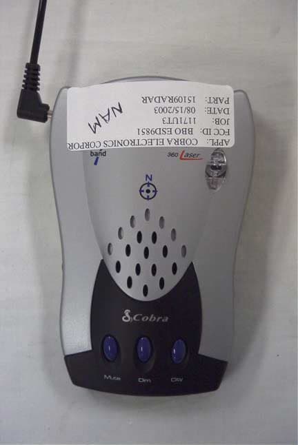
Click to zoom
Application Details
- Equipment Class
- CRD - Part 15 Radar Detector
- Date of Grant
- Sep 14, 2003
- Application Purpose
- Original Equipment
- Date of Application
- Sep 14, 2003
- Equipment Note
- RADAR DETECTOR
- Frequency Range
- 33400.00000000 - 36000.00000000
- Country
- United States
Documents & Files
Document Text
Text extracted from the exhibit documents filed with the FCC. Open a document above to read the original.
Users Manual
How to Use Your Cobra ESD Radar/Laser Detector 1 Features of This Product •8-point Digital Compass • Alpha/Numeric Dot Matrix Text Readout • Safety Alert® Traffic Warning System •Strobe Alert ™ • Tone Alert • Voice Alert • Separate Visual and Audio Alarms • Laser Eye 360 ̊ De te ct i o n • VG-2 Undete ct a b l e • Au to and Manual Muting • 4 Level Dim Bu t to n • Audio Jack • Superior Audio Volume • Adjustable Windshield Mounting Bra c ke t Contents Introduction..................................................................A1 Safety Alert®/Strobe Alert™ Federal Law Governing Radar Detectors Included Accessories Controls & Indicators................................................A2 Our Thanks to You......................................................A3 Customer Support...................................................A3 Features.............................................................................1 Installation.......................................................................2 Quick Start.......................................................................5 Digital Displays............................................................6 Operation..........................................................................9 Turning On....................................................................9 Dim Button.................................................................10 Highway/City Mode.................................................12 Muting Mode.............................................................13 Calibrate the Compass...........................................15 Tone/Voice Alert.......................................................16 Memory Set................................................................17 Aux.Audio Jack.........................................................17 Detection........................................................................18 Band Detection.........................................................18 Audible Alarm Indicator.........................................18 Radar.................................................................................18 VG-2 Undetectable..................................................19 Safety Alert®/Strobe Alert™.................................20 Laser Detection.........................................................21 Radar/VG-2/Laser Alerts.........................................21 Facts About Safety Alert®/Strobe Alert™........22 Radar Frequencies....................................................23 Facts About Lidar (Laser).......................................23 Maintenance.................................................................24 Specifications...............................................................25 Limited One Year Warranty...................................26 Optional Accessories................................................27 Order Form....................................................................28 If You Think You Need Service.............Back Cover *9850.MANUAL 8/9/00 12:23 PM Page 1 Installation 3 Installation 2 12 34 Attach cups to bracket. Attach detector to bracket. Plug power cord into detector. Attach bracket to windshield. Bend bracket for correct detection angle (if needed). Do not use the ESD-9850 to bend bracket. Plug power cord i nto cigare t te lighte r. 5 6 Location Se l e cting the pro per location to mount the Co b ra ESD-9850 is ve ry impo rt a nt for optimum pe rfo rm a n ce. Both radar and laser tra n s m i s s i o n s pass through glass but not through other object s. For this reason the Co b ra ESD-9850 lenses must not be bloc ke d. The Laser Eye should have a view of the rear window to take adva ntage of its 360 ̊ d e te ct i o n ca p a b i l i ty. It is best to locate your d e te ctor as low on the fro nt windshield as po s s i b l e. Examples of metal in the windshield area that can block or weaken incoming radar/laser signals: 1.Windshield wiper blades. 2.Mirrored sun screens. 3.Regular tinted glass does not affect radar reception,although the darker tint at the top of the tinted windshield prevents laser light from penetrating. 4.Heated windshields,currently available as an option for some Ford® (Instaclear) and GM® (Electriclear vehicles act as an impenetrable barrier to radar signals).If in doubt,check with your dealer to see if this applies to your vehicle. Windshield Mounting LocationWindshield Mounting *9850.MANUAL 8/9/00 12:23 PM Page 2 Quick Start 5 Turn On and Adjust Volume Turn On and Adjust Volume Installation 4 Note It will be easy for you to remove and reinstall your Cobra ESD-9850 detector at any time using this hook and loop material on the dashboard. Remember: Without the means to adjust the angle of the detector (when mounted as above),be sure you that your Cobra ESD-9850 has a level,clear view of the road before you attach the hook and loop material. Dash Mounting Dash Mounting Plug power cord into detector. Plug power cord i nto cigare t te lighte r. Peel protective paper off one side of hook and loop material. Place on dash. Peel top paper off.Place detector on hook and loop pad. 12 34 56 RotateON-OFF Volume Control to left (away from you).The unit will perform a self-test and the following message will appear: ”...Testing...System Ready.” 1 Note For your convenience Display Dim,City/Highway, and Muting mode settings are retained in memory even when the power is unplugged. In both Tone and Voice Alert modes,the message “Testing...[beep, beep, beep]...System Ready”will be heard when the unit is turned on. *9850.MANUAL 8/9/00 12:23 PM Page 4 Quick Start 7 Set Highway/City Mode City Mode For urban driving–reduces number of X-Band audible alerts. CTYwill be replaced by a small lower case c. Set Highway/ City Mode Quick Start 6 Set Display Brightness Select from four levels of LED brightness for your Cobra ESD-9850 display: Bright, Dim,Dimmer and Dark.The ESD-9850’s state-of-the-art readout presen…
Text truncated - open the document above for the full version.
Test Report
APPLICANT: COBRA ELECTRONICS CORPORATION FCC ID: BBOESD9851 REPORT #: C\COBRA\1171UT3\1171UT3TestReport.doc TABLE OF CONTENTS TABLE OF CONTENTS LIST APPLICANT: COBRA ELECTRONICS CORPORATION FCC ID: BBOESD9851 TEST REPORT CONTAINING: PAGE 1......TEST EQUIPMENT LIST PAGE 2-3....TEST PROCEDURES PAGE 4......RADIATION INTERFERENCE TEST DATA PAGE 5......VERTICAL MEASUREMENT PLOT PAGE 6......HORIZONTAL MEASURMENT PLOT EXHIBITS CONTAINING: EXHIBIT 1............CONFIDENTIALITY LETTER EXHIBIT 2............LABEL SAMPLE EXHIBIT 3............LABEL LOCATION EXHIBIT 4............BLOCK DIAGRAM EXHIBIT 5............SCHEMATIC EXHIBIT 6............USERS MANUAL EXHIBIT 7............EXTERNAL PHOTOGRAPHS EXHIBIT 8............INTERNAL PHOTOGRAPHS EXHIBIT 9............CIRCUIT DESCRIPTION EXHIBIT 10...........TEST SET UP PHOTOGRAPH APPLICANT: COBRA ELECTRONICS CORPORATION FCC ID: BBOESD9851 REPORT #: C\COBRA\1171UT3\1171UT3TestReport.doc Page 1 of 6 Equipment List Device Manufacturer Model Serial Number Cal/Char Date Due Date 3/10-Meter OATS TEI N/A N/A Listed 3/26/01 3/26/04 3-Meter OATS TEI N/A N/A Listed 1/13/03 1/13/06 Biconnical Antenna Eaton 94455-1 1057 CAL 3/18/03 3/18/05 Biconnical Antenna Eaton 94455-1 1096 CAL 10/1/01 10/1/03 Biconnical Antenna Electro-Metrics BIA-25 1171 CAL 4/26/01 4/26/03 Blue Tower Quasi-Peak Adapter HP 85650A 2811A01279 CAL 4/15/03 4/15/05 Blue Tower RF Preselector HP 85685A 2926A00983 CAL 4/15/03 4/15/05 Blue Tower Spectrum Analyzer HP 8568B 2928A04729 2848A18049 CAL 4/15/03 4/15/05 LISN Electro-Metrics ANS-25/2 2604 CAL 10/9/01 10/9/03 LISN Electro-Metrics EM-7820 2682 CAL 3/12/03 3/12/05 Log-Periodic Antenna Eaton 96005 1243 CAL 5/8/03 5/8/05 Log-Periodic Antenna Electro-Metrics EM-6950 632 CHAR 10/15/01 10/15/03 Log-Periodic Antenna Electro-Metrics LPA-25 1122 CAL 10/2/01 10/2/03 Log-Periodic Antenna Electro-Metrics LPA-30 409 CAL 3/4/03 3/4/05 Signal Generator HP 8640B 2308A21464 CAL 2/15/02 2/15/04 Silver Tower Preamplifier HP 8449B 3008A01075 CHAR 1/28/02 1/28/04 Silver Tower Quasi-Peak Adapter HP 85650A 3303A01844 CAL 10/14/02 10/14/04 Silver Tower RF Preselector HP 85685A 2620A00294 CAL 10/14/02 10/14/04 Silver Tower Spectrum Analyzer HP 8566B Opt 462 3552A22064 3638A08608 CAL 10/14/02 10/14/04 Tan Tower Preamplifier HP 8449B-H02 3008A00372 CHAR 3/4/01 3/4/03 Tan Tower Quasi-Peak Adapter HP 85650A 3303A01690 CAL 8/31/01 8/31/03 Tan Tower RF Preselector HP 85685A 3221A01400 CAL 8/31/01 8/31/03 Tan Tower Spectrum Analyzer HP 8566B Opt 462 3138A07786 3144A20661 CAL 8/31/01 8/31/03 APPLICANT: COBRA ELECTRONICS CORPORATION FCC ID: BBOESD9851 REPORT #: C\COBRA\1171UT3\1171UT3TestReport.doc Page 2 of 6 TEST PROCEDURES GENERAL: This report shall NOT be reproduced except in full without the written approval of TIMCO ENGINEERING, INC. RADIATION INTERFERENCE: Testing was done in accordance with ANSI C63.4-2001. Section 15.35(b) specifies the use of an average detector in this band. In addition, the peak level of an emission shall not exceed the average limit by more than 20 dB using a minimum Resolution Bandwidth (RBW) of 1 MHz and minimum Video Bandwidth (VBW) OF 1 MHz. The following procedure is designed to determine if there are any spurious emissions from the local oscillator within the band of interest along with any additional spurious emissions caused by other circuitry within the device. 1) Determine the frequency of the peak emission: Start Frequency 11.7 GHz Stop Frequency 12.2 GHz RBW equal to or greater than 1 MHz VBW equal to or greater than 1 MHz Detector Function Peak Maximize the emissions with regards to device orientation, antenna polarization, and antenna height. Sweep the band using Max Hold for a minimum of 2 minutes. Record this frequency for measuring the peak emission. In addition record the frequency of other spurious emissions noted. 2) Determine the peak level of the emission: Center Frequency Set to the frequency determined in Step 1 RBW Equal to or greater than 1 MHz VBW Equal to or greater than 1 MHz Detector Function Peak Measure the value of the peak emission using Max Hold for a minimum of 2 minutes. This can be done at zero span or a frequency span where the analyzer does not show a “Measurement Uncalibrated” message. Record the peak value. If the peak measurement is compliant with the average limit an average measurement is not necessary. If the peak value exceeds the average limit by less than 20 dB proceed to Step 3. 3) Determine the average level of the emission: Center Frequency Set to the frequency determined in Step 1 Span Zero RBW Equal to or greater than 1 MHz VBW Equal to or greater than 10 Hz Detector Function Peak This measurement uses video averaging and must be done in Linear mode. The analyzer Reference Level is adjusted so that a signal is clearly visible on the screen. Measure the value of the emission using Max Hold for a minimum of 2 minutes. Record this as the average value. Step 2 and Step 3 should be repeated for other spurious emissions. The ambient temperature of the UUT was 80ºF with a humidity of 70%. APPLICANT: COBRA ELECTRONICS CORPORATION FCC ID: BBOESD9851 REPORT #: C\COBRA\1171UT3\1171UT3TestReport.doc Page 3 of 6 TEST PROCEDURES CONTINUED FORMULA OF CONVERSION FACTORS: The Field Strength at 3m was established by adding the meter reading of the spectrum analyzer (which is set to read in units of dBuV) to the antenna correction factor supplied by the antenna manufacturer. The antenna correction factors are stated in terms of dB. The gain of the Preselector was accounted for in the Spectrum Analyzer Meter Reading. Example: Freq (MHz) METER READING + ACF = FS 33 20 dBuV + 10.36 dB = 30.36 dBuV/m @ 3m ANSI STANDARD C63.4-1992 10.1.7 MEASUREMENT PROCEDURES: The unit under test was placed on a table 80 cm high and with dimensions of 1m by 1.5m. The table used for radiated measurements is capable of continuous rotation. When an emission was found, the table was rotated to produce the maximum signal strength. At this point, t…
Text truncated - open the document above for the full version.
Contact Information
Applicant
Chris de Waal(Senior Project Engineer)
Test Firm
Timco Engineering, Inc.S Sanders
Technical Specifications
| # | Rule Parts | Frequency Range | Power Output |
|---|---|---|---|
| 3 | 15B | 33.40 GHz - 36.00 GHz | - |
Other Applications from Cobra Electronics Corporation
BBOCHEM01
Jul 21, 2026Radar detector
Equipment Class
CRD - Part 15 Radar DetectorBBOPERF600
Jul 13, 2026PERFORMA 600 RADIO DIGITAL BULK, US/COBRA PERFORMA 600 DIGITAL SINGLE PACK, US/COBRA PERFORMA 600 DIGITAL SIX PACK, US/COBRA PERFORMA 600 DIGITAL RADIO, US
Equipment Class
TNF - Licensed Non-Broadcast Transmitter Held to Face
BBOBB650
May 01, 2026VHF Marine Radio Transceiver
Equipment Class
TNF - Licensed Non-Broadcast Transmitter Held to FaceBBOLESS01
Apr 14, 2026Radar detector with Bluetooth
Equipment Class
DTS - Digital Transmission System
BBOCBPT01
Feb 14, 2023Wireless PTT
Equipment Class
DTS - Digital Transmission System