BBOPR2000WXGMRS
Cobra Electronics Corporation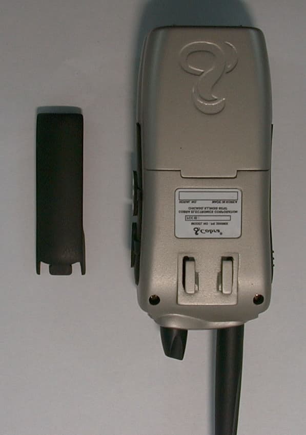
Click to zoom
Application Details
- Equipment Class
- TNF - Licensed Non-Broadcast Transmitter Held to Face
- Date of Grant
- Nov 30, 2000
- Application Purpose
- Original Equipment
- Date of Application
- Jul 06, 2000
- Equipment Note
- GMRS
- Frequency Range
- 462.55000000 - 462.72500000
- Country
- United States
Documents & Files
Document Text
Text extracted from the exhibit documents filed with the FCC. Open a document above to read the original.
Users Manual
1 How to Use Your Cobra Professional 2-Way Radio Features of This Product• UHF FM Frequencies • 10 Weather Channels • Weather Alert • No Air Time Fees • Up to 5 Mile Range • 15 GMRS Channels(7 shared FRS Channels) • 38 CTCSS Subchannels • LCD Function Display • Talk Confirmation Tone • Call/Ring Button • Auto Battery Saver Circuity • Auto Squelch • 10 Memory Locations • Memory Scan • Dual Watch • Channel and CTCSS Scan • Lock Key • Call Notification • Belt Clip • Rubberized Cabinet Grips ContentsFeatures ..................................................................................................1 The GMRS Story ..................................................................................A1 FCC WarningsIncluded Accessories Controls & Indicators .......................................................................A2 Our Thanks to You .............................................................................A3 Customer Support..........................................................................A3 Operating your microTalk Battery Installation.........................................................................2Turning On ........................................................................................3LCD Display.......................................................................................4Auto Battery Power Saver............................................................5Hi/Lo Power ......................................................................................5Select Main Channel (1-7) ...........................................................6Select CTCSS Subchannel (00-38) ............................................7Battery Low.......................................................................................9Talking To Another Party .............................................................10Talk Confirmation Tone ................................................................11Listening For Another Party .......................................................11Calling Another Party....................................................................12Auto Squelch....................................................................................14Maximum Range Extender .........................................................14 External Microphone/Speaker Jack .........................................15 Advanced Features ...........................................................................16 Listening to Weather Channels .................................................16Programming Memory Locations ............................................20Scan Function ..................................................................................26Memory Scan Function ................................................................29Tone Settings ...................................................................................31Lock Function ..................................................................................33Dual Watch........................................................................................34 microTalk Range ................................................................................37 Making Life Easier And Safer .......................................................38 Frequency Ranges .............................................................................40 Caring for Your microTalk .............................................................42 microTalk Professional Specifications ....................................43 Limited Two Year Warranty ...........................................................44 Optional Accessories .......................................................................45 Order Form ...........................................................................................46 If You Think You Need Service .....................................Back Cover Cobra PR 2000 manual M(4217)A 6/14/00 9:05 AM Page 1 2 3 Operation Operation NoteUse high quality “AA” batteries,such as alkaline, NiMH or Ni-Cad.Incorrect positioning can dam-age both the batteries and theunit.See Accessories on page 45.Charge ports are located onside of unit.NoteWhen batteries are low or needcharging the () BATT LOW indicator will blink.Replace alkaline batteries. BatteryInstallation Pull lock tab down and lift door up(towards you) toremove batterycover. Insert six “AA” bat- teries. Position bat-teries according topolarity markings. 2 1 Install Batteries NoteWhenever the unit is on, youcan receive communications.Turning OnYour microTalkProfessional Antenna Turning On Your microtalk ProfessionalTurn the Volume control clockwise to switchpower on. Set volume to desired level. Turn theVolume control counter-clockwise to turn power off.The radio is equippedwith a SMA female anten-na connector and amatching UHF antenna.Place top of unit withantenna on connector,turning clockwise untiltight. You can replace thisantenna with an optionalmobile antenna whenusing the radio inside acar, or a base antenna in afixed location.Antenna TURN KNOB CLOCKWISE PLACE ON CONNECTOR. TURN CLOCKWISE Cobra PR 2000 manual M(4217)A 6/14/00 9:05 AM Page 2 4 5 Operation Operation NoteThe Auto Battery Save Circuitdoes not effect the unit’s abilityto receive incoming transmissions. Auto Battery Power SaverYour microTalk Professional has a unique circuitdesigned to extend battery life. If there are notransmissions within 10 seconds, the unit willautomatically switch to mode. P. SAVER High/Low Power SwitchWhen in close proximity to other party, or duringclear weather conditions you can switch fromHigh to Low Power to extend battery life. The icon will flash. P. SAVER Auto BatteryPower SaverHigh/LowPower Switch Illuminatingthe Display Illuminating the DisplayPress and release MON Button to illuminate display for ten seconds. MON PTT MON PRESS AND RELEASE POWER SAVER Press & Release thelock button and itwill switch from High t…
Text truncated - open the document above for the full version.
Users Manual
1 How to Use Your Cobra P rofessional 2-Way Radio Features of This Product •UHF FM Frequencies •10 Weather Channels •Weather Alert •No Air Time Fees •Up to 5 Mile Range •15 GMRS Channels (7 shared FRS Channels) •38 CTCSS Subchannels •LCD Function Display •Talk Confirmation To n e •Ca l l / Ring Bu t to n •Au to Ba t te ry Saver Ci rc u i ty •Auto Squelch •10 Memory Locations •Memory Scan •Dual Watch •Channel and CTCSS Scan •Lock Key •Call No t i f i ca t i o n •Belt Clip •Rubberized Cabinet Grips Contents Features..................................................................................................1 The GMRS Story..................................................................................A1 FCC Warnings Included Accessories Controls & Indicators.......................................................................A2 Our Thanks to You.............................................................................A3 Customer Support..........................................................................A3 Operating your microTalk Battery Installation.........................................................................2 Turning On........................................................................................3 LCD Display.......................................................................................4 Auto Battery Power Saver............................................................5 Hi/Lo Power......................................................................................5 Select Main Channel (1-7)...........................................................6 Select CTCSS Subchannel (00-38)............................................7 Battery Low.......................................................................................9 Talking To Another Party.............................................................10 Talk Confirmation Tone................................................................11 Listening For Another Party.......................................................11 Calling Another Party....................................................................12 Auto Squelch....................................................................................14 Maximum Range Extender.........................................................14 External Microphone/Speaker Jack.........................................15 Advanced Features...........................................................................16 Listening to Weather Channels.................................................16 Programming Memory Locations............................................20 Scan Function..................................................................................26 Memory Scan Function................................................................29 Tone Settings...................................................................................31 Lock Function..................................................................................33 Dual Watch........................................................................................34 microTalk Range................................................................................37 Making Life Easier And Safer.......................................................38 Frequency Ranges.............................................................................40 Caring for Your microTalk .............................................................42 microTalk Professional Specifications....................................43 Limited Two Year Warranty...........................................................44 Optional Accessories.......................................................................45 Order Form...........................................................................................46 If You Think You Need Service.....................................Back Cover Cobra PR 2000 manual M(4217)A 8/17/00 2:18 PM Page 1 23 OperationOperation Note Use high quality “AA”batteries, such as alkaline,NiMH or Ni-Cad. Incorrect positioning can dam- age both the batteries and the unit. See Accessories on page 45. Charge ports are located on side of unit. Note When batteries are low or need charging the()BATT LOW indicator will blink. Replace alkaline batteries. Battery Installation Pull lock tab down and lift door up (towards you) to remove battery cover. Insertsix “AA”bat- teries. Position bat- teries according to po l a ri ty marki n g s. Install Batteries Note Wh e n ever the unit is on, yo u can re ce i ve co m m u n i ca t i o n s. Turning On Your microTalk Professional Antenna Turning On Your microtalk Professional Turn the Volume control clockwise to switch power on.Set volume to desired level.Turn the Volume control counter-clockwise to turn power off. The radio is equipped with a SMA female anten- na connector and a matching UHF antenna. Place top of unit with antenna on connector, turning clockwise until tight.You can replace this antenna with an optional mobile antenna when using the radio inside a car,or a base antenna in a fixed location. Antenna TURN KNOB CLOCKWISE PLACE ON CONNECTOR. TURN CLOCKWISE Cobra PR 2000 manual M(4217)A 8/17/00 2:18 PM Page 2 45 OperationOperation Note The Auto Battery Save Circuit does not effect the unit’s ability to receive incoming transmissions. Auto Battery Power Saver Your microTalk Professional has a unique circuit designed to extend battery life. If there are no transmissions within 10 seconds,the unit will automatically switch tomode. High/Low Power Switch When in close proximity to other party,or during clear weather conditions you can switch from High to Low Power to extend battery life. Theicon will flash. Auto Battery Power Saver High/Low Power Switch Illuminating the Display Illuminating the Display Press and releaseMON Button to illuminate display for ten seconds. PRESS AND RELEASE POWER SAVER Press & Release the lock button…
Text truncated - open the document above for the full version.
Internal Photos
P
Parts List/Tune Up Info
8. Αλιγνμεντ ινστρυχτιονσ WARNING Ανψ ρεπαιρσ ορ αδφυστμεντσ σηουλδ βε μαδε υνδερ τηε συπερπισιον οφ α θυαλιφιεδ ραδιοτελεπηονε τεχηνιχιαν. TRANSMITTER 1.Ποωερ Συππλψ ςολταγε Τηε Ποωερ συππλψ πολταγε σηουλδ βε σετ φορ 9.0ς∆Χ μεασυρεδ ατ τηε ραδιο δυρινγ τρανσμιτ. Περιοδιχαλλψ χηεχκ τηε ποωερ συππλψ πολταγε δυρινγ τηε αλιγνμεντ προχεδυρε. 2.Φρεθυενχψ Σεττινγ Α. Χοννεχτ α φρεθυενχψ χουντερ ορ Χομμυνιχατιονσ Σερπιχε Μονιτορ το τηε αντεννα χοννεχτορ τηρουγη αν ΡΦ ποωερ αττενυατορ (10 ωαττ μινιμυμ ρατινγ, 20 δΒ μινιμυμ αττενυατιον). Β. ∆επρεσσ τηε ΠΤΤ σωιτχη. Χ. Αδφυστ τηε ΧΤΞ1 τριμμερ χαπαχιτορ συχη τηατ τηε ουτπυτ φρεθυενχψ ισ εθυαλ το τηε χηαννελ φρεθυενχψ ωιτη α μαξιμυμ ερρορ οφ +/− 200 Ηζ. ∆. Ρελεασε τηε ΠΤΤ σωιτχη. 3. Ουτπυτ Ποωερ Αλιγνμεντ. Α. Σετ τηε ποωερ συππλψ πολταγε φορ 9.0ς∆Χ. Β. Χοννεχτ α Χομμυνιχατιονσ Σερπιχε Μονιτορ ορ α ωαττμετερ ανδ δυμμψ λοαδ το τηε αντεννα χοννεχτορ. Χ. ∆επρεσσ τηε ΠΤΤ σωιτχη. ∆. Το βε χονπινχεδ φορ 2.3(0.5) Ωαττ ουτπυτ ποωερ ωιτη α μαξιμυμ ερρορ οφ +/− 0.3(0.3−0.8) Ωαττ. Ε. Ρελεασε τηε ΠΤΤ σωιτχη. 4. ∆επιατιον Αδφυστμεντ. Α. Χοννεχτ αν αυδιο γενερατορ το τηε μιχροπηονε φαχκ θΙΓ. Τηε αυδιο φρεθυενχψ Σηουλδ βε σετ ατ 1 ΚΗζ. Β. Χοννεχτ αν ΦΜ δεπιατιον μετερ ορ Χομμυνιχατιονσ Σερπιχε Μονιτορ το τηε αντεννα χοννεχτορ τηρουγη αν ΡΦ ποωερ αττενυατορ (10 ωαττ μινιμυμ ρατινγ, 20 δΒ μινιμυμ αττενυατιον). Σετ τηε μονιτορ το ρεαδ πεακ δεπιατιον. Χ. ∆επρεσσ τηε ΠΤΤ σωιτχη. ∆. Αδφυστ τηε αυδιο γενερατορ λεπελ 100 μς ρμσ. Ε. Αδφυστ ΡςΜ1 φορ +/− 4.0 ΚΗζ μαξιμυμ δεπιατιον. (Ωιτη ΧΤΧΣΣ τονε) Φ. Το βε χονπινχεδ +/− 3.8ΚΗζ ωιτηουτ ΧΤΧΣΣ τονε.(2.0ΚΗζ δεπ. 20δΒ υπ) γ. Ρελεασε τηε ΠΤΤ σωιτχη.
RF Exposure Info
Re: FCC ID: BBOPR2000WX, EA98128 Correspondence Reference #15305/15306 Per your 7/28 email inquiry, response follows: (a) the type and number of antenna(s) to be used for this device and a detailed description of the antenna connector, if any. SUPPLIED ANTENNA IS A HELICALLY WOUND ELECTRICAL QUARTER WAVE. CONNECTOR IS A STANDARD "SMA" SERIES. RADIO IS FEMALE, ANTENNA HAS INTEGRAL MALE SMA. (b) maximum antenna gain for antenna(s) indicated in (a) GAIN FOR HELICALLY SHORTENED QUARTER WAVE IS TYPICALLY NO MORE THAN 1 dbi. (c) can this device sustain continuous operation with respect to its hardware capabilities and allowable operating functions ? THERE ARE NO TIMERS OR OTHER LIMITING DEVICES. CONTINUOUS TRANSMISSION IS POSSIBLE, BUT DEVICE IS PTT OPERATED AND HEAT-SINK LIMITED. (d) are there any other hardware or operating restrictions that could limit a person's RF exposure NO (e) is source-based time-averaging (see 2.1093 of rules) applicable to reduce the average output power ? DEVICE IS FM. POWER OUTPUT IS INVARIANT DURING KEYDOWN PERIODS. (f) this device has headset and belt-clip accessories that would allow body-worn operations, what is the minimum separation distance between the antenna and the user's body in this operating configuration ? WITH RADIO ON THE BELT CLIP, ANTENNA CENTER-LINE IS OFFSET 2.4 CM FROM BELT CLIP ATTACHMENT SURFACE. DISTANCE TO USER’S BODY IS A FUNCTION OF USER’S SHAPE. HEADSET OR REMOTE MIKE IS NOT A SUPPLIED ACCESSORY. (g) can this device access wire-line services to make phone calls, either directly or through an operator NO (h) can specific operating instructions be given to users to eliminate any potential RF exposure concerns for both front-of-the-face and body-worn operating configurations ? YES, DRAFT OF INSTRUCTIONS FOLLOW. (i) any other applicable information the applicant may provide that can serve as effective means for ensuring RF exposure compliance. NONE Safety Information For FRS UNIT Your wireless handheld portable transceiver contains a low power transmitter. When the PTT button is pushed it sends out radio frequency (RF) signals. The device is authorized to operate at a duty factor not to exceed 50%. In August 1996, the Federal Communications Commissions (FCC) adopted RF exposure guidelines with safety levels for hand-held wireless devices. Important: To maintain compliance with the FCC s RF exposure guidelines hold the transmitter at least 1 inch (2.5 centimeters) from your face and speak in a normal voice, with the antenna pointed up and away. If you wear the handset on your body while using the headset accessory, use only the (BRANDNAME) supplied belt clip for this product and ensure that the antenna is at least 1 inch (2.5 centimeters) from your body when transmitting. If the distance between the antenna and the body is LESS THAN 1.0”(2.5cm) DO NOT USE THIS DEVICE IN THE BODY WORN CONFIGURATION. Use only the supplied antenna. Unauthorized antennas, modifications, or attachments could damage the transmitter and may violate FCC regulations. Normal Position: Hold the transmitter approximately 1” from your face and speak in a normal voice, with the antenna pointed up and away.
RF Exposure Info
Re: FCC ID: BBOPR2000WX, EA98128 Correspondence Reference #15305/15306 Per your 7/28 email inquiry, response follows: 1.) Because this unit is used with a specific antenna provided with the unit, the tests for power output should be performed as radiated to determine ERP via the substitution method: ERP (d) based on substitution of a dipole: 1.89 W. 2.) Likewise, the tests for radiated spurious emissions should be performed with the unit operating with it’s normal antenna connected: Spurious emissions w/ short helical antenna: dBc 462.588 0 925.176 64V 1387.764 49V 1850.352 55V 2312.940 56V 2775.526 73H 3238.114 75H 3700.702 65H 4163.288 65H 4625.878 77H (a) the type and number of antenna(s) to be used for this device and a detailed description of the antenna connector, if any. SUPPLIED ANTENNA IS A HELICALLY WOUND ELECTRICAL QUARTER WAVE. CONNECTOR IS A STANDARD "SMA" SERIES. RADIO IS FEMALE, ANTENNA HAS INTEGRAL MALE SMA. (b) maximum antenna gain for antenna(s) indicated in (a) GAIN FOR HELICALLY SHORTENED QUARTER WAVE IS TYPICALLY NO MORE THAN 1 dbi. (c) can this device sustain continuous operation with respect to its hardware capabilities and allowable operating functions ? THERE ARE NO TIMERS OR OTHER LIMITING DEVICES. CONTINUOUS TRANSMISSION IS POSSIBLE, BUT DEVICE IS PTT OPERATED AND HEAT-SINK LIMITED. (d) are there any other hardware or operating restrictions that could limit a person's RF exposure NO (e) is source-based time-averaging (see 2.1093 of rules) applicable to reduce the average output power ? DEVICE IS FM. POWER OUTPUT IS INVARIANT DURING KEYDOWN PERIODS. (f) this device has headset and belt-clip accessories that would allow body-worn operations, what is the minimum separation distance between the antenna and the user's body in this operating configuration ? WITH RADIO ON THE BELT CLIP, ANTENNA CENTER-LINE IS OFFSET 2.4 CM FROM BELT CLIP ATTACHMENT SURFACE. DISTANCE TO USER’S BODY IS A FUNCTION OF USER’S SHAPE. HEADSET OR REMOTE MIKE IS NOT A SUPPLIED ACCESSORY. (g) can this device access wire-line services to make phone calls, either directly or through an operator NO (h) can specific operating instructions be given to users to eliminate any potential RF exposure concerns for both front-of-the-face and body-worn operating configurations ? YES, DRAFT OF INSTRUCTIONS FOLLOW. (i) any other applicable information the applicant may provide that can serve as effective means for ensuring RF exposure compliance. NONE Safety Information Your wireless handheld portable transceiver contains a low power transmitter. When the PTT button is pushed it sends out radio frequency (RF) signals. The device is authorized to operate at a duty factor not to exceed 50%. In August 1996, the Federal Communications Commissions (FCC) adopted RF exposure guidelines with safety levels for hand-held wireless devices. Important: To maintain compliance with the FCC s RF exposure guidelines hold the transmitter at least 1 inch (2.5 centimeters) from your face and speak in a normal voice, with the antenna pointed up and away. If you wear the handset on your body while using the headset accessory, use only the (BRANDNAME) supplied belt clip for this product and ensure that the antenna is at least 1 inch (2.5 centimeters) from your body when transmitting. If the distance between the antenna and the body is LESS THAN 1.0”(2.5cm) DO NOT USE THIS DEVICE IN THE BODY WORN CONFIGURATION. Use only the supplied antenna. Unauthorized antennas, modifications, or attachments could damage the transmitter and may violate FCC regulations. Normal Position: Hold the transmitter approximately 1” from your face and speak in a normal voice, with the antenna pointed up and away.
RF Exposure Info
Re: FCC ID: BBOPR2000WX; EA98128 Correspondence Reference Numbe r: 15645 Per FCC Inquiry Dated 08/17/00 2. Re vise d Use r Instructio ns will be submitte d thro ug h ADD ATTACHMENTS. See Ge ne ral Spe cifications (page 43), Battery Life listed at (1:1:18 ratio), our specification which works out to be same as your 5/5/90. 3. The follo wi ng CA UT IO N state me nt wi ll be i ncl ude d i n t he fina l use r i nstruct io ns to be locate d on t he inside front cover. ***CAUTION*** Important Safety Information for PR2000WX Your wireless handheld portable transceiver contains a radio frequency transmitter. When the PTT button is pushed it sends out RF signals. The device is authorized to operate at a duty factor not to exceed 50% to co mply wit h Fe de ra l Co mmu nicatio ns Co mmiss io n ( FCC) RF e xpos ure safety le ve l guide line s for ha nd- he ld wireless devices. To maintain compliance with the FCCs RF exposure guidelines hold the transmitter at least 2 inches (5 centimeters) from your face and speak in a normal voice, with the antenna pointed up and away. If you wear the transceiver on your body while using a headset or external microphone accessory, use only the supplied belt clip for this product and ensure that the antenna is at least 2 inches (5 centimeters) from your body when transmitting. If the distance between the antenna and the body is LESS THAN 2.0 INCHES (5cm) DO NOT TRANSMIT WITH THIS DEVICE IN THE BODY WORN CONFIGURATION. Unaut horiz e d ante nnas, modifications, or attachments could damage the transmitter and may violate FCC regulations. Normal Operating Position: Hold the transmitter approximately 2 to 3” from your face and speak in a normal voice, with the antenna pointed up and away.
RF Exposure Info
CAUTION Important Safety Information For PR2000WX Your wireless handheld portable transceiver contains a radio frequency transmitter. When the PTT button is pushed the transmitter sends out RF signals. The device is authorized to operate at a transmit duty factor not to exceed 5% to comply with Federal Communications Commissions (FCC) RF exposure safety level guidelines for hand-held wireless devices. To maintain compliance with the FCC’s RF exposure guidelines hold the transceiver at least 2 inches (5 centimeters) from your face and speak in a normal voice, with the antenna pointed up and away. If you wear the transceiver on your body while using a headset or external microphone accessory, use only the supplied belt clip for this product and ensure that the antenna is at least 2 inches (5 centimeters) from your body when transmitting. If the distance between the antenna and your body is less than 2.0 inches (5cm) do not transmit with this device in the body worn configuration . Unauthorized antennas, modifications, or attachments could damage the transceiver and may violate FCC regulations. Normal Operating Position: Hold the transceiver approximately 2 to 3" from your face with the antenna pointed up and away.
RF Exposure Info
Mr. Kwok Chan Re: Cobra Electronics Corporation FCC ID: BBOPR2000WX, EA98128 1. Battery Operation: Battery supply: 6 cells “AA” size Alkaline Manganese Dioxide Continuous transmit time to 1.1V per cell: High Power (2W) = 1 hour Low Power (0.5W) = 2 hours Depending on ambient temperature, on high power, thermal failure of the output device may occur before the 1 hour battery life limit is reached. “Key down to destruct” testing has not been done. 2. Revised Caution Statement: CAUTION Important Safety Information For PR2000WX Your wireless handheld portable transceiver contains a radio frequency transmitter. When the PTT button is pushed the transmitter sends out RF signals. The device is authorized to operate at a transmit duty factor not to exceed 5% using alkaline AA size batteries to comply with Federal Communications Commissions (FCC) RF exposure safety level guidelines for hand-held wireless devices. To maintain compliance with the FCC’s RF exposure guidelines hold the transceiver at least 2 inches (5 centimeters) from your face and speak in a normal voice, with the antenna pointed up and away. If you wear the transceiver on your body using the supplied belt clip, do not transmit with this device in the body worn configuration. Unauthorized antennas, modifications, or attachments could damage the transceiver and may violate FCC regulations. Normal Operating Position: Hold the transceiver approximately 2 inches to 3 inches from your face with the antenna pointed up and away.
Test Report
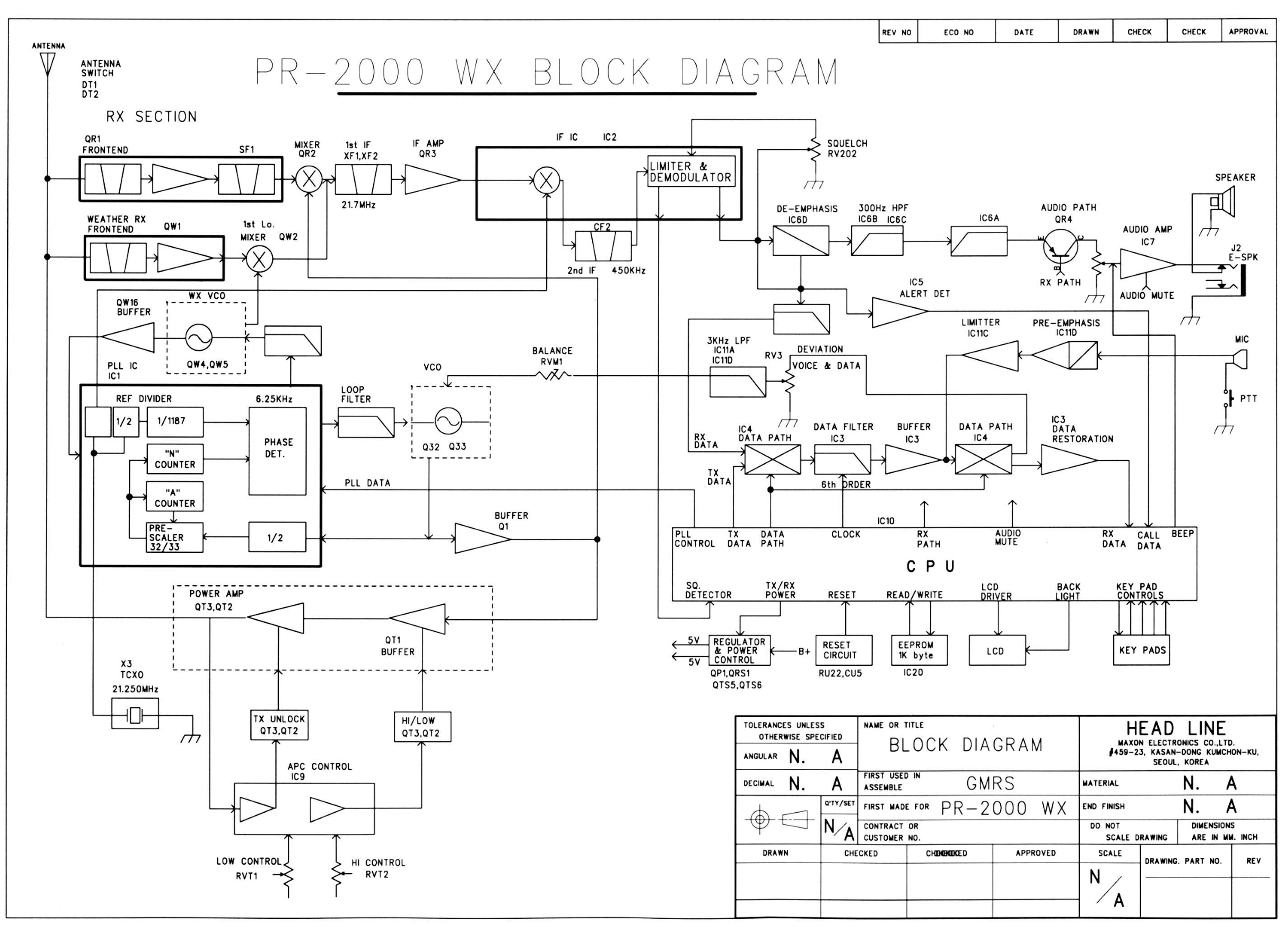
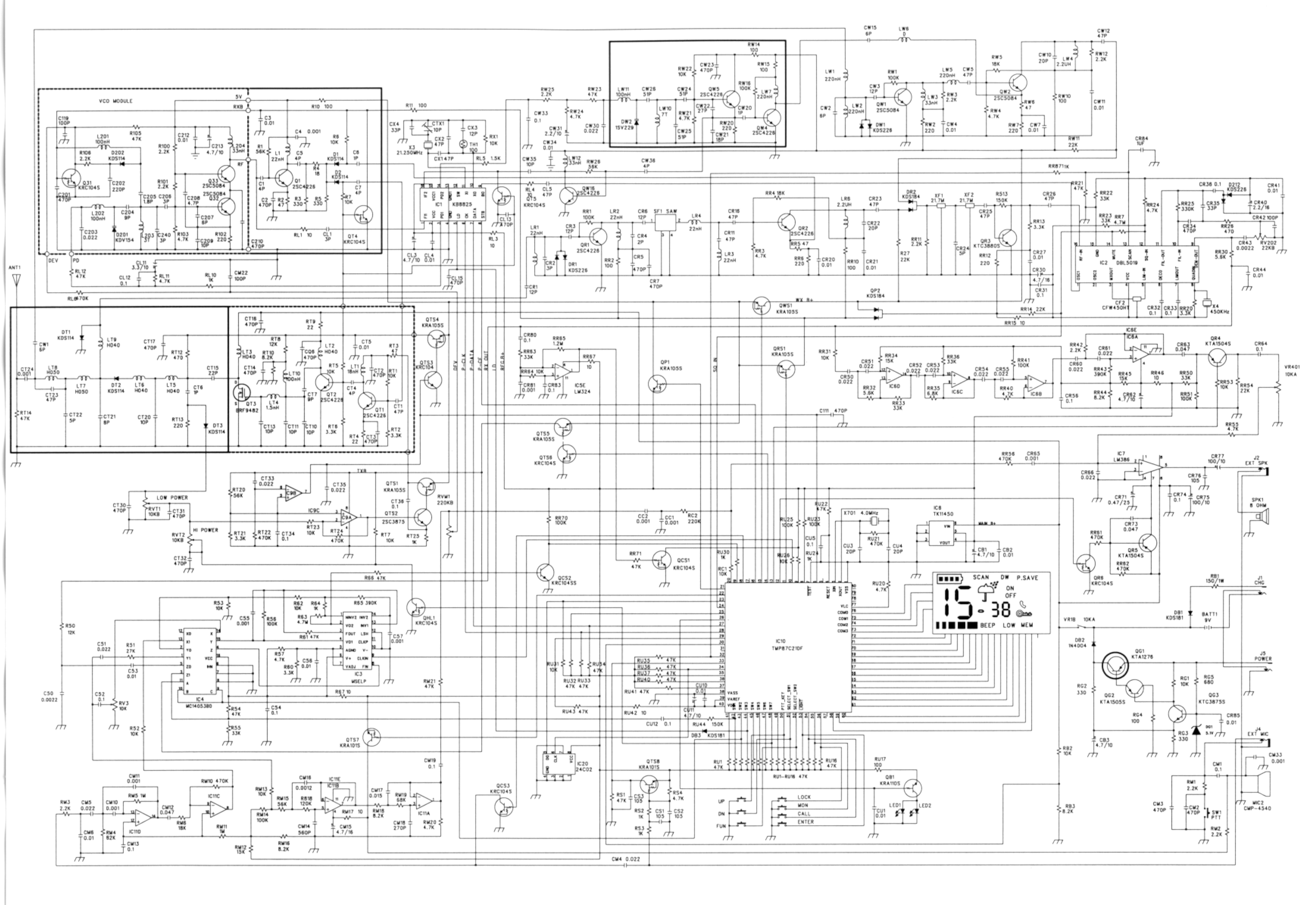
ENGINEERING STATEMENT For Certification of COBRA ELECTRONICS CORPORATION Model No. PR-2000WX FCC ID: BBOPR2000WX I am an Electronics Engineer, a principal in the firm of Hyak Laboratories, Inc., Springfield, Virginia. My education and experience are a matter of record with the Federal Communications Commission. Hyak Laboratories, Inc. has been authorized by Cobra Electronics Corporation to make certification measurements on the PR-2000WX transceiver. These tests were made by me or under my supervision in our Springfield laboratory. Test data and documentation required by the FCC for certification are included in this report. The data verifies that the above mentioned transceiver meets FCC requirements and certification is requested. _________________________ Rowland S. Johnson Dated: June 15, 2000 A. INTRODUCTION The following data are submitted in connection with this request for type acceptance of the PR-2000WX transceiver in accordance with Part 2, Subpart J of the FCC Rules. The PR-2000WX is a hand-held, battery operated, UHF, frequency modulated, 3 W transceiver intended for voice communications applications in the 462.5500 - 462.7250 MHz band under Part 95 in the GMRS service. B. GENERAL INFORMATION REQUIRED FOR TYPE ACCEPTANCE (Paragraph 2.983 of the Rules) 1. Name of applicant: Cobra Electronics Corporation 2. Identification of equipment: FCC ID: BBOPR2000WX a. The equipment identification label is submitted as a separate exhibit. b. Photographs of the equipment are submitted as separate exhibits. 3. Quantity production is planned. 4. Technical description: a. 16k0F3E emission b. Frequency range: 462.5500-462.7250 MHz. c. Operating power of transmitter is fixed at the factory at 3 watts. d. Maximum power permitted under FCC Part 95 (interstitial) is 5 watts ERP. The PR- 2000WX fully complied with that power limitation. d. The dc voltage and dc currents at final amplifier: Collector voltage: 8.9 Vdc Collector current: 0.55 A f. Function of each active semiconductor device: See Appendix 1. g. Complete circuit diagram is submitted as a separate exhibit. h. A draft instruction book is submitted as a separate exhibit. i. The transmitter tune-up procedure is submitted as a separate exhibit. 2 B. GENERAL INFORMATION (continuted) j. A description of circuits for stabilizing frequency is included in Appendix 2. k. A description of circuits and devices employed for suppression of spurious radiation and for limiting modulation is included in Appendix 2. l. Not applicable. 5. Data for 2.985 through 2.997 follow this section. C. RF POWER OUTPUT (Paragraph 2.985(a) of the Rules) RF power output was measured with a Bird 4421 RF power meter and a Narda 765-20 attenuator as a 50 ohm dummy load. Maximum power was 2.6 watts. (The transmitter was tuned by the factory.) D. MODULATION CHARACTERISTICS 1. A curve showing frequency response of the transmitter is shown in Figure 1. Reference level was audio signal output from a Boonton 8220 modulation meter with one kHz deviation. Audio output was measured with an Audio Precision System One TRMS voltmeter and tracking generator. 2. Modulation limiting curves are shown in Figure 2, using a Boonton 8220 modulation meter. Signal level was established with an Audio Precision System One. The curves show compliance with paragraphs 2.987(b) and 95.633(b). 3. Figure 3 is a graph of the post-limiter low pass filter which meets the requirements of paragraph 95.633(b) in providing a roll-off of 60Logf/3 dB where f is audio frequency in kHz. Measurements were made following EIA RS-152B with an Audio Precision System One on the Boonton 8220 modulation meter audio output. 4. Occupied_Bandwidth (Paragraphs 2.989(c), 90.209(b)(4), and 95.629(a) of the Rules) Figure 4 is a plot of the sideband envelope of the transmitter output taken with a Tektronix 494P spectrum analyzer. Modulation corresponded to conditions of 2.989(c)(1) and consisted of 2500 Hz. 3 C. MODULATION CHARACTERISTICS (continued) tone at an input level 16 dB greater than that necessary to produce 50% modulation at 2149 Hz, the frequency of maximum response. Measured modulation under these conditions was 3.2 kHz. The plot is within the limits imposed by Paragraph 90.211(h) for frequency modulation. The horizontal scale (frequency) is 10 kHz per division and the vertical scale (amplitude) is a logarithmic presentation equal to 10 dB per division. 5. Emission Designator Calculation: (2D + 2F) 2x5.0 + 2x3.0 = 16k0F3E 4 FIGURE 1 MODULATION FREQUENCY RESPONSE MODULATION FREQUENCY RESPONSE FCC ID: BBOPR2000WX FIGURE 1 5 FIGURE 2 AUDIO LIMITER CHARACTERISTICS AUDIO LIMITER CHARACTERISTICS FCC ID: BBOPR2000WX FIGURE 2 6 FIGURE 3 AUDIO LOW PASS FILTER RESPONSE AUDIO LOW PASS FILTER RESPONSE FCC ID: BBOPR2000WX FIGURE 3 7 FIGURE 4 OCCUPIED BANDWIDTH ATTENUATION IN dB BELOW MEAN OUTPUT POWER Required On any frequency more than 50% up to and including 100% of the 25 authorized bandwidth, 20 kHz (10-20 kHz) On any frequency more than 100%, up to and i…
Text truncated - open the document above for the full version.
Contact Information
Applicant
Chris de Waal(Senior Project Engineer)
Technical Contact
Hyak Laboratories, Inc.Rowland S Johnson
[email protected](703) 451-1188
7011 Calamo St., Suite 107 · Springfield, Virginia · United States
Non-Technical Contact
Hyak Laboratories, Inc.Georgia Hall
[email protected](703) 451-1188
Test Firm
Hyak Laboratories, Inc.Rowland Johnson
703-451-1188
Technical Specifications
| # | Rule Parts | Frequency Range | Power Output | Emission | Tolerance |
|---|---|---|---|---|---|
| 1 | 95A | 462.55 MHz - 462.725 MHz | 1.89 W | 16K0F3E | 0.0005000000 % |
Other Applications from Cobra Electronics Corporation
BBOCHEM01
Jul 21, 2026Radar detector
Equipment Class
CRD - Part 15 Radar DetectorBBOPERF600
Jul 13, 2026PERFORMA 600 RADIO DIGITAL BULK, US/COBRA PERFORMA 600 DIGITAL SINGLE PACK, US/COBRA PERFORMA 600 DIGITAL SIX PACK, US/COBRA PERFORMA 600 DIGITAL RADIO, US
Equipment Class
TNF - Licensed Non-Broadcast Transmitter Held to Face
BBOBB650
May 01, 2026VHF Marine Radio Transceiver
Equipment Class
TNF - Licensed Non-Broadcast Transmitter Held to FaceBBOLESS01
Apr 14, 2026Radar detector with Bluetooth
Equipment Class
DTS - Digital Transmission System
BBOCBPT01
Feb 14, 2023Wireless PTT
Equipment Class
DTS - Digital Transmission System