BBOPR300022 CH FRS/ GMRS Transceiver - Transmitter Portion
Cobra Electronics Corporation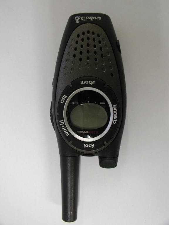
Click to zoom
Application Details
- Equipment Class
- FRF - Part 95 Family Radio Face Held Transmitter
- Date of Grant
- Jan 12, 2003
- Application Purpose
- Original Equipment
- Date of Application
- Jan 12, 2003
- Equipment Note
- 22 CH FRS/ GMRS Transceiver - Transmitter Portion
- Frequency Range
- 462.56250000 - 467.71250000
- Country
- United States
Documents & Files
Document Text
Text extracted from the exhibit documents filed with the FCC. Open a document above to read the original.
Users Manual
2 English Making Life Easier & Safer Owner’s Manual NothingComes Close To A Cobra ™ English 2-WAYRADIO MODEL PR3000 DX Printed in Philippines Part No. 480-049-P Owner’s Manual Nadase compara a Cobra ™ Español PR3000 DX Printed in Philippines Part No. 480-049-P Introduction Staying in touch with your family and friends is convenient and easy when using your microTALK ® radio. Some of the many uses you will discover include: Communicating with others while hiking, biking, and working; keeping track of family and friends at a crowded public event; checking with travel companions in another car; talking with neighbors; arranging meeting spots with others while shopping at the mall. Secure your microTALK ® radio while on the go. Carrying your microTALK ® radio with you is easy when using the belt clip or wrist strap. The belt clip easily attaches to your belt, purse, or backpack. Simply squeeze the clip and place it where you prefer. For Assistance In the U.S.A. In this user’s manual, you should find all the information you need to operate your microTALK ® radio. If you require further assistance after reading this manual, Cobra ® Electronics offers the following customer assistance services: Automated Help Desk English only. 24 hours a day, 7 days a week 773-889-3087 (phone). Customer Assistance Operators English and Spanish. 8:00 a.m. to 6:00 p.m. CT, Monday through Friday (except holidays) 773-889-3087 (phone). Questions English and Spanish. Faxes can be received at 773-622-2269 (fax). Technical Assistance English only. www.cobra.com (on-line: Frequently Asked Questions). English and Spanish. productinfo @cobra.com (e-mail). For Assistance Outside the U.S.A. Contact Your Local Dealer Belt Clip Wrist Strap Customer Assistance ©2002 Cobra ® Electronics Corporation 6500 West Cortland Street Chicago, Illinois 60707 USA www.cobra.com RADIO BIDIRECCIONAL MODEL 2 Español Una vida más sencilla y segura Introducción Es muy fácil y práctico mantenerse en contacto con su familia y sus amigos cuando utiliza un radio microTALK ® .Usted descubrirá gran número de aplicaciones para el radio, como las siguientes: comunicación con otras personas en excursiones, paseos el bicicleta o en el trabajo; contacto con la familia y los amigos en concurridos eventos públicos, comunicación con compañeros de viaje en otro automóvil; conversaciones con los vecinos; ponerse de acuerdo en un punto de reunión durante una visita al centro comercial. Transporte el radio microTALK ® con seguridad. Es muy fácil transportar el radio microTALK ® con la pinza para cinturón o la correa para la muñeca. La pinza se sujeta fácilmente al cinturón, un bolso o una mochila. Sólo tiene que oprimir la pinza y colocarla donde quiera. Ayuda en los EE.UU. En este manual para el usuario encontrará toda la información necesaria para usar el radio microTALK ® . Si después de leer este manual requiere ayuda adicional, Cobra ® Electronics ofrece los siguientes servicios de apoyo a clientes: Centro automatizado de ayuda Únicamente inglés. Disponible las 24 horas del día, todos los días del año, llamando por teléfono al 773-889-3087. Operadores de ayuda al cliente Inglés y español. Disponibles de 8:00 a.m. a 6:00 p.m., hora del centro de EE.UU., de lunes a viernes (excepto días festivos), llamando por teléfono al 773-889-3087. Preguntas Inglés y español. Puede enviar sus preguntas por fax al 773-622-2269. Ayuda técnica Únicamente inglés. www.cobra.com (en Internet: preguntas más frecuentes). Inglés y español. Corre electrónico: [email protected] Ayuda fuera de los EE.UU. Comuníquese con un distribuidor de productos Cobra ® de su localidad. ©2002 Cobra ® Electronics Corporation 6500 West Cortland Street Chicago, Illinois 60707 USA www.cobra.com Pinza para el cinturón Correa para la muñeca Ayuda a clientes Battery Compartment Battery Door Latch Belt Clip Wrist Strap Connector OperationCustomer AssistanceWarranty 5 Nothing comes close to a Cobra ™ Introduction 4 English Product Features 3 English Product Features Introduction Backlit LCD Display Channel Up/Down Buttons Speaker/ Microphone Call Button Mode Button Antenna Key Lock Button Hi•Low Power Button External Speaker/ Microphone Jack Light/ Max Range Button Talk Button On/Off Volume Knob Charger Jack Introduction Backlit LCD Display Important FCC Licensing Information This radio operates on General Mobile Radio Service (GMRS) frequencies which require a Federal Communications Commission (FCC) license. See page 18 for licensing and other related information. Receive/ Transmit To w e r Icon Hi•Low Power Icon Lock Icon Keystroke Tones Icon Call Tones and VibrAlert ™ Icon Roger Beep Icon Signal Strength Meter Icon Battery Level Indicator Main Channel Numbers Power Saver Icon CTCSS Privacy Code Numbers Scan Icon Vox Icon Features • Two-Way Radio with up to a six (6) mile (10 km) range • 22 Channels (7 shared with FRS/GMRS, 7 FRS only, 8 GMRS only) • 38 PRIVACY Codes • Hands-Free Operation (VOX) • VibrAlert ® Silent Paging • Signal Strength Meter • Scan (channel, privacy code) • Selectable Hi•Low Power (in GMRS) • Backlit LCD Display • Call Alert (10 selectable tones) • Lock • Speaker/ Microphone Jack • “Roger Beep” (selectable On/Off) • Battery/Power Saver • Keystroke Tones (selectable On/Off) • Auto Squelch • Maximum Range Extender •Belt Clip • Wrist Strap Caring for Your microTALK ® Radio • Your microTALK ® radio will give you years of trouble-free service if cared for properly. Handle the radio gently. Keep the radio away from dust. Never put the radio in water or in a damp place. Avoid exposure to extreme temperatures. Batteries • To Install or Replace Batteries: 1. Remove belt clip by releasing belt clip latch and sliding clip up. 2. Pull down on the Battery Door Latchto remove the battery compartment cover. 3. Insert four (4) AAA batteries. (Always use high quality alkaline batteries.) Position batteries according to polarity markings. 4. Replace Battery Compartment cover and belt clip. Conta…
Text truncated - open the document above for the full version.
Cover Letter(s)
COBRA ELECTRONICS CORPORATION FCC ID: BBOPR3000 REF: CORRESPONDENCE ID #: 6905 T:\C\COBRA\1220UT2\oet 6905\Cobraelectronics 2003 fcc response.doc Timco Engineering Inc. 849 NW State Road 45 Newberry FL 32669 From: Mario de Aranzeta To: Martin Perrine [email protected] FCC Equipment Authorization Branch Re: FCC ID: BBOPR3000 Applicant: Cobra Electronics Corporation Correspondence Reference Number: 6905 731 Confirmation Number: TC868999 Subject: Request for additional information 1) Clarification of setup for occupied BW measurements. Please justify reference level and apparent conducted power of 73.7 dBuV. User manual and SAR report suggest 2 W. Also, please provide data for both GMRS and FRS modes. The reference level in the OBW plot is arbitrary and in no way is should be used as a reference to anything except the CW plot. The RF is sampled to a level that keeps it on the scale of the analyzer and maintained at that level from CW to Occupied. Conducted power is not provided as the UUT has a permanently attached antenna. The output power measured by TEI was ERP not conducted. A block diagram of the test setup is included on the next page. Occupied bandwidth of the GMRS and FRS is identical. The manufacturer makes no distinction in modulation limiting or audio frequency response and therefore occupied bandwidth between the services are the same. The test reports will now have two necessary bandwidth calculations even though they are identical. 2) Measurement details of conducted spurious emissions testing. Please provide measurement BW and detector type. This device is required to have a fixed, permanently attached antenna; therefore conducted spurious emissions testing is not required. 3) Details of radiated spurious testing. Please provide bandwidths and detector types. Confirm that the substitution method was used. Provide full measurement data and example calculations. Provide photograph of full test setup with and without substitution antenna in place. Provide new test data if substitution was not used. Pages 12 and 13 of our test report show details of spurious radiated emissions done via the substitution method. Our method closely follows that of TIA 603. A peak detector and appropriate bandwidths of the analyzer were used. Enclosed on pages 4 and 5 please find the details on radiated spurious emissions and substitution method. COBRA ELECTRONICS CORPORATION FCC ID: BBOPR3000 REF: CORRESPONDENCE ID #: 6905 T:\C\COBRA\1220UT2\oet 6905\Cobraelectronics 2003 fcc response.doc 4) Tune-up procedure, block diagram and parts lists. This information is supplied in a separate exhibit. COBRA ELECTRONICS CORPORATION FCC ID: BBOPR3000 REF: CORRESPONDENCE ID #: 6905 T:\C\COBRA\1220UT2\oet 6905\Cobraelectronics 2003 fcc response.doc The antenna of the EUT is coupled to the spectrum analyzer and to the modulation analyzer with a near field probe. COBRA ELECTRONICS CORPORATION FCC ID: BBOPR3000 REF: CORRESPONDENCE ID #: 6905 T:\C\COBRA\1220UT2\oet 6905\Cobraelectronics 2003 fcc response.doc TEST DATA (GMRS): Emission Frequency MHz Field Strength dBuV/m Generator Level Coax Loss Gain Relative to a dipole dB below carrier dBm Margin dB 462.70 126.20 29.5 0.5 0 0.00 29 0.00 925.40 73.4 -22.2 1.0 2.85 53 -24 11 1,388.20 72 -21.5 1.1 4.60 54 -25 12 1,850.90 75 -18.0 1.15 5.10 51 -22 9 2,313.70 73 -18.8 1.25 6.50 53 -24 11 2,776.40 69 -22.3 1.30 7.00 57 -28 15 3,239.10 77 -14.0 1.35 7.30 49 -20 7 3,701.90 71 -20.3 1.45 7.20 55 -26 13 4,164.60 63 -28.2 1.45 7.20 63 -34 21 4,627.40 69 -34.6 1.50 8.15 57 -28 15 Sample calculation for substitution method: Signal gen. (dBm) – coax loss (dB) + dipole difference (dB) = (dBm) TEST DATA (FRS): Emission Frequency MHz Field Strength dBuV/m Generator Level Coax Loss Gain Relative to a dipole dB below carrier dBm Margin dB 467.50 122.50 25.7 0.5 0 0.00 25.2 0.00 935.10 74 -22.2 1.0 2.85 49 -24 10.8 1,402.70 72 -29.5 1.1 4.60 51 -26 12.8 1,870.30 79 -23.0 1.15 5.10 44 -19 5.8 2,337.90 73 -30.3 1.25 6.50 50 -25 11.8 2,805.40 67 -36.7 1.30 7.00 56 -31 17.8 3,273.00 73 -31.0 1.35 7.30 50 -25 11.8 3,740.60 69 -34.7 1.45 7.20 54 -29 15.8 4,208.20 64 -39.7 1.45 7.20 59 -34 20.8 4,675.80 63 -41.6 1.50 8.15 60 -35 21.8 Sample calculation for substitution method: Signal gen. (dBm) – coax loss (dB) + dipole difference (dB) = (dBm) COBRA ELECTRONICS CORPORATION FCC ID: BBOPR3000 REF: CORRESPONDENCE ID #: 6905 T:\C\COBRA\1220UT2\oet 6905\Cobraelectronics 2003 fcc response.doc
Operational Description
7.THEORY OF OPERATION Circuit Compositions and Operation Theory The basic explanation for the circuit composition the two board controlling the analog circuit parts and the digital circuit parts. Receiver Transmission parts are composed in the double conversion system, which has the 1st IF Frequency of 21.7 MHz and 2nd IF Frequency of 450 kHz. With the saw filter, which has an excellent band characteristic and sharp characteristic, the 2 poles MCF used in the 1st IF, and the sensitivity repression is reduced for the more stable reception. RF Frontend The signal received by the antenna will be transmitted to the band pass filter through the antenna switching circuit consisted of LT1,LR1, CT1, CT2 and CT3. The front RF amplifier transistor QR1 consists of the saw filter and input/output band pass filter. Saw filter has the bandwidth of approximately 4 MHz, primarily diminishes the other signal rather then the 1st IF image and other signal within the reception band and amplifies only the necessary signal within the RF. 1st Mixer The receiver signal which has been amplified in the RF fronted is provided to the base of the 1st mixer QR2. The 1st L/O signal provide from the VCO is supplied to the emitter of QR2 and converted to the 1st IF 21.7 MHz. 1st IF Filter and 1st IF Amplifier The signal coverted by QR2 to 21.7 MHz, the 1st frequency, change its impedance through CR8, LR6 and then is infused to the fundamental MCF which has the center frequency of 21.7 MHz and the width of +/-3.75 kHz. Here, the signal reduces the image and other unwanted signal for the 2nd IF. Then the signal is infused to the IC3. The IC3 which functions as the 2nd mixer, the 2nd IF amplifier, and the FM detector,RSSI,PREMIC,compander,PLL circuit. 2nd Mixer, and IF, FM Detector The receiver IF signal of 21.7 MHz, which has been infused to IC3 is mixed with the 2nd L/O signal of 21.250MHz, and converted to 450 kHz, the 2nd IF frequency. The receiver signal converted to the 2nd IF frequency passed through the F3, the ceramic filter of 450 kHz again. After the limiting inside the IC11 and the FM demodulating by the quadrature detector inside the IC3, the signal offers the output through the 21th pin of IC3. The 2nd L/O signal of 21.250MHz, which infused to the IC3 filters and uses directly the crystal of 21.250 MHz. The squelch circuit is composed to detect the noised from the received signal demodulate in the 31th pin of the IC3. For this purpose, the noise filter is using the OP amplifier inside the IC3. Transmitter The transmission parts of the PR-3000 are designed to amplify the RF signal oscillated and modulated by the synthesizer to approximately 2(0.5) W by the power transistor of QT3. TX Power (QT3) The transmitted signal of approximately 2(0.5)W, combined at the driver TR is supplied to the base of the QT3 amplifier. The transmitted signal amplified to 2W here passes the TX LPF of the 2nd characteristic of the LT2 and the LT3, and RX/TX switching takes place by the DT1. After this, the signal is provided to the antenna the TX LPF of the 1st characteristics, consisted of the LT1. Frequency Synthesizer Voltage Control Oscillator (VCO) The VCO of oscillates 462.5625 MHz to 462.7250 MHz under the transmission condition and 440.8620 MHz to 441.025 MHz under the reception condition. The VCO consists of the clap oscillator of the QV1, and contains the oscillator frequency of approximately 21.7MHz during the transmission/reception conversion. That is since the VCO should oscillate relatively low frequency during reception compared to transmission, the DV2 is directly biased by the QV2. Therefore as a result, the CV8 is added in parallel to the resonance circuit of the VCO to oscillate a low frequency. During transmission, a relatively high frequency should be oscillating compared to reception. Therefore, the DV2 is adversely biased by the QV2, and as a result, the CV8, which is added unparallel to the circuit of the VCO is removed to oscillate the desired transmission frequency. PLL Part of the IC3 controls the VCO in order to oscillate the accurate frequency. The output frequency of the VCO is supplied to the 44 th pin of IC3. At the IC3, TCXO(21.250MHz) by the TCXO-1 is compared to the output frequency of the VCO. The VCO is controlled the loop filter consisted of the RM32,RM33,RM34, and the CM14, in order to oscillate the stable frequency wanted for the radio. The VCO controlled voltage which has passed the loop filter is supplies to the DV1 varactor diode, and the VCO an oscillate the PLL programmed frequency by the capacity variation in the DV1. In addition, the LV2 on the VCO circuit function as frequency for the VCO to be properly controlled. RX/TX Buffer Amplifier (QB1) The RF signal oscillate at the VCO is provide to the QR2 RX 1st mixer through the QB1 during the reception, and is provide to the QT2 power driver amplifier through the QT1 during the transmission. PLL Frequency Synthesizer (AN 6311) The PLL synthesizer of the signal loop PLL circuit with the reference of 6.25 kHz. The IC3 includes all the function such as the reference oscillator, the driver, the phase detector, the lock detector, and the programmable divider. At the reference oscillator, the 21.250 MHz TCXO of the TCXO is connected to the pin 52,53 of the IC3 to oscillate the frequency of 21.250MHz. The TCXO (21.250MHz) is the temperature compensation circuit to maintain the frequency within the allowable error range even under a low temperature of -20 . The phase detector sends out the output power to the loop filter through 44 pin of the IC3. IF the oscillation frequency of the VCO is low compared to the referenced frequency, the phase detector sends out the output power in positive pulse. If the oscillation frequency of the VCO is high, phase detector send out can maintain the frequency set. The programmable divider maintains the desired frequency with control from the CPU. The dividing ratio, "N" to oscillate the desired frequency is as belo…
Text truncated - open the document above for the full version.
Parts List/Tune Up Info
9. SEMICONDUCTORS AND FUNCTIONS ) QR1 2SC4226 N.E.C RX AMP QR2 2SC4226 N.E.C RX MIXER QS1 KRA105S K.E.C RX B+ QS2 KRA105S K.E.C POWER SAVE QS3 KRA110S K.E.C LED CONTROL QS4 KRA105S K.E.C TX B+ QS5 KTC3875 K.E.C TX POWER CONTROL QS6 KRA105S K.E.C PTT KEY SWITCHING QS7 KRA105S K.E.C MAIN POWER SWITCHING QS8 KRC104S K.E.C AUDIO MUTE QS9 KTA1504 K.E.C AUDIO MUTE QS10 KTA1504 K.E.C AUDIO PATH QS11 KRC104S K.E.C CTCSS SWITCHING QV1 2SC4226 N.E.C OSCILLATOR QV2 KRC104S K.E.C TX/RX SWITCHING QB1 2SC4226 N.E.C VCO BUFFER QB2 KRC104S K.E.C TX/RX SWITCHING QT1 2SC4226 N.E.C TX BUFFER QT2 2SC4226 N.E.C TX DRIVE AMP QT3 NE5510279A N.E.C TX MAIN AMP ) IC3 AN6311FA MATSUSHITA PLL,MIXER,IF PROSSING IC1 IL 324F INTERGRAL CTCSS TONE DET.(300Hz LPF) IC2 IL 324F INTERGRAL AUDIO 300Hz HPF IC7 IL 386 INTERGRAL AUDIO POWER AMP IC10 IL 358 INTERGRAL AUDIO POWER AMP IC5 TK71540 TOKO REGULATOR IC3 TMP86PM29AU TOSHIBA CPU @ N.E.C : NATIONAL SEMICONDUCTOR @ AUK : AUK CORP. @ ELM : ELM TECHNOLOGY @ K.E.C : KOREA ELECTRONICS CO.,LTD.
Parts List/Tune Up Info
8. Alignment instructions WARNING Any repairs or adjustments should be made under the supervision of a qualified radiotelephone technician. TRANSMITTER 1.Power Supply Voltage The Power supply voltage should be set for 6.0VDC measured at the radio during transmit. Periodically check the power supply voltage during the alignment procedure. 2.Frequency Setting A. Connect a frequency counter or Communications Service Monitor to the antenna through an RF power attenuator (10 watt minimum rating, 20 dB minimum attenuation). B. Depress the PTT switch. C. Adjust the CTX1 trimmer capacitor such that the output frequency is equal to the channel frequency with a maximum error of +/- 200 Hz. D. Release the PTT switch. 3. Output Power Alignment. A. Set the power supply voltage for 6.0VDC. B. Connect a Communications Service Monitor or a wattmeter and dummy load to the antenna connector. C. Depress the PTT switch. D. To be convinced for 2.0(0.5) Watt output power with a maximum error of +/- 0.5(0.4-0.8) Watt. E. Release the PTT switch. 4. Deviation Adjustment. A. Connect an audio generator to the microphone jack JIG. The audio frequency Should be set at 1 KHz. B. Connect an FM deviation meter or Communications Service Monitor to the antenna connector through an RF power attenuator (10 watt minimum rating, 20 dB minimum attenuation). Set the monitor to read peak deviation. C. Depress the PTT switch. D. Adjust the audio generator level 100 mV rms. E. Adjust VR4 for +/- 2.2 KHz maximum deviation. (With CTCSS tone) F. To be convinced +/- 1.8KHz without CTCSS tone.(1.5KHz dev. 20dB up) g. Release the PTT switch. RECEIVER NOTE: Insure that the proper channel has been selected before preceding with the alignment procedure. 1. Power Supply Voltage The proper voltage for testing is 6.0 VDC. 2. Receiver Alignment A. Connect an RF signal generator or Communications Service Monitor to the antenna connector. B. Connect a SINAD meter and oscilloscope across the speaker terminals. C. Set the output level of the RF signal generator for -47 dBm. The generator should be set for +/- 1.5 KHz deviation of a 1 KHz tone. D. Set the audio output level for 0.6 Vrms. by adjusting volume. E. Reduce the output level of the RF signal generator for produce a 6-12 dB SINAD indication.
Test Report
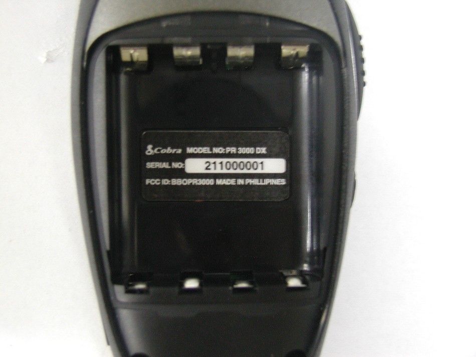
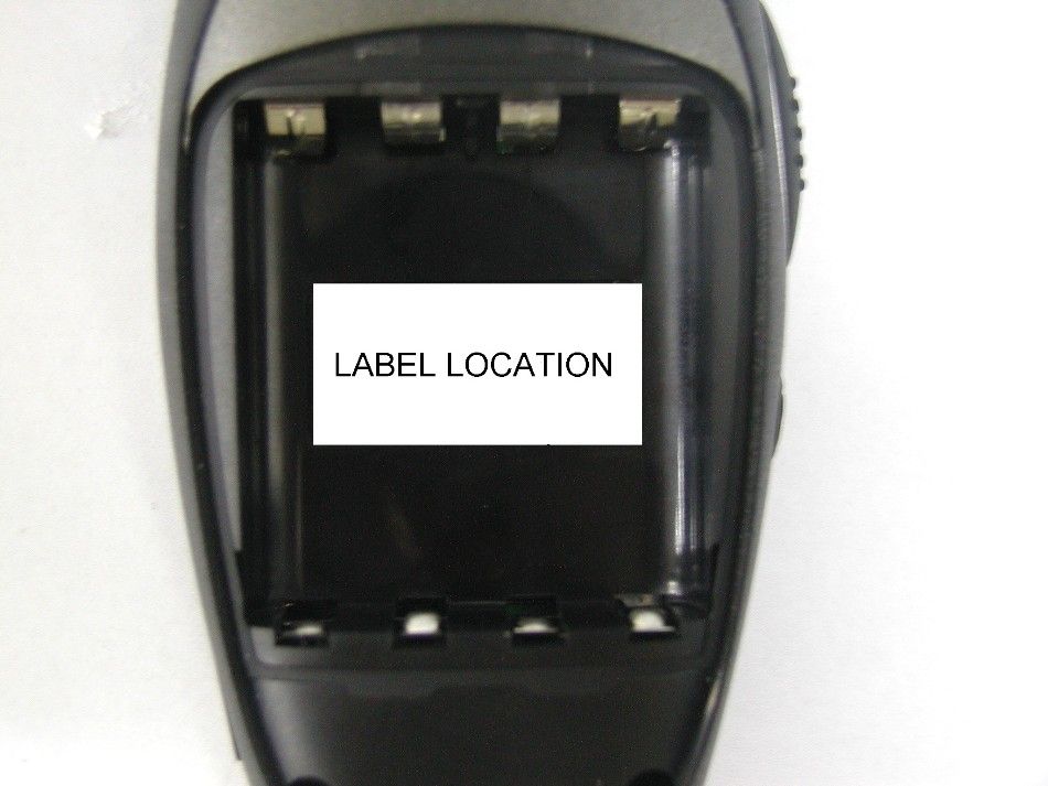
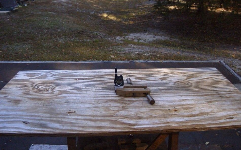
APPLICANT: COBRA ELECTRONICS CORPORATION FCC ID: BBOPR3000 REPORT #: C\COBRA\1220UT2\1220UT2TestReport.doc TABLE OF CONTENTS TABLE OF CONTENTS LIST APPLICANT: COBRA ELECTRONICS CORPORATION FCC ID: BBOPR3000 TEST REPORT: PAGE 1......COVER SHEET - GENERAL INFORMATION & TECHNICAL DESCR. PAGE 2......TECHNICAL DESCRIPTION CONTINUED & RF POWER OUTPUT PAGE 3......MODULATION CHARACTERISTICS & AUDIO FREQUENCY RESPONSE GRAPH PAGE 4......MODULATION LIMITING GRAPH – 300 Hz & 1000 Hz PAGE 5......MODULATION LIMITING GRAPH – 2500 Hz PAGE 6......AUDIO LOW PASS FILTER GRAPH PAGE 7......OCCUPIED BANDWIDTH PAGE 8......OCCUPIED BANDWIDTH PLOT PAGE 9......OCCUPIED BANDWIDTH PLOT - CW PAGE 10.....SPURIOUS EMISSIONS AT ANTENNA TERMINALS PAGE 11.....UNWANTED RADIATION – GMRS PAGE 12.....UNWANTED RADIATION - FRS PAGE 13.....METHOD OF MEASURING RADIATED SPURIOUS EMISSIONS PAGE 14.....FREQUENCY STABILITY PAGE 15-17..LIST OF TEST EQUIPMENT EXHIBITS CONTAINING: EXHIBIT 1.........FCC ID LABEL SAMPLE EXHIBIT 2.........LABEL LOCATION EXHIBIT 3.........EXTERNAL PHOTOGRAPHS EXHIBIT 4.........INTERNAL PHOTOGRAPHS EXHIBIT 5.........BLOCK DIAGRAM EXHIBIT 6.........SCHEMATICS EXHIBIT 7.........USER'S MANUAL EXHIBIT 8.........THEORY OF OPERATION EXHIBIT 9.........ALIGNMENT PROCEDURE EXHIBIT 10........PARTS LIST EXHIBIT 11........TEST SET UP PHOTO APPLICANT: COBRA ELECTRONICS CORPORATION FCC ID: BBOPR3000 REPORT #: C\COBRA\1220UT2\1220UT2TestReport.doc Page 1 of 17 GENERAL INFORMATION REQUIRED FOR CERTIFICATION 2.1033(c)(1)(2) COBRA ELECTRONICS CORPORATION will manufacture the FCCID: BBOPR3000 GMRS/FRS COMBINATION TRANSCEIVER in quantity, for use under FCC RULES PART 95. COBRA ELECTRONICS CORPORATION 6500 WEST CORTLAND STREET CHICAGO, IL 60707 2.1033 (c) TECHNICAL DESCRIPTION 2.1033(c)(3) Instruction book. A draft copy of the instruction manual is included as EXHIBIT 7. 2.1033(c) (4) Type of Emission: 10K5F3E 95.631 Bn = 2M + 2DK M = 3000 D = 2.25K Bn = 2(3000)+2(2250) = 10.5K GMRS Authorized Bandwidth 20.0 kHz 2.1033(c)(5) GMRS Frequency Range: 1. 462.5500 13. 462.7000 95.621 2. 462.5625 14. 462.7125 3. 462.5750 15. 462.7250 4. 462.5875 16. 467.5500 5. 462.6000 17. 467.5750 6. 462.6125 18. 467.6000 7. 462.6250 19. 467.6250 8. 462.6375 20. 467.6500 9. 462.6500 21. 467.6750 10. 462.6625 22. 467.7000 11. 462.6750 23. 467.7250 12. 462.6875 FRS Authorized Bandwidth 12.5 kHz 2.1033(c)(5) FRS Frequency Range: 1. 462.5625 8. 467.5625 95.627 2. 462.5875 9. 467.5875 3. 462.6125 10. 467.6125 4. 462.6375 11. 467.6375 5. 462.6625 12. 467.6625 6. 462.6875 13. 467.6875 7. 462.7125 14. 467.7125 MHz 2.10311c)(6)(7) RF power is measured by the substitution method as 2.1046(a) outlined in TIA/EIA - 603. With a nominal battery voltage of 6.0 V, and the transmitter properly adjusted the RF output measures: GMRS - .8 Watts FRS - .33 Watts APPLICANT: COBRA ELECTRONICS CORPORATION FCC ID: BBOPR3000 REPORT #: C\COBRA\1220UT2\1220UT2TestReport.doc Page 2 of 17 2.1033(c)(6)(7) Power Output shall not exceed 0.50 Watts effective 95.639 radiated power. Power will automatically switch for 95.640 GMRS or FRS operation. 2.1033(c)(8) DC Voltages and Current into Final Amplifier: FINAL AMPLIFIER ONLY FOR LOW POWER SETTING INPUT POWER: (6.0V)(.210A) = 1.26 Watts FOR HIGH POWER SETTING INPUT POWER: (6.0V)(.600A) =3.60 Watts 2.1033(c)(9) Tune-up procedure. The tune-up procedure is included as EXHIBIT # 9. 2.1033(c)(10) Complete Circuit Diagrams: The circuit diagram is included as EXHIBIT 6 of this report. The block diagrams are included as EXHIBIT 5 of this report. 2.1033(c)(11) A photograph or a drawing of the equipment identification label is included as exhibit No. 1. 2.1033(c)(12) Photographs(8"X10") of the equipment of sufficient clarity to reveal equipment construction and layout, including meters, labels for controls, including any view under shields. See exhibits 3-4. 2.1033(c)(13) Digital modulation is not allowed. 2.1033(c)(14) The data required by 2.1046 through 2.1057 is submitted below. 2.1046(a) RF power output. The test procedure used was TIA/EIA-603 S2 APPLICANT: COBRA ELECTRONICS CORPORATION FCC ID: BBOPR3000 REPORT #: C\COBRA\1220UT2\1220UT2TestReport.doc Page 3 of 17 APPLICANT: COBRA ELECTRONICS CORPORATION FCC ID: BBOPR3000 REPORT #: C\COBRA\1220UT2\1220UT2TestReport.doc Page 4 of 17 2.1047(a)(b) Modulation characteristics: AUDIO FREQUENCY RESPONSE The audio frequency response was measured in ac- cordance with TIA/EIA Specification 603. The audio frequency response curve is shown below. The audio signal was fed into a dummy microphone circuit and into the microphone connector. The input required to produce 30 percent modulation level was measured. See plot below. Audio Frequency Response -30 -25 -20 -15 -10 -5 0 5 100100010000 Frequency Hz Attenuation dB 2.1047(b) Audio input versus modulation The audio input level needed for a particular per- percentage of modulation was measured in accor- dance with TIA/EIA Specification 603. The audio input curves versus modulation are on the following pages. Curves are provided for audio input frequen- cies of 300, 1000, and 2500 Hz. APPLICANT: COBRA ELECTRONICS CORPORATION FCC ID: BBOPR3000 REPORT #: C\COBRA\1220UT2\1220UT2TestReport.doc Page 5 of 17 MODULATION LIMITING PLOT – 300 Hz 0 0.5 1 1.5 2 2.5 -90-80-70-60-50-40-30-20-10010 dBm Deviation 300Hz MODULATION LIMITING PLOT – 1000 Hz 0 0.5 1 1.5 2 2.5 -90-80-70-60-50-40-30-20-10010 dBm Deviation 1000Hz APPLICANT: COBRA ELECTRONICS CORPORATION FCC ID: BBOPR3000 REPORT #: C\COBRA\1220UT2\1220UT2TestReport.doc Page 6 of 17 MODULATION LIMITING PLOT – 2500 Hz 0 0.5 1 1.5 2 2.5 -90-80-70-60-50-40-30-20-10010 dBm Deviation 2500Hz APPLICANT: COBRA ELECTRONICS CORPORATION FCC ID: BBOPR3000 REPORT #: C\COBRA\1220UT2\1220UT2TestReport.doc Page 7 of 17 95.637 Post Limiter Filter Each GMRS transmitter, except a mobile station transmitter with a power of 2.5 Watts or less, must be equipped with an audio low pass filter. At any frequency between 3 & 20 kHz the filter …
Text truncated - open the document above for the full version.
Test Report
Test Report S/N: 112802-319BBO Test Date(s): December 20, 2002 FCC SAR Evaluation © 2002 Celltech Research Inc.1 of 21 Celltech Research Inc. declares under its sole responsibility that this device was found to be in compliance with the Specific Absorption Rate (SAR) RF exposure requirements specified in FCC 47 CFR §2.1093. The device was tested in accordance with the measurement standards and procedures specified in FCC OET Bulletin 65, Supplement C, Edition 01-01 (General Population / Uncontrolled Exposure). I attest to the accuracy of data. All measurements were performed by me or were made under my supervision and are correct to the best of my knowledge and belief. I assume full responsibility for the completeness of these measurements and vouch for the qualifications of all persons taking them. This test report shall not be reproduced partially, or in full, without the prior written approval of Celltech Research Inc. The results and statements contained in this report pertain only to the device(s) evaluated. Russell W. Pipe Senior Compliance Technologist Celltech Research Inc. DECLARATION OF COMPLIANCE SAR EVALUATION Test Lab CELLTECH RESEARCH INC. Testing and Engineering Lab 1955 Moss Court Kelowna, B.C. Canada V1Y 9L3 Phone: 250-448-7047 Fax: 250-448-7046 e-mail: [email protected] web site: www.celltechlabs.com Applicant Information COBRA ELECTRONICS CORPORATION 6500 West Cortland Street Chicago, IL 60707 Rule Part(s):FCC 47 CFR §2.1093 Test Procedure(s):FCC OET Bulletin 65, Supplement C (01-01) Device Type:Portable UHF GMRS/FRS PTT Radio Transceiver FCC ID:BBOPR3000 Model(s):PR-3000 Modulation:FM (UHF) Tx Frequency Range(s):462.5500 - 462.7250 MHz (GMRS Channels 15-22) 462.5625 - 462.7125 MHz (FRS/GMRS Channels 1-7) 467.5625 - 467.7125 MHz (FRS Channels 8-14) RF Output Power Tested:2.0 Watts Conducted (GMRS) No. of Channels:22 Antenna Type(s):Fixed Battery Type(s):1.5V AAA Alkaline (x4) Body-Worn Accessories:Belt-Clip, Lapel Ear-Microphone Max. SAR Measured:0.635 W/kg - Face-held (100% duty cycle) 1.04 W/kg - Body-worn (100% duty cycle) Test Report S/N: 112802-319BBO Test Date(s): December 20, 2002 FCC SAR Evaluation © 2002 Celltech Research Inc.2 of 21 TABLE OF CONTENTS 1.0INTRODUCTION..................................................................... 3 2.0DESCRIPTION OF DUT............................................................ 3 3.0SAR MEASUREMENT SYSTEM ............................................... 4 4.0MEASUREMENT SUMMARY..................................................... 5 5.0DETAILS OF SAR EVALUATION............................................... 6 6.0EVALUATION PROCEDURES................................................... 6-7 7.0SYSTEM PERFORMANCE CHECK............................................ 8 8.0SIMULATED TISSUES............................................................. 9 9.0SAR LIMITS........................................................................... 9 10.0SYSTEM SPECIFICATIONS...................................................... 10 11.0PROBE SPECIFICATION......................................................... 11 12.0SAM PHANTOM...................................................................... 11 13.0LARGE PLANAR PHANTOM..................................................... 11 14.0DEVICE HOLDER.................................................................... 11 15.0TEST EQUIPMENT LIST........................................................... 12 16.0MEASUREMENT UNCERTAINTIES............................................ 13 17.0REFERENCES.......................................................................14 APPENDIX A - SAR MEASUREMENT DATA.............................................15 APPENDIX B - SYSTEM CHECK DATA....................................................16 APPENDIX C - SYSTEM VALIDATION.....................................................17 APPENDIX D - PROBE CALIBRATION....................................................18 APPENDIX E - MEASURED FLUID DIELECTRIC PARAMETERS................19 APPENDIX F - SAM PHANTOM CERTIFICATE OF CONFORMITY..............20 APPENDIX G - SAR TEST SETUP & DUT PHOTOGRAPHS........................21 Test Report S/N: 112802-319BBO Test Date(s): December 20, 2002…
Text truncated - open the document above for the full version.
Contact Information
Applicant
Chris de Waal(Senior Project Engineer)
Test Firm
Timco Engineering, Inc.Sid Sanders
Technical Specifications
| # | Rule Parts | Frequency Range | Power Output | Emission | Tolerance |
|---|---|---|---|---|---|
| 2 | 95B | 462.5625 MHz - 467.7125 MHz | 330.00 mW | 10K5F3E | 2.5 ppm |
Other Applications from Cobra Electronics Corporation
BBOCHEM01
Jul 21, 2026Radar detector
Equipment Class
CRD - Part 15 Radar DetectorBBOPERF600
Jul 13, 2026PERFORMA 600 RADIO DIGITAL BULK, US/COBRA PERFORMA 600 DIGITAL SINGLE PACK, US/COBRA PERFORMA 600 DIGITAL SIX PACK, US/COBRA PERFORMA 600 DIGITAL RADIO, US
Equipment Class
TNF - Licensed Non-Broadcast Transmitter Held to Face
BBOBB650
May 01, 2026VHF Marine Radio Transceiver
Equipment Class
TNF - Licensed Non-Broadcast Transmitter Held to FaceBBOLESS01
Apr 14, 2026Radar detector with Bluetooth
Equipment Class
DTS - Digital Transmission System
BBOCBPT01
Feb 14, 2023Wireless PTT
Equipment Class
DTS - Digital Transmission System