BBOPR330CFRS/GMRS Transceiver
Cobra Electronics Corporation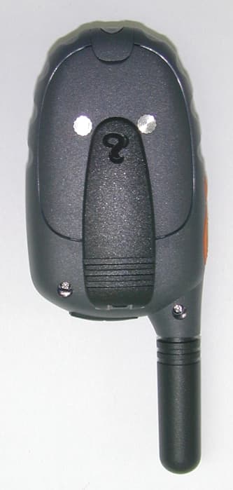
Click to zoom
Application Details
- Equipment Class
- FRF - Part 95 Family Radio Face Held Transmitter
- Date of Grant
- Jul 10, 2002
- Application Purpose
- Original Equipment
- Date of Application
- May 20, 2002
- Equipment Note
- FRS/GMRS Transceiver
- Frequency Range
- 467.56250000 - 467.71250000
- Country
- United States
Documents & Files
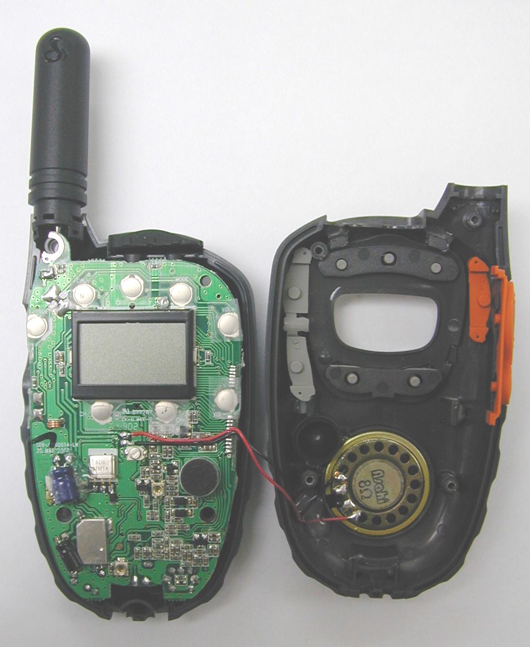
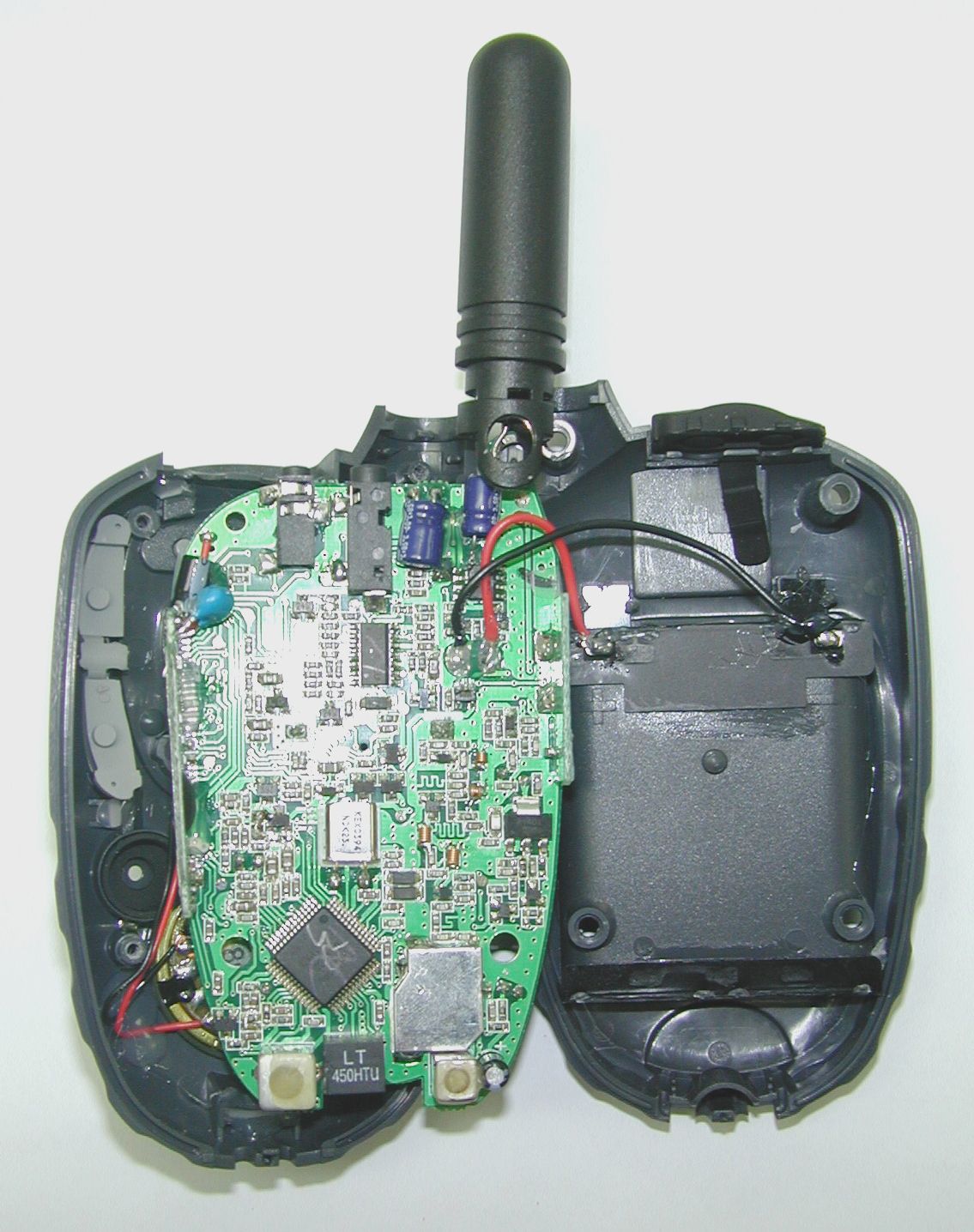
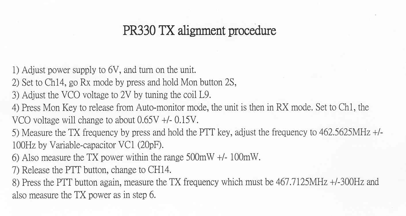
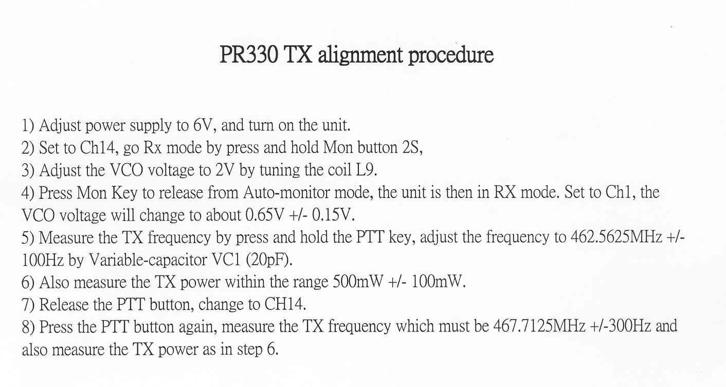
Document Text
Text extracted from the exhibit documents filed with the FCC. Open a document above to read the original.
Users Manual
FPO Operating Instructions for Your Cobra® microTALK® 2-WAY RADIO MODEL PR 330 Instrucciones de uso del RADIO BIDIRECCIONAL MODELO PR 330 Cobra® microTALK® Nothingcomes close to a Cobra ™ Nadase compara a Cobra ™ English, pages 1-16 Español, páginas 17-30 Product Features • TWO-WAY RADIO with up to a 2 mile (3 km) range • 22 CHANNELS • 38 CTCSS PRIVACY CODES • UHF FM frequencies • BACKLIT LCD display • EXTERNAL SPEAKER/MICROPHONE jack • 10 MEMORY LOCATIONS • FULL CHANNEL/CTCSS SCAN • MEMORY SCAN • DUAL WATCH • MAXIMUM RANGE extender • 5 CALL SIGNAL SELECTIONS • VOX MODE for hands-free transmissions • selectable "ROGER BEEP" confirmation tone • selectable KEYSTROKE TONES • AUTO SQUELCH • CALL ALERT • BATTERY SAVER circuitry • LOCK button • BELT CLIP • WRIST STRAP • WATER RESISTANT Installing or Replacing Batteries 1.Pull down the LOCK tab to remove the battery compartment cover. 2.Insert four AAA batteries. (Always use high quality alkaline batteries.) Position batteries according to polarity markings. (NOTE: See page 16 for information about optional battery pack and desktop charger accessories.) PRODUCT FEATURES ENGLISH 1 OPERATION ENGLISH 2 ON-OFF/ POWER button backlit LCD display LOCK button MODE button VOLUME UP & DOWN buttons CHANNEL SELECT buttons speaker/ microphone belt clip CALL button TALK button LIGHT/MAX RANGE button Antenna Lock tab battery compartment battery charger pads LOCK tab external speaker/ microphone jack LIGHT/MAX RANGE button TALK button Important FCC Licensing Information The PR 330 radio operates on General Mobile Radio Service (GMRS) frequencies which require a Federal Communications Commission (FCC) license. See page 15 for licensing and additional information. BACKLIT LCD DISPLAY receive/transmit tower icon CTCSS Privacy Code numbers memory location memory icon vox icon key lock icon roger beep icon keystroke tones icon Dual Watch icon power saver icon battery level meter main channel numbers feature on/off icons scan icon OPERATION Selecting a CTCSS Privacy Code CTCSS (Continous Tone Coded Squelch System) is an advanced tone coding system allowing you to select one of 38 privacy codes to reduce interference from other users on the channel. (NOTE:If you are using a privacy code, both radios must be tuned to the same channel and privacy code to communicate. Each channel will remember the last privacy code you selected.) To select a privacy code: 1.After selecting a main channel, press and release the MODE button. A small number will flash next to the channel in the LCD. 2.Push the CHANNEL SELECT button up or down to select a privacy code. You can hold the button up or down for fast advance. 3. When your desired privacy code is displayed, press and release the LOCK button or press the MODE button to enter selection and go to the next function. Calling Another Person To alert another person that you are calling: 1.Press and release the CALL button. The other person will hear a 2-second ringing tone. You cannot send or receive transmissions during the 2-second call tone. (See page 13 for instructions on how to select between 5 call tone settings.) OPERATION ENGLISH 4 CALL button MODE button CHANNEL UP CHANNEL DOWN Turning On Your microTALK ® Radio 1.Press and hold the ON/OFF POWER button for 2 seconds. A series of audible tones will indicate the radio is on. 2.Your microTALK ® is now in Standby mode, ready to receive transmissions. The radio is always in Standby mode except when the TALK, CALL, or MODE buttons are pressed. (For Advanced Features accessed through the MODE button, see page 7.) Illuminating the Display 1.Press and release the LIGHT/MAX RANGE button to illuminate the display for 10 seconds. Battery Indicator When only one segment of the battery indicator is blinking, the battery power is low and you should recharge your battery pack or change your AAA alkaline batteries. Auto Battery Save Your microTALK ® radio has a unique circuit designed to extend battery life. If there are no transmissions within 10 seconds, the unit will automatically switch to Battery Save mode and POWER SAVER will appear in the display. This will not affect the unit’s ability to receive incoming transmissions. Selecting a Channel 1.With the radio on, select any of the 22 channels by pushing the CHANNEL UP or CHANNEL DOWN button. (NOTE:Both radios must be tuned to the same channel to communicate.) ENGLISH 3 ON-OFF/POWER button LIGHT/MAX RANGE button CHANNEL UP CHANNEL DOWN MODE button LOCK button OPERATION Using the Lock Function The Lock function locks the CHANNEL, MODE, and POWER buttons to prevent accidental operation. To use the Lock function: 1.While in Standby mode, press and hold the LOCK button for one second. The Lock icon will be visible when the unit is locked. Buttons that are NOT locked are the CALL, VOLUME, LIGHT/MAX RANGE, and TALK buttons, which are all fully functional while the unit is locked. 2.To “unlock” buttons, press and release the LOCK button again. The Lock icon disappears and all buttons will be unlocked. External Speaker/ Microphone Jack Your microTALK ® radio can be fitted with an external speaker/microphone,freeing your hands for other tasks. See page 16 for optional accessories. To attach an external speaker/microphone: 1.Open the SPKR/MIC tab on top of the unit. 2.Insert the plug into the SPKR/MIC jack. Using the MODE button The MODE button allows you to use and program the various functions of your microTALK ® radio. If you press and hold the MODE button, the LCD will cycle through the different functions. OPERATION ENGLISH 6 external microphone speaker speaker/microphone jack LOCK button MODE button Talking to Another Person 1.Press and hold the TALK button. 2.With the microphone about 2 inches (5 cm) from your mouth, speak in a normal voice. 3. Release the button when you’re finished talking and listen for a response. You cannot receive incoming calls while pressing the TALK button. “Roger Beep” Confirmation Tone Your listener will hear an au…
Text truncated - open the document above for the full version.
Test Report
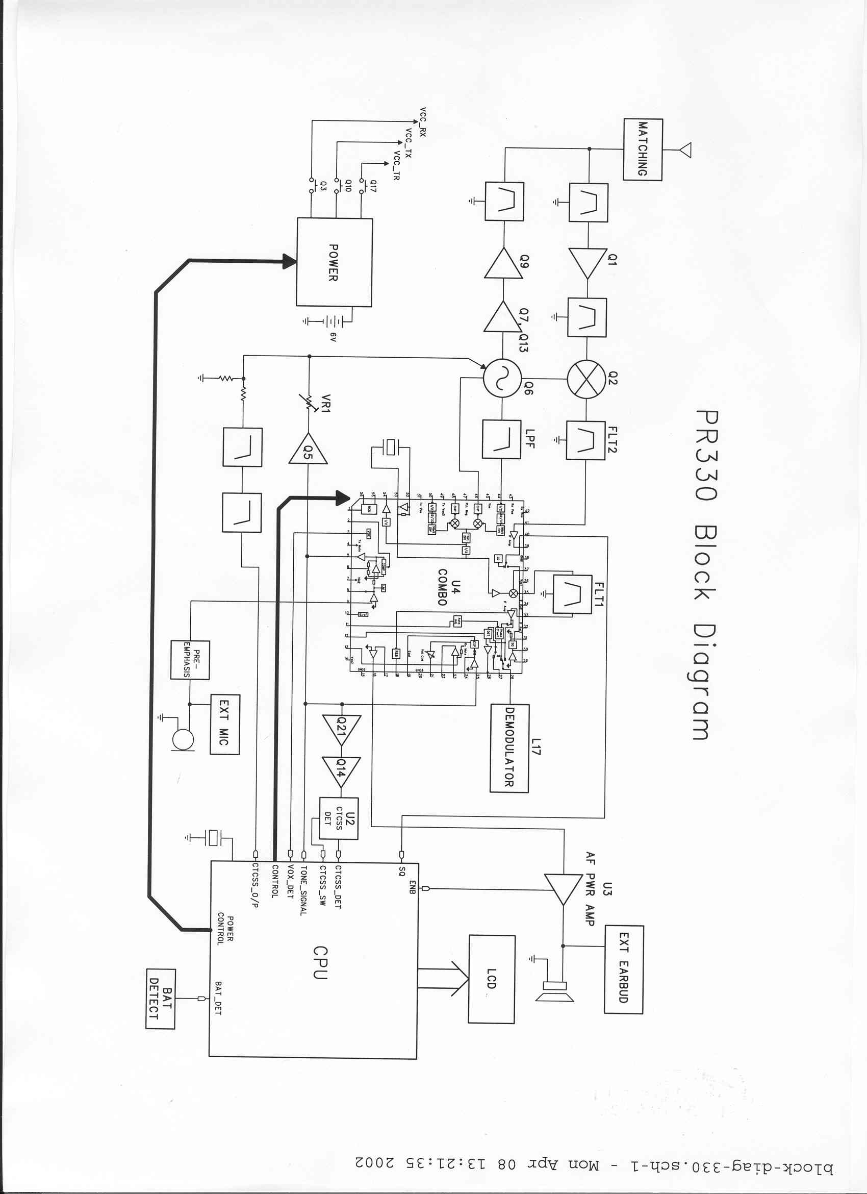
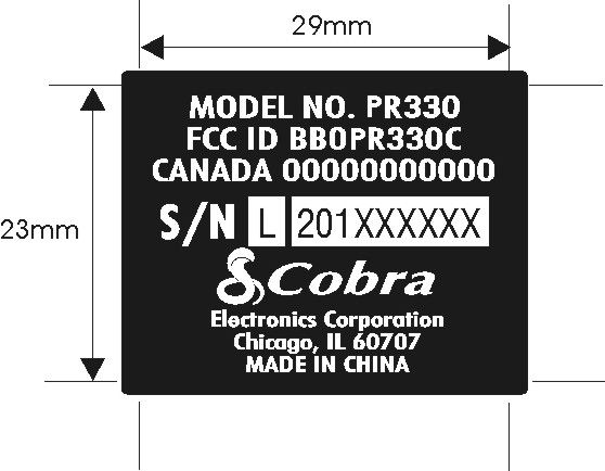
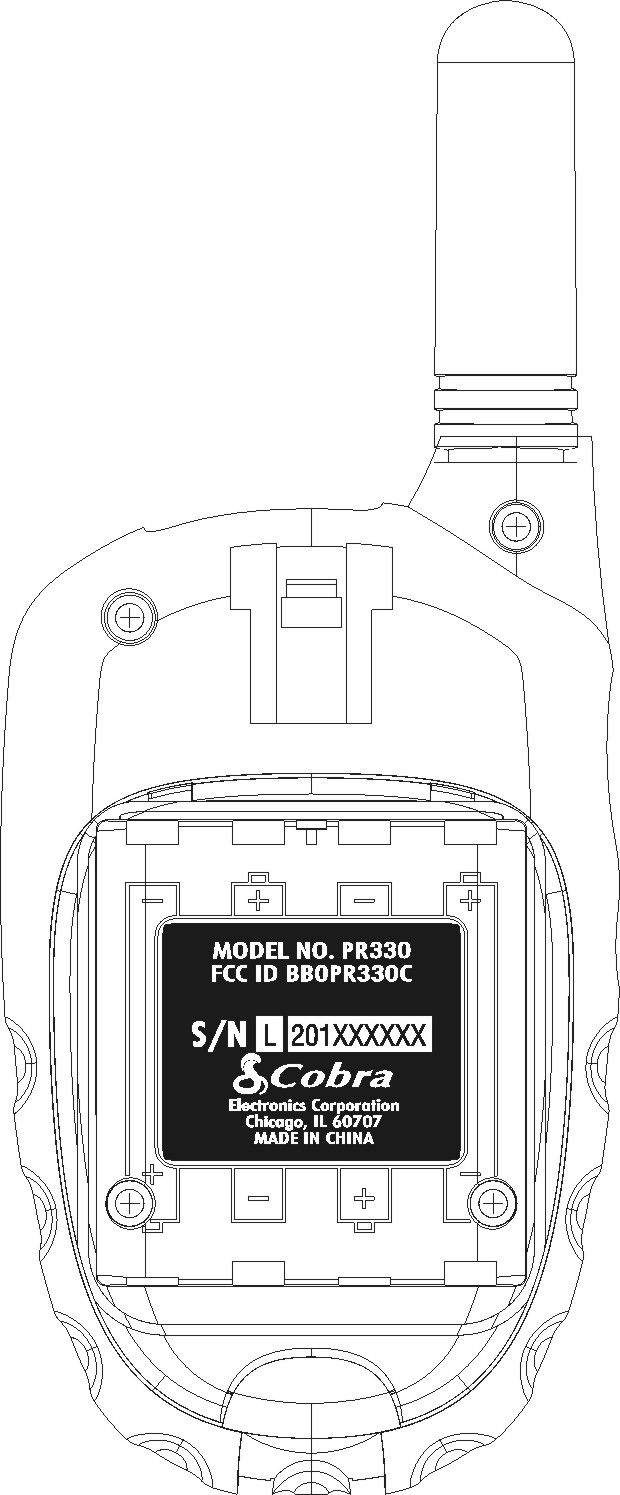
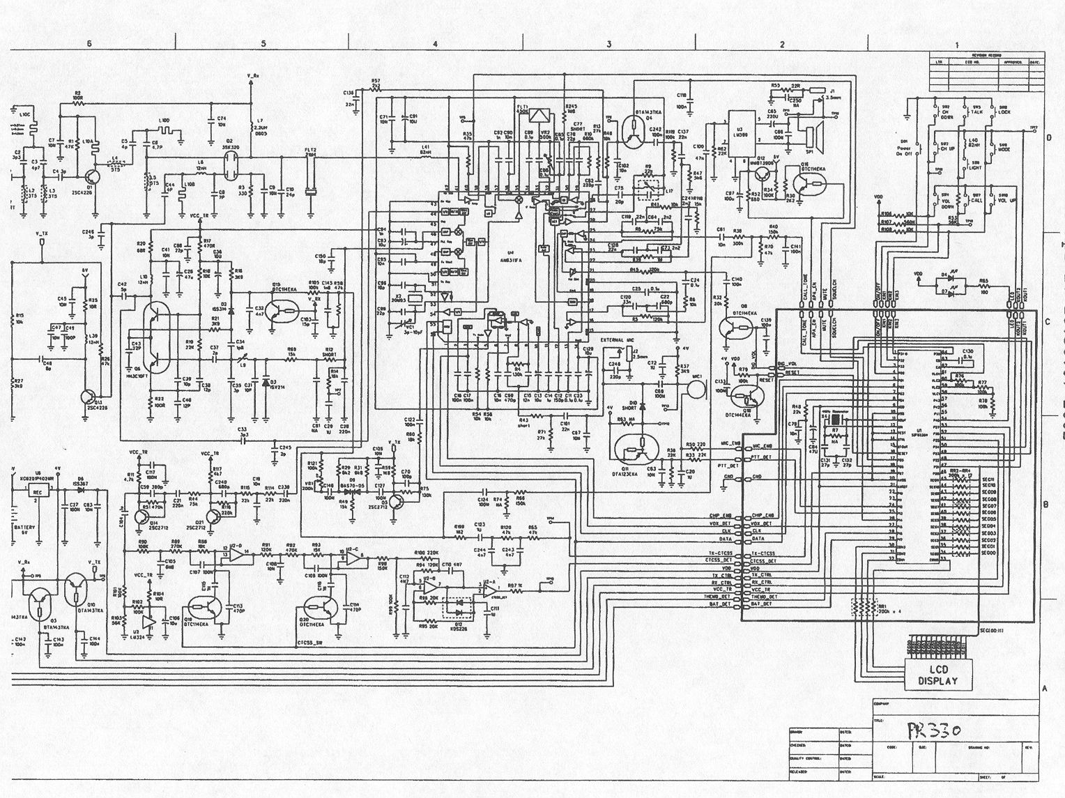
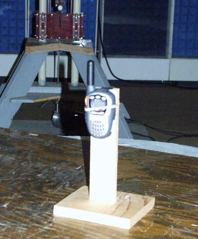
A. INTRODUCTION The following data are submitted in connection with this request for type certification of the PR330 transceiver in accordance with Part 2, Subpart J of the FCC Rules. The PR330 is a hand-held, battery operated, UHF, frequency modulated, transceiver intended for voice communications applications under Part 95 GMRS (channels 1-7 or 15-22)* or Part 95 FRS (channels 8-14)*. *See Appendix A for frequency assignment. 1. The unit’s antenna meets 95.647, (i.e. is integral to the transmitter). 1. Except for power, the technical parameters for operating on all the channels (both FRS and GMRS) are the same as those for FRS, (i.e. 12.5 kHz bandwidth, 2.5 ppm frequency tolerance, maximum 2.5 kHz deviation, etc). 1. Information is included in the user instruction manual that clearly informs the consumer (buyer/owner) when the radio is transmitting on GMRS frequencies, that operation on GMRS frequencies requires an FCC license and such operation is subject to additional rules specified in 47 CFR Part 95. B. GENERAL INFORMATION REQUIRED FOR TYPE CERTIFICATION (Paragraph 2.983 of the Rules) 1. Name of applicant: Cobra Electronics Corporation 2. Identification of equipment: FCC ID: BBOPR330C a. The equipment identification label is submitted as a separate exhibit. a. Photographs of the equipment are submitted as separate exhibits. 3. Quantity production is planned. 4. Technical description: a. 11k0F3E emission (FRS and GMRS) b. Frequency range: 462.5500-467.7125 MHz. a. Operating power ERP(d): FRS 0.311 W GMRS 0.304 W 1 B. GENERAL INFORMATION (Cont.) d. Maximum power permitted under FCC Part 95 (interstitial) is 5 watts ERP. The PR330 fully complied with that power limitation. e. The dc voltage and dc currents at final amplifier: GMRS FRS Collector voltage: 5.9 5.9 Vdc Collector current: 0.30 0.27 A f. Function of each active semiconductor device: See Appendix 1. g. Complete circuit diagram is submitted as a separate exhibit. h. A draft instruction book is submitted as a separate exhibit. i. The transmitter tune-up procedure is submitted as a separate exhibit. j. A description of circuits for stabilizing frequency is included in Appendix 2. k. A description of circuits and devices employed for suppression of spurious radiation and for limiting modulation is included in Appendix 3. l. Not applicable. 5. Data for 2.985 through 2.997 follow this section. C. RF POWER OUTPUT (Paragraph 2.985(a) of the Rules) ERP(d) by substitution: FRS 0.311 W GMRS 0.304 W D. MODULATION CHARACTERISTICS 1. A curve showing frequency response of the transmitter is shown in Figure 1. Reference level was audio signal output from a Boonton 8220 modulation meter with one kHz deviation. Audio output was measured with an Audio Precision System One TRMS voltmeter and tracking generator. 2. Modulation limiting curves are shown in Figure 2, using a Boonton 8220 modulation meter. Signal level was established with an Audio Precision System One. The curves show compliance with paragraphs 2.987(b) and 95.633(b). 2 D. MODULATION CHARACTERISTICS (Cont.) 3. Figure 3 is a graph of the post-limiter low pass filter which meets the requirements of paragraph 95.633(b) in providing a roll-off of 60Logf/3 dB where f is audio frequency in kHz. Measurements were made following EIA RS-152B with an Audio Precision System One on the Boonton 8220 modulation meter audio output. 4. Occupied_Bandwidth (Paragraphs 2.989(c), 90.209(b)(4), and 95.629(a) of the Rules) Figure 4a is a plot of the sideband envelope of the transmitter output taken with a Tektronix 494P spectrum analyzer on GMRS Channel 1. Modulation corresponded to conditions of 2.989(c)(1) and consisted of 2500 Hz tone at an input level 16 dB greater than that necessary to produce 50% modulation at 2996 Hz, the frequency of maximum response. Figure 4b is a plot under the same conditions for FRS Channel 8. The plots are within the limits imposed by Part 95 for frequency modulation. The horizontal scale (frequency) is 10 kHz per division and the vertical scale (amplitude) is a logarithmic presentation equal to 10 dB per division. 5. Emission Designator Calculation: (2D + 2F) 2x2.5 + 2x3.0 = 11k0F3E 3 FIGURE 1 MODULATION FREQUENCY RESPONSE MODULATION FREQUENCY RESPONSE FCC ID: BBOPR330C FIGURE 1 4 FIGURE 2 AUDIO LIMITER CHARACTERISTICS AUDIO LIMITER CHARACTERISTICS FCC ID: BBOPR330C FIGURE 2 5 FIGURE 3 AUDIO LOW PASS FILTER RESPONSE AUDIO LOW PASS FILTER RESPONSE FCC ID: BBOPR330C FIGURE 3 6 FIGURE 4a OCCUPIED BANDWIDTH ATTENUATION IN dB BELOW MEAN OUTPUT POWER Required On any frequency more than 50% up to and including 100% of the 25 authorized bandwidth, 20 kHz (10-20 kHz) On any frequency more than 100%, up to and including 250% of the 35 authorized bandwidth (20-50 kHz) On any frequency removed from the assigned frequency by more 43+10LogP = 38 than 250% of the authorized (P = 0.304 W) bandwidth (over 50 kHz) OCCUPIED BANDWIDTH FCC ID: BBOPR330C FIGURE 4a, (GMRS) 7 FIGURE 4b OCCUPIED BANDWIDTH ATTENUATION IN dB BELOW MEAN OUTPUT POWER Required On any frequency more than 50% up to and including 100% of the 25 authorized bandwidth, 20 kHz (10-20 kHz) On any frequency more than 100%, up to and including 250% of the 35 authorized bandwidth (20-50 kHz) On any frequency removed from the assigned frequency by more 43+10LogP = 38 than 250% of the authorized (P = 0.311 W) bandwidth (over 50 kHz) OCCUPIED BANDWIDTH FCC ID: BBOPR330C FIGURE 4b, (FRS) 8 E. SPURIOUS EMISSIONS AT THE ANTENNA TERMINALS (Paragraph 2.991 of the Rules) Not Applicable, integral antenna. F. MEASUREMENTS OF SPURIOUS RADIATION Measurement of radiated spurious emissions from the PR330 were made by substitution with a Tektronix 494P spectrum analyzer using Singer DM-105A calibrated or Emco 3121 test antennae for the measurements to l GHz, Polarad CA-L, CA-S, CA-M and/or EMCO 3115. The transmitter and dummy load were located in an open field 3 meters from the test antenna. Supply voltage was a power supply with a terminal vo…
Text truncated - open the document above for the full version.
Contact Information
Applicant
Chris de Waal(Senior Project Engineer)
Technical Contact
Hyak Laboratories, Inc.Rowland S Johnson
[email protected](703) 451-1188
7011 Calamo St., Suite 107 · Springfield, Virginia · United States
Non-Technical Contact
Hyak Laboratories, Inc.Georgia Hall
[email protected](703) 451-1188
Test Firm
Carl T. Jones CorporationCarl Jones
Technical Specifications
| # | Rule Parts | Frequency Range | Power Output | Emission | Tolerance |
|---|---|---|---|---|---|
| 2 | 95B | 467.5625 MHz - 467.7125 MHz | 311.00 mW | 11K0F3E | 0.00025 % |
Other Applications from Cobra Electronics Corporation
BBOCHEM01
Jul 21, 2026Radar detector
Equipment Class
CRD - Part 15 Radar DetectorBBOPERF600
Jul 13, 2026PERFORMA 600 RADIO DIGITAL BULK, US/COBRA PERFORMA 600 DIGITAL SINGLE PACK, US/COBRA PERFORMA 600 DIGITAL SIX PACK, US/COBRA PERFORMA 600 DIGITAL RADIO, US
Equipment Class
TNF - Licensed Non-Broadcast Transmitter Held to Face
BBOBB650
May 01, 2026VHF Marine Radio Transceiver
Equipment Class
TNF - Licensed Non-Broadcast Transmitter Held to FaceBBOLESS01
Apr 14, 2026Radar detector with Bluetooth
Equipment Class
DTS - Digital Transmission System
BBOCBPT01
Feb 14, 2023Wireless PTT
Equipment Class
DTS - Digital Transmission System