BBOPR4000WX22 CH FRS/ GMRS Transceiver
Cobra Electronics Corporation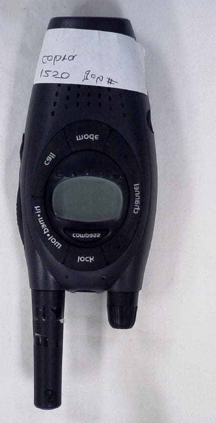
Click to zoom
Application Details
- Equipment Class
- FRF - Part 95 Family Radio Face Held Transmitter
- Date of Grant
- Jan 23, 2003
- Application Purpose
- Original Equipment
- Date of Application
- Jan 23, 2003
- Equipment Note
- 22 CH FRS/ GMRS Transceiver
- Frequency Range
- 462.56250000 - 467.71250000
- Country
- United States
Documents & Files
Document Text
Text extracted from the exhibit documents filed with the FCC. Open a document above to read the original.
Users Manual
Customer Assistance WarrantyIntroduction 25 Nothing comes close to a Cobra ™ Operation General Specifications • Nominal Unit Nominal Unit C. Transmitter 1. Conducted Power GMRS . . . . . . . . . . . . . . . . . . . .W3 FRS Only . . . . . . . . . . . . . . . . .mW500 2. Carrier Frequency Stability . . . ±Hz 500 3. Modulation Limiting . . . . . . . . KHz 2.5 4. Carrier Attack Time . . . . . . . . . mS 80 5. Audio Frequency Response @ 300 HZ . . . . . . . . . . . . . . . . . dB-12 @ 2500 HZ . . . . . . . . . . . . . . . . dB+6 6. Audio Distortion . . . . . . . . . . . . % 3 7. Hum Noise . . . . . . . . . . . . . . . . dB 30 8. Transient Frequency Behavior a) TX On . . . . . . . . . . . . . . . . . mS 30 b) TX Off . . . . . . . . . . . . . . . . . mS 5 A. FRS/GMRS Frequency Allocation and Compatibility Important:Please note that Cobra ® GMRS models with 15 channels may designate different channel numbers for the same frequency. For example, a Cobra ® 15 channel GMRS model would need to be tuned to channel 11 in order to communicate with a 22 channel GMRS tuned to channel 15. Please refer to the chart below for channel/ frequency number compatibility. A = 22 Channel GMRS Channel No. Displayed B = Channel No. For 15 Channel GMRS Models C = Type of Radio Service D = Frequency in MHz E = Power in Watts ERP a = 3.0/2.0/0.5 (selectable) b = 0.5 AB CDE 1 1 FRS/GMRS 462.5625 a 2 2FRS/GMRS462.5875 a 3 3FRS/GMRS 462.6125 a 4 4 FRS/GMRS 462.6375 a 5 5 FRS/GMRS 462.6625 a 6 6 FRS/GMRS 462.6875 a 7 7 FRS/GMRS 462.7125 a 8 FRS 467.5625 b 9 FRS 467.5875b 10 FRS467.6125 b 11 FRS 467.6375b 12 FRS 467.6625 b 13 FRS 467.6875 b 14 FRS 467.7125b 15 11 GMRS 462.5500 a 16 8 GMRS 462.5750 a 17 12 GMRS 462.6000 a 18 9 GMRS 462.6250 a 19 13 GMRS 462.6500 a 20 10 GMRS 462.6750 a 21 14 GMRS 462.7000 a 22 15 GMRS 462.7250 a B. Receiver 1. Sensitivity For 12 DB SINAD . . . . . . . . . . dBm -121 For Call Signal Detection . . . . dBm -121 2. Max. Audio Output @10% THD . . . . . . . . . . . . . . . mW200 3. Max. S/N Ratio @ 1mV RF Input . . . . . . . . . . . dB 50 4. Squelch a) Sensitivity . . . . . . . . . . . . . . dBm-121 b) Attack Time . . . . . . . . . . . . . mS 150 c) Closing Time . . . . . . . . . . . . mS 200 5. Audio Frequency Response @ 300 HZ . . . . . . . . . . . . . . . . . dB -3 @ 2500 HZ . . . . . . . . . . . . . . . . dB -10 6. Signal Displacement BW . . . +/-KHz5 7. Adjacent Channel Rejection . . . dB 60 8. Intermodulation Rejection . . . . dB 65 9. Spurious Response Rejection . dB 55 D.Power Supply 1. Battery Life (5:5:90 RATIO) With Alkaline Batteries . . . . . . . HR 24 2. Battery Operating Range . . . . . . V4.2 - 6.0 Nominal Unit
ID Label/Location Info
BBOPR4000WX Label and Placement BBOPR4000WX PR4000WX
Operational Description
TECHNICAL DESCRIPTION PR4000 WX FCC ID: BBOPR4000WX Page 1 December 6, 2002 A). GENERAL DESCRIPTION The PR4000 WX radio is a self-contained transceiver unit intended for use as a general communication tool. The PR4000 WX model is a combination FRS/GMRS unit and has 22 channels of which channels 1-7 share the FRS channels 1-7. The PR4000 WX has the capability of switching transmit power .5W, 2W and 3W with FRS channels 8-14 limited to .5W only. Other features include a CTCSS system with 38 pre- defined, user selectable sub-audible tones for channel quieting. The useable range, while dependent upon terrain, power setting and other radio propagation principles, is typically seven miles based on the transmit power specified at 3 watts ERP and 2 miles based on the transmit power of 1/2 watt ERP. Product features are as follows: MODEL PR4000WX FEATURES Number of Channels 22 CTCSS SubCodes 38 Range (Low Power) 2 Miles Range (Medium Power) 5 Miles Range (High Power) 7 Miles Alkaline Battery Source 4 AA Weather Channels 10 Transmitter Output Power 0.5/2/3 W Channel Indicator LCD Backlit LCD Yes Detachable Antenna No Call/Ring Alert 10 Tones Auto Squelch Yes Internal VOX Yes Automatic Battery Save Yes Auto Channel/User State Saver Yes Channel Scan Function Yes Channel Monitor Yes Key Lock Yes Supports NiMH Battery Source Yes Low Battery Alert and/or Gauge Both Water Resistant Yes Headset Jack Yes On/Off/Volume Rotary Belt Clip Included Yes Chg Contacts on radio bottom Yes TECHNICAL DESCRIPTION PR4000 WX FCC ID: BBOPR4000WX Page 2 B). FREQUENCY DETERMINING CIRCUITS The fundamental frequency for both the transmitter and the receiver local oscillators are controlled by a phase lock loop (PLL) circuit U300 (Toshiba TB31202). The frequency of operation of the voltage controlled oscillator (VCO), composed of Q50 and Q51 operating in cascode, is phase locked to a voltage controlled crystal reference (VCXO) operating at 10.475 MHz (X300). Compensation for temperature variations on the crystal reference is accomplished using a thermister (TH300) to change the reactance of the reference crystal circuitry. Compensation for voltage variations on the crystal reference is accomplished through a supply voltage regulator The VCO is locked to the fundamental of the transmit signal in the transmit mode and is locked to the receive 1 st LO (Fundamental channel frequency minus 21.4 MHz) in the receive mode. The crystal reference frequency is fed through a doubler circuit to generate the 2 nd LO of 20.950 MHz. C). TRANSMITTER CIRCUITS The transmitter amplifies the 0 dBm signal from the VCO to approximately 34.8dBm that is fed to the antenna. The transmitter is a three stage amplifier composed of Q200, Q201 and Q202. The first stage is operated class A, and the driver and final is operated class AB. The fundamental transmit signal is fed through a low pass filter in order to suppress the harmonics to below –60 dBc. Transmit power level setting is controlled by the micro-controller (U400). When pin 88 of U400 is driven to a logic low level Q200 is biased for 0.5W-conducted and 2W-conducted operation. When pin 88 of U400 is not driven by U400 to a logic level low Q200 is biased for 3W-conducted output mode. When pin 88 of U400 is driven low for 0.5W-conducted or 2W-conducted operation pin 11 of U400 is driven to a logic level high to drive Q203 to turn on D201 to change the matching network load condition to cause the transmitter to output 0.5W- conducted power. The desired frequency modulation of the carrier is accomplished by modulating the current in the VCO directly with the microphone audio signal. The microphone audio is conditioned with a three-pole high pass filter at 300 Hz (U230-C), a hard clipper circuit (U230-B) to limit maximum deviation to +/-2.5 kHz and a three-pole low pass or splatter filter at 2.7 kHz (U230-A). The low pass filter insures that the occupied bandwidth of the FM modulated signal meets FCC requirements under all input conditions. D). RECEIVER CIRCUITS The received signal from the antenna is band limited to 600 Mhz by the transmitter harmonic filter. The desired signal is fed to a low noise amplifier (LNA – Q101) centered from 460 to 470 MHz that provides approximately 15 dB of gain. The output of the LNA is filtered with a SAW filter (SF100) with passband of 460 to 470 MHz and stopband attenuation of 50 dB. The filtered receive signal is one input to the 1 st mixer, the other mixer input (1 st LO) is the output of the VCO at the desired channel frequency minus 21.4 MHz. The output of the mixer is tuned to the 1 st IF of 21.4 MHz. The 1 st IF fed to a crystal filter centered at 21.4 MHz with a bandwidth of 15 kHz. The filtered 1 st IF is then amplified by Q103 and fed to the 2 nd mixer input of the multi-function receiver IC (U130). The 2 nd LO (20.95 MHz) is generated by the 10.475 MHz VCXO that is the reference frequency for the PLL. The 2 nd mixer output of 450 kHz is filtered through a 6 section ceramic filter that in combination with the 21.4 MHz crystal filter provides approximately 55 dB of adjacent channel attenuation. The 450 kHz 2 nd IF is then amplified, limited and fed to a quadrature detector for FM demodulation. The resulting audio output signal is bandpass filtered from 300 to 3 kHz (U150-A, U150-B) and amplified to provide 350 mW of audio power (U160), which differentially drives the 16 ohm speaker. A squelch circuit is provided (U130 pins 10 through 14) to mute TECHNICAL DESCRIPTION PR4000 WX FCC ID: BBOPR4000WX Page 3 the receiver noise under low signal conditions. The squelch circuit amplifies and detects noise in a narrow bandwidth at approximately 7 kHz. When the detected noise exceeds a threshold set to trigger at approximately 12 dB SINAD receive signal strength, the audio output is muted. E). WEATHER RADIO SECTION The weather radio mode is controlled by data sent to U300 from micro-controller (U400). When the weather radio mode is selected the micro-controller (U400) …
Text truncated - open the document above for the full version.
Test Report
APPLICANT: COBRA ELECTRONICS CORPORATION FCC ID: BBOPR4000WX REPORT #: C\COBRA\1250AUT2\1250AUT2TestReport.doc TABLE OF CONTENTS TABLE OF CONTENTS LIST APPLICANT: COBRA ELECTRONICS CORPORATION FCC ID: BBOPR4000WX TEST REPORT: PAGE 1......COVER SHEET - GENERAL INFORMATION & TECHNICAL DESCR. PAGE 2......TECHNICAL DESCRIPTION CONTINUED PAGE 3......RF POWER OUTPUT PAGE 4......MODULATION CHARACTERISTICS PAGE 5......AUDIO FREQUENCY RESPONSE GRAPH PAGE 6......MODULATION LIMITING GRAPH – 300Hz PAGE 7......MODULATION LIMITING GRAPH – 1000Hz PAGE 8......MODULATION LIMITING GRAPH – 2500Hz PAGE 9......AUDIO LOW PASS FILTER GRAPH PAGE 10.....OCCUPIED BANDWIDTH PAGE 11.....OCCUPIED BANDWIDTH PLOT PAGE 12.....OCCUPIED BANDWIDTH PLOT - CW PAGE 13.....SPURIOUS EMISSIONS AT ANTENNA TERMINALS PAGE 14-15..UNWANTED RADIATION PAGE 16.....METHOD OF MEASURING RADIATED SPURIOUS EMISSIONS PAGE 17.....FREQUENCY STABILITY PAGE 18-20..LIST OF TEST EQUIPMENT EXHIBITS CONTAINING: EXHIBIT 1.........FCC ID LABEL SAMPLE & SKETCH OF LOCATION EXHIBIT 2.........EXTERNAL PHOTOGRAPHS EXHIBIT 3.........INTERNAL PHOTOGRAPHS EXHIBIT 4.........BLOCK DIAGRAM EXHIBIT 5.........SCHEMATICS EXHIBIT 6.........USER'S MANUAL EXHIBIT 7.........CIRCUIT DESCRIPTION EXHIBIT 8.........TEST SET UP PHOTO APPLICANT: COBRA ELECTRONICS CORPORATION FCC ID: BBOPR4000WX REPORT #: C\COBRA\1250AUT2\1250AUT2TestReport.doc Page 1 of 20 GENERAL INFORMATION REQUIRED FOR CERTIFICATION 2.1033(c)(1)(2) COBRA ELECTRONICS CORPORATION will manufacture the FCCID: BBOPR4000WX GMRS/FRS COMBINATION TRANSCEIVER in quantity, for use under FCC RULES PART 95. COBRA ELECTRONICS CORPORATION 6500 WEST CORTLAND STREET CHICAGO, IL 60707 2.1033 (c) TECHNICAL DESCRIPTION 2.1033(c)(3) Instruction book. A draft copy of the instruction manual is included as EXHIBIT 6. 2.1033(c) (4) Type of Emission: 10K7F3E 95.631 Bn = 2M + 2DK M = 3000 D = 2350 Bn = 2(3000)+2(2350) = 10.7K GMRS Authorized Bandwidth 20.0 kHz 2.1033(c)(5) GMRS Frequency Range: 1. 462.5500 13. 462.7000 95.621 2. 462.5625 14. 462.7125 3. 462.5750 15. 462.7250 4. 462.5875 16. 467.5500 5. 462.6000 17. 467.5750 6. 462.6125 18. 467.6000 7. 462.6250 19. 467.6250 8. 462.6375 20. 467.6500 9. 462.6500 21. 467.6750 10. 462.6625 22. 467.7000 11. 462.6750 23. 467.7250 12. 462.6875 FRS Authorized Bandwidth 12.5 kHz 2.1033(c)(5) FRS Frequency Range: 1. 462.5625 8. 467.5625 95.627 2. 462.5875 9. 467.5875 3. 462.6125 10. 467.6125 4. 462.6375 11. 467.6375 5. 462.6625 12. 467.6625 6. 462.6875 13. 467.6875 7. 462.7125 14. 467.7125 MHz APPLICANT: COBRA ELECTRONICS CORPORATION FCC ID: BBOPR4000WX REPORT #: C\COBRA\1250AUT2\1250AUT2TestReport.doc Page 2 of 20 2.1033(c)(6)(7)No GMRS shall exceed exceed 50 Watts carrier power. 95.639(a)(1) 95.639(d) No FRS unit, under any condition of modulation, 95.649 shall exceed 0.500W effective radiated power (ERP). There can be no provisions for increasing the power Or varying the power. 2.1033(c)(8) DC Voltages and Current into Final Amplifier: FINAL AMPLIFIER ONLY FOR LOW POWER SETTING INPUT POWER: (6.0V)(.210A) = 1.26 Watts FOR HIGH POWER SETTING INPUT POWER: (6.0V)(.600A) =3.60 Watts 2.1033(c)(9) Tune-up procedure included in users manual. 2.1033(c)(10) Complete Circuit Diagrams: The circuit diagram is included as EXHIBIT 5 of this report. The block diagrams are included as EXHIBIT 4 of this report. 2.1033(c)(11) A photograph or a drawing of the equipment identification label is included as exhibit No. 1. 2.1033(c)(12) Photographs(8"X10") of the equipment of sufficient clarity to reveal equipment construction and layout, including meters, labels for controls, including any view under shields. See exhibits 2-3. 2.1033(c)(13) Digital modulation is not allowed. 2.1033(c)(14) The data required by 2.1046 through 2.1057 is submitted below. APPLICANT: COBRA ELECTRONICS CORPORATION FCC ID: BBOPR4000WX REPORT #: C\COBRA\1250AUT2\1250AUT2TestReport.doc Page 3 of 20 2.1046(a) RF power is measured by the substitution method as outlined in TIA/EIA - 603. With a nominal battery voltage of 6.0 V, and the transmitter properly adjusted the RF output measures: GMRS (HIGH) – 2.1 Watts (MED) – 1.65 Watts (LOW) – 0.438 Watts FRS - 0.438 Watts RF power output. The test procedure used was TIA/EIA-603 S2 APPLICANT: COBRA ELECTRONICS CORPORATION FCC ID: BBOPR4000WX REPORT #: C\COBRA\1250AUT2\1250AUT2TestReport.doc Page 4 of 20 2.1047(a)(b) Modulation characteristics: AUDIO FREQUENCY RESPONSE The audio frequency response was measured in ac- cordance with TIA/EIA Specification 603. The audio frequency response curve is shown on the next page. The audio signal was fed into a dummy microphone circuit and into the microphone connector. The input required to produce 30 percent modulation level was measured. See Page 5 of report. 2.1047(b) Audio input versus modulation The audio input level needed for a particular per- percentage of modulation was measured in accor- dance with TIA/EIA Specification 603. The audio input curves versus modulation are on the following pages. Curves are provided for audio input frequen- cies of 300, 1000, and 3000 Hz. See Pages 6,7 & 8 of report. 95.637 Post Limiter Filter Each GMRS transmitter, except a mobile station transmitter with a power of 2.5Watts or less, must be equipped with an audio low pass filter. At any frequency between 3 & 20 kHz the filter must have an attenuation of 60log (f/3) greater than the attenuation at 1KHz. See Page 9 of report. APPLICANT: COBRA ELECTRONICS CORPORATION FCC ID: BBOPR4000WX REPORT #: C\COBRA\1250AUT2\1250AUT2TestReport.doc Page 5 of 20 AUDIO FREQUENCY RESPONSE PLOT Audio Frequency Response -25 -20 -15 -10 -5 0 5 10 100100010000 Frequency Hz Attenuation dB APPLICANT: COBRA ELECTRONICS CORPORATION FCC ID: BBOPR4000WX REPORT #: C\COBRA\1250AUT2\1250AUT2TestReport.doc Page 6 of 20 MODULATION LIMITING PLOT – 300 Hz 0 0.5 1 1.5 2 2.5 -90-80-70-60-50-40-30-20-10010 dBm Deviation APPLICANT: COBRA ELECTRONICS CORPORATION FCC ID: BBOPR4000WX REPORT #: C\COBRA\1250AUT…
Text truncated - open the document above for the full version.
Test Report
Test Report S/N: 121102-323BBO Test Date(s): December 20, 2002 FCC SAR Evaluation © 2002 Celltech Research Inc.1 of 21 Celltech Research Inc. declares under its sole responsibility that this device was found to be in compliance with the Specific Absorption Rate (SAR) RF exposure requirements specified in FCC 47 CFR §2.1093. The device was tested in accordance with the measurement standards and procedures specified in FCC OET Bulletin 65, Supplement C, Edition 01-01 (General Population / Uncontrolled Exposure). I attest to the accuracy of data. All measurements were performed by me or were made under my supervision and are correct to the best of my knowledge and belief. I assume full responsibility for the completeness of these measurements and vouch for the qualifications of all persons taking them. This test report shall not be reproduced partially, or in full, without the prior written approval of Celltech Research Inc. The results and statements contained in this report pertain only to the device(s) evaluated. Russell W. Pipe Senior Compliance Technologist Celltech Research Inc. DECLARATION OF COMPLIANCE SAR EVALUATION Test Lab CELLTECH RESEARCH INC. Testing and Engineering Lab 1955 Moss Court Kelowna, B.C. Canada V1Y 9L3 Phone: 250-448-7047 Fax: 250-448-7046 e-mail: [email protected] web site: www.celltechlabs.com Applicant Information COBRA ELECTRONICS CORPORATION 6500 West Cortland Street Chicago, IL 60707 Rule Part(s):FCC 47 CFR §2.1093 Test Procedure(s):FCC OET Bulletin 65, Supplement C (01-01) Device Type:Portable UHF GMRS/FRS PTT Radio Transceiver FCC ID:BBOPR4000WX Model(s):PR4000WX Modulation:FM (UHF) Tx Frequency Range(s):462.5500 - 462.7250 MHz (GMRS Channels 15-22) 462.5625 - 462.7125 MHz (FRS/GMRS Channels 1-7) 467.5625 - 467.7125 MHz (FRS Channels 8-14) RF Output Power:2.1 Watts ERP (GMRS) No. of Channels:22 Antenna Type(s):Fixed Battery Type(s):1.5V AA Alkaline (x4) Body-Worn Accessories:Belt-Clip, Lapel Ear-Microphone Max. SAR Measured:0.750 W/kg - Face-held (50% duty cycle) 1.07 W/kg - Body-worn (50% duty cycle) Test Report S/N: 121102-323BBO Test Date(s): December 20, 2002 FCC SAR Evaluation © 2002 Celltech Research Inc.2 of 21 TABLE OF CONTENTS 1.0INTRODUCTION..................................................................... 3 2.0DESCRIPTION OF DUT............................................................ 3 3.0SAR MEASUREMENT SYSTEM ............................................... 4 4.0MEASUREMENT SUMMARY..................................................... 5 5.0DETAILS OF SAR EVALUATION............................................... 6 6.0EVALUATION PROCEDURES................................................... 6-7 7.0SYSTEM PERFORMANCE CHECK............................................ 8 8.0SIMULATED TISSUES............................................................. 9 9.0SAR LIMITS........................................................................... 9 10.0SYSTEM SPECIFICATIONS...................................................... 10 11.0PROBE SPECIFICATION......................................................... 11 12.0SAM PHANTOM...................................................................... 11 13.0LARGE PLANAR PHANTOM..................................................... 11 14.0DEVICE HOLDER.................................................................... 11 15.0TEST EQUIPMENT LIST........................................................... 12 16.0MEASUREMENT UNCERTAINTIES............................................ 13 17.0REFERENCES.......................................................................14 APPENDIX A - SAR MEASUREMENT DATA.............................................15 APPENDIX B - SYSTEM CHECK DATA....................................................16 APPENDIX C - SYSTEM VALIDATION.....................................................17 APPENDIX D - PROBE CALIBRATION....................................................18 APPENDIX E - MEASURED FLUID DIELECTRIC PARAMETERS................19 APPENDIX F - SAM PHANTOM CERTIFICATE OF CONFORMITY..............20 APPENDIX G - SAR TEST SETUP & DUT PHOTOGRAPHS........................21 Test Report S/N: 121102-323BBO Test Date(s): December 20, 2002 FCC SAR Evaluation © 2002 Celltech Research Inc.Cobra Electronics Corporation FCC ID: BBOPR4000WX (Model: PR4000WX)3 of 21 Portable UHF GMRS/FRS PTT Radio Transceiver (462.5500-467.7125MHz) 1.0 INTRODUCTION This measurement report demonstrates compliance of the Cobra Electronics Corporation Model: PR4000WX Portable UHF GMRS/FRS PTT Radio Transceiver FCC ID: BBOPR4000WX with the rules and requirements of FCC 47 CFR §2.1093 (see reference [1]) for the General Population / Uncontrolled Exposure environment. The test procedures described in FCC OET Bulletin 65, Supplement C, Edition 01-01 (see reference [2]) were employed. A description of the product and operating configuration, detailed summary of the test results, methodology and procedures used in the evaluation, equipment used, and the various provisions of the rules are included within this test report. 2.0 DESCRIPTION of Device Under Test (DUT) Rule Part(s)FCC 47 CFR §2.1093 Test ProcedureFCC OET Bulletin 65, Supplement C (01-01) Device TypePortable UHF GMRS/FRS PTT Radio Transceiver FCC IDBBOPR4000WX Model(s)PR4000WX Serial No.Pre-production ModulationFM (UHF) Tx Frequency Range 462.5500 - 462.7250 MHz (GMRS Channels 15-22) 462.5625 - 462.7125 MHz (FRS/GMRS Channels 1-7) 467.5625 - 467.7125 MHz (FRS Channels 8-14) RF Output Power2.1 Watts ERP (GMRS) Battery Type(s)1.5V AA Alkaline (x4) Antenna Type(s)Fixed Body-Worn Accessories Tested Belt-Clip Lapel Ear-Microphone Test Report S/N: 121102-323BBO Test Date(s): December 20, 2002 FCC SAR Evaluation © 2002 Celltech Research Inc.Cobra Electronics Corporation FCC ID: BBOPR4000WX (Model: PR4000WX)4 of 21 Portable UHF GMRS/FRS PTT Radio Transceiver (462.5500-467.7125MHz) 3.0 SAR MEASUREMENT SYSTEM Celltech Research SAR measurement facility utilizes …
Text truncated - open the document above for the full version.
Contact Information
Applicant
Chris de Waal(Senior Project Engineer)
Test Firm
Timco Engineering, Inc.S Sanders
Technical Specifications
| # | Rule Parts | Frequency Range | Power Output | Emission | Tolerance |
|---|---|---|---|---|---|
| 4 | 95B | 462.5625 MHz - 467.7125 MHz | 438.00 mW | 10K7F3E | 2.5 ppm |
Other Applications from Cobra Electronics Corporation
BBOCHEM01
Jul 21, 2026Radar detector
Equipment Class
CRD - Part 15 Radar DetectorBBOPERF600
Jul 13, 2026PERFORMA 600 RADIO DIGITAL BULK, US/COBRA PERFORMA 600 DIGITAL SINGLE PACK, US/COBRA PERFORMA 600 DIGITAL SIX PACK, US/COBRA PERFORMA 600 DIGITAL RADIO, US
Equipment Class
TNF - Licensed Non-Broadcast Transmitter Held to Face
BBOBB650
May 01, 2026VHF Marine Radio Transceiver
Equipment Class
TNF - Licensed Non-Broadcast Transmitter Held to FaceBBOLESS01
Apr 14, 2026Radar detector with Bluetooth
Equipment Class
DTS - Digital Transmission System
BBOCBPT01
Feb 14, 2023Wireless PTT
Equipment Class
DTS - Digital Transmission System