BBOPR4700FRS/GMRS TRANSCEIVER
Cobra Electronics Corporation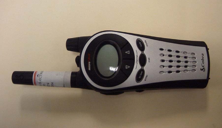
Click to zoom
Application Details
- Equipment Class
- FRF - Part 95 Family Radio Face Held Transmitter
- Date of Grant
- Jan 10, 2005
- Application Purpose
- Original Equipment
- Date of Application
- Jan 10, 2005
- Equipment Note
- FRS/GMRS TRANSCEIVER
- Frequency Range
- 462.56250000 - 467.71250000
- Country
- United States
Documents & Files
Document Text
Text extracted from the exhibit documents filed with the FCC. Open a document above to read the original.
Users Manual
Nothingcomes close to a Cobra ® English The Cobra line of quality products includes: CB Radios • microTALK ® Radios • Radar/Laser Detectors • Safety Alert ® Traffic Warning Systems • Handheld GPS Receivers • Mobile GPS Navigation Systems • HighGear ® Accessories • CobraMarine™ VHF Radios • Power Inverters • Accessories For more information or to order any of our products, please visit our website: www.cobra.com A1 English Making Life Easier and Safer Owner’s Manual Nothingcomes close to a Cobra ® English TWO-WAY RADIO MODEL PR 4700 WX Printed in Philippines Part No. 000-000-P Version A Introduction Staying in touch with your family and friends is convenient and easy when using your microTALK ® radio. Some of the many uses you will discover include: Communicating with others while hiking, biking, and working; keeping track of family and friends at a crowded public event; checking with travel companions in another car; talking with neighbors; arranging meeting spots with others while shopping at the mall. Secure your microTALK ® radio while on the go. Carrying your microTALK ® radio with you is easy when using the belt clip. The belt clip easily attaches to your belt, purse or backpack. Simply squeeze the clip and place it where you prefer. For Assistance in the U.S.A. In this user’s manual, you should find all the information you need to operate your microTALK ® radio. If you require further assistance after reading this manual, Cobra Electronics offers the following customer assistance services: Automated Help Desk English only. 24 hours a day, 7 days a week 773-889-3087 (phone). Customer Assistance Operators English and Spanish. 8:00 a.m. to 6:00 p.m. CT, Monday through Friday (except holidays) 773-889-3087 (phone). Questions English and Spanish. Faxes can be received at 773-622-2269 (fax). Technical Assistance English only. www.cobra.com (on-line: Frequently Asked Questions). English and Spanish. productinfo @cobra.com (e-mail). For Assistance Outside the U.S.A. Contact Your Local Dealer Belt Clip Customer Assistance © 2005 Cobra ® Electronics Corporation 6500 W est Cortland Street Chicago, Illinois 60707 USA www.cobra.com 29 Nothing comes close to a Cobra ® Battery Compartment Battery Door Latch Belt Clip Wrist Strap Connector A3 English Product Features A2 English Product Features Introduction Backlit LCD Display Speaker/ Microphone Hi•Low Power/ Enter Button Call Button On/Off Volume Knob Antenna Lock/Mode Button Channel Up Button Channel Down Button External Speaker/ Microphone/Charge Jack Light/ Max Range Button Talk Button Introduction Backlit LCD Display Important FCC Licensing Information This r adio operates on General Mobile Radio Ser vice (GMRS) frequencies which require a Federal Communications Commission (FCC) license . See page 22 f or licensing and other related information. Maximum range may vary and is based on unobstr ucted line-of-sight comm unication under ideal conditions. Features • Two-Way Radio With up to an 12 miles (19 km) range • 22 Channels Seven shared with FRS/GMRS, seven FRS only, eight GMRS only • 121 Privacy Codes •10 Channel NOAA All Hazards Radio • Hands-Free Operation (VOX) • VibrAlert ® Silent Paging • 10 Channel Memory • Signal Strength Meter • Scan Channel, privacy code, memory • Selectable Hi•Low Power In GMRS • Backlit LCD Display • Button Lock • Call Alert 10 selectable tones • Speaker/ Microphone/ Charge Jack • Roger Beep Selectable on/off • Battery/ Power Saver • Keystroke Tones Selectable on/off • Auto Squelch • Maximum Range Extender •Belt Clip Receive/ Transmit Icon Hi•Low Power Icon Lock Icon Keystroke Tones Icon Call Tones and VibrAlert ® Icon Roger Beep Icon Vox Icon Scan Icon All Hazards Radio Icon Signal Strength Meter Icon Battery Level Indicator Channel Numbers Power Saver Icon CTCSS Privacy Code Numbers Memory Icon Memory Location Number OperationCustomer Assistance Warranty 1 Nothing comes close to a Cobra ® Introduction Caring for Your microTALK ® Radio • Your microTALK ® radio will give you years of trouble-free service if cared for properly. Handle the radio gently. Keep the radio away from dust. Never put the radio in water or in a damp place. Avoid exposure to extreme temperatures. Batteries • To install or replace batteries: 1. Remove belt clip by releasing belt clip latch and sliding clip up. 2.Pull up on the battery door latch to remove the battery compartment cover. 3.Insert four AAA batteries. (Always use high quality alkaline batteries.) Position batteries according to polarity markings. 4.Replace battery compartment cover and belt clip. Contact your local Cobra dealer or Cobra directly for optional battery pack and wall charger accessories. Insert Batteries Pull Up Latch Remove Belt Clip The Basics to Get You Started Your microTALK ® radio is easy to use. To get started, simply: 1.Rotate the On/Off Volumeknob to turn onyour radio. 2.Press the Channel Upor Channel Down button to select a channel. Both radios must be tuned to the same channel/privacy code to communicate. 3.Press and hold the Talkbutton while speaking into the microphone. 4.When finished talking, release the Talk button and listen for a response. Customer Assistance WarrantyIntroduction 3 Nothing comes close to a Cobra ® Operation 2 English Using Your Radio Turning on Your microTALK ® Radio • To turn on your radio: 1. Rotate the On/Off Volumeknob clockwise to turn onyour radio and adjust the volume. A series of tones will indicate the radio is on. Your microTALK ® radio is now in Standby mode, ready to receive transmissions. The radio is always in Standby mode, except when the Talk, Callor Lock/Modebuttons are pressed. Battery Low • Your microTALK ® radio has a battery level meter that shows when battery power is decreasing. The greater the number of bars visible, the stronger the battery level. When the battery level is low, the last bar and “bALo” will flash indicating your batteries should be replaced or, if using rechargeable batteries, recharged. Aut…
Text truncated - open the document above for the full version.
Users Manual
Customer Assistance WarrantyIntroduction 5 Nothing comes close to a Cobra ® Operation 4 English Using Your Radio Volume • To adjust the volume: 1. Rotate the On/Off Volumeknob. Call Button • To alert another person that you are calling: 1. Press and release the Callbutton. The other person will hear a two second call tone. You cannot send or receive transmissions during the two second call tone. See page 22 on how to select from 10 available call tone settings. Selectable High•Low Power Output • When in close proximity to another party or during favorable conditions, you can switch from Highto Low Powerto extend battery life. This feature applies to GMRS Channels 1 through 7 and 15 through 22 only. Channels 8 through 14 operate exclusively on low power. To toggle between high and low power: 1. Press and hold the Hi•Low/Enterbutton for two seconds. When using Channels 1 through 7 and 15 through 22 on high power, the Hiicon will be visible on the display. When using those channels on low power and on Channels 8 through 14, the Lowicon will be visible on the display. Display Illumination • To illuminate your display: 1. Press and release the Light/Max Range button to illuminate the display for 10 seconds. Low Power Icon Hi Power Icon Operation Hi•Low/Enter Button Auto Squelch/Maximum Range • Your microTALK ® radio is equipped with Auto Squelch, which automatically shuts offweak transmissions and unwanted noise due to terrain and conditions. This slightly reduces the Maximum Range at which signals can be heard. You can turn off auto squelch to allow all signals to be received and extend the maximum range of your radio. To briefly turn off auto squelch: 1. Press the Light/Max Rangebutton for less than five seconds. If you hear two beeps, you have turned the maximum range extender on(see below). To turn maximum range extender on: 1. Press and hold the Light/Max Rangebutton for at least five seconds until you hear two beeps which indicates the maximum range extender is on. To turn maximum range extender off: 1. Press and release the Light/Max Range button or change channels. Lock Feature • The Lockfeature locks the Channel, Lock/Modeand Hi•Low Power/Enter buttons to prevent accidental operation. To turn the lock feature on or off: 1. Press and hold the Lock/Modebutton for two seconds. A double beep sound is used to confirm your lock onor offrequest. When in Lock mode, the Lockicon will be displayed. Light/Max Range Light/Max Range Lock/Mode Button Loc k Mode Volume Knob Call Button Customer Assistance WarrantyIntroduction 7 Nothing comes close to a Cobra ® Operation microTALK ® Range • Your microTALK ® radio has a range of up to 12 miles (19 km). Your range will vary depending on terrain and conditions. In flat, open country your radio will operate at maximum range. Buildings and foliage in the path of the signal can reduce the range of the radio. Dense foliage and hilly terrain will further reduce the range of the radio. On FRS channels 8 through 14, your radio automatically switches to low power, which will limit the range the radio can communicate. Remember, you can achieve maximum range by using maximum range extender. See page 5 for details. Scrolling through Mode Functions • By scrolling through the Mode Functions, you will be able to select or turn on/offpreferred features of your microTALK ® radio. When scrolling through the Mode Functions, your radio features will be displayed in the following order: Set CTCSS Privacy Codes Set DCS Privacy Codes Set NOAA All Hazards Radio Channel Set VOX On/Off Set VOX Sensitivity Level Set Memory Locations Set Channel Scan Set Privacy Code Scan Set Memory Location Scan Set VibrAlert ® and/or Call Alert Set Call Tones Set Roger Beep On/Off Set Keystroke Tones On/Off Scroll through the mode functions using the Lock/Modebutton. Each press and release of the Lock/Modebutton will advance to the next mode function. Press the Talkbutton at any point to return the radio to Standbymode. 6 English Using Your Radio Dual Function Buttons Two of the buttons on the microTALK ® radio have Dual Functions; Lock/Mode • Press and release the button to scroll to the next mode function. • Press and hold the button for two seconds or more to turn the lock function onor off Hi•Low Power/Enter • Press and release the button to enter settings. • Press and hold the button for two seconds or more to toggle between high and low power transmission. Speaker/Microphone/Charge Jack • Your microTALK ® radio can be fitted with an external Speaker/Microphone, freeing your hands for other tasks. This same jack also serves as the connecting point for an optional wall charger/adapter. To attach a speaker/microphone: 1. Open the speaker/microphone/charge tab on top of your microTALK ® radio. 2.Insert the plug into the speaker/ microphone/charge jack. To connect a wall charger/adapter: 1. Open the speaker/microphone/charge tab on top of your microTALK ® radio. 2.Insert the wall charger/adapter plug into the speaker/microphone/charge jack. Signal Strength Meter • Your microTALK ® radio has a Signal Strength Meter that shows the strength of your incoming and outgoing transmissions. The ascending bars next to the signal strength indicate the strength of the signal. The greater the number of bars visible, the stronger the signal. The fewer number of bars visible, the weaker the signal. Lock/Mode Button Operation Speaker/Microphone/ Charge Jack Signal Strength Reduced Range Reduced Range Maximum Range Lock/Mode Button Channel Buttons DCS Privacy Code Customer Assistance WarrantyIntroduction 9 Nothing comes close to a Cobra ® Operation 8 English Mode Functions Privacy Codes • Your microTALK ® radio incorporates two advanced coded squelch systems that can help to reduce interference from other users on any given channel. CTCSS (Continuous Tone Coded Squelch System) provides 38 privacy codes and DCS (Digitally Coded Squelch) provides 83 privacy codes. Either system can be used on all channels, but …
Text truncated - open the document above for the full version.
Cover Letter(s)
01 November, 2004 Equipment Authorization Division Office of Engineering and Technology Federal Communications Commission 7435 Oakland Mills Road Columbia, MD 21046 Ref: FCC ID: BBOPR4700 Request for Confidentiality Dear Sirs: With regard to the referenced application, Cobra Electronics Corporation, is requesting confidentiality of certain sections of the accompanying documents. The documents for which Cobra Electronics Corporation is requesting confidentiality are: Schematic Diagram Block Diagram Operational Descriptions This request is made under the provisions of Section 0.457(d) of the Commission’s Rules, and Section 552(b)(4) of the Freedom of Information Act. The material for which confidentiality is requested falls within the scope of Section 552(b)(4) as trade secrets and includes material covered by Section 0.459 of the Commission’s Rules. Sincerely, Robert Mudra Engineering Manager
RF Exposure Info
© 2004 Celltech Labs Inc. 1 of 20 Test Report S/N: 110104BBO-T581-S95U Test Date(s): November 02-03, 2004 Test Type: FCC/IC SAR Evaluation Performed By: Spencer Watson Compliance Technologist Celltech Labs Inc. Reviewed By: Russell W. Pipe Senior Compliance Technologist Celltech Labs Inc. Celltech Labs Inc. declares under its sole responsibility that this wireless portable device has demonstrated compliance with the Specific Absorption Rate (SAR) RF exposure requirements specified in FCC 47 CFR §2.1093 and Health Canada’s Safety Code 6. The device was tested in accordance with the measurement standards and procedures specified in FCC OET Bulletin 65, Supplement C (Edition 01-01) and Industry Canada RSS-102 Issue 1 (Provisional) for the General Population / Uncontrolled Exposure environment. All measurements were performed in accordance with the SAR system manufacturer recommendations. I attest to the accuracy of data. All measurements were performed by me or were made under my supervision and are correct to the best of my knowledge and belief. I assume full responsibility for the completeness of these measurements and vouch for the qualifications of all persons taking them. This test report shall not be reproduced partially, or in full, without the prior written approval of Celltech Labs Inc. The results and statements contained in this report pertain only to the device(s) evaluated. DECLARATION OF COMPLIANCE SAR RF EXPOSURE EVALUATION Test Lab CELLTECH LABS INC. Testing and Engineering Services 1955 Moss Court Kelowna, B.C. Canada V1Y 9L3 Phone: 250-448-7047 Fax: 250-448-7046 e-mail: [email protected] web site: www.celltechlabs.com Applicant Information COBRA ELECTRONICS CORPORATION 6500 West Cortland Street Chicago, IL 60707 United States FCC IDENTIFIER: BBOPR4700 IC IDENTIFER: 906B-PR4700 Model(s): PR4700 / PR4750 Rule Part(s): FCC 47 CFR §2.1093; IC RSS-102 Issue 1 (Provisional) Test Procedure(s): FCC OET Bulletin 65, Supplement C (Edition 01-01) Device Description: Portable UHF FRS/GMRS PTT Radio Transceiver Modulation Type: FM (UHF) Tx Frequency Range(s): 462.5500 - 462.7250 MHz (GMRS Channels 15-22) 462.5625 - 462.7125 MHz (FRS/GMRS Channels 1-7) 467.5625 - 467.7125 MHz (FRS Channels 8-14) Max. RF Output Power Tested: 1.10 Watts ERP (GMRS 462.7125 MHz) Antenna Type(s) Tested: Fixed Helical Battery Type(s) Tested: NiMH x4 (1.2 V AA), NiCd x4 (1.2 V AA), Alkaline x4 (1.5 V AA) Alkaline Type 1: Duracell Procell (2850 mAh) Alkaline Type 2: Energizer E91 (2850 mAh) Body-Worn Accessories Tested: Plastic Belt-Clip Earbud with Lapel-Microphone (P/N: GA-EBM2) Max. SAR Level(s) Evaluated: 0.670 W/kg - Face-held (50% duty cycle) 1.16 W/kg - Body-worn (50% duty cycle) © 2004 Celltech Labs Inc. 2 of 20 Test Report S/N: 110104BBO-T581-S95U Test Date(s): November 02-03, 2004 Test Type: FCC/IC SAR Evaluation TABLE OF CONTENTS 1.0INTRODUCTION......................................................................3 2.0DESCRIPTION OF DUT............................................................. 3 3.0SAR MEASUREMENT SYSTEM................................................. 4 4.0MEASUREMENT SUMMARY...................................................... 5 5.0DETAILS OF SAR EVALUATION................................................ 6 6.0EVALUATION PROCEDURES.................................................... 6 7.0SYSTEM PERFORMANCE CHECK............................................. 7 8.0SIMULATED EQUIVALENT TISSUES.......................................... 8 9.0SAR SAFETY LIMITS............................................................... 8 10.0ROBOT SYSTEM SPECIFICATIONS............................................ 9 11.0PROBE SPECIFICATION.......................................................... 10 12.0PLANAR PHANTOM................................................................. 10 13.0VALIDATION PHANTOM........................................................... 10 14.0DEVICE HOLDER.................................................................... 10 15.0TEST EQUIPMENT LIST........................................................... 11 16.0MEASUREMENT UNCERTAINTIES............................................ 12-13 17.0REFERENCES........................................................................14 APPENDIX A - SAR MEASUREMENT DATA............................................... 15 APPENDIX B - SYSTEM PERFORMANCE CHECK DATA............................ 16 APPENDIX C - SYSTEM VALIDATION PROCEDURES................................. 17 APPENDIX D - PROBE CALIBRATION...................................................... 18 APPENDIX E - MEASURED FLUID DIELECTRIC PARAMETERS................... 19 APPENDIX F - SAR TEST SETUP & DUT PHOTOGRAPHS.......................... 20 Applicant: Cobra Electronics Corporation FCC ID: BBOPR4700IC ID: 906B-PR4700 Model(s):PR4700 / PR4750 Portable UHF FRS/GMRS PTT Radio Transceiver 462.5500 - 467.7125 MHz 2004 Celltech Labs Inc. This document is not to be reproduced in whole or in part without the written permission of Celltech Labs Inc. 3 of 20 Test Report S/N: 110104BBO-T581-S95U Test Date(s): November 02-03, 2004 Test Type: FCC/IC SAR Evaluation This measurement report demonstrates compliance of the Cobra Electronics Corporation Model(s): PR4700 / PR4750 Portable UHF FRS/GMRS PTT Radio Transceiver FCC ID: BBOPR4700 with the SAR (Specific Absorption Rate) RF exposure requirements specified in FCC 47 CFR §2.1093 (see reference [1]), and Health Canada’s Safety Code 6 (see reference [2]) for the General Population / Uncontrolled Exposure environment. The test procedures described in FCC OET Bulletin 65, Supplement C (Edition 01-01) (see reference [3]) and IC RSS-102 Issue 1 (Provisional) (see reference [4]), were employed. A description of the product and operating configuration, detailed summary of the test results, methodology and procedures used in the evaluation, equipment used, and the provisions of the rules are included within this test report. FCC 47 CFR §2.1093…
Text truncated - open the document above for the full version.
Test Report
TIMCO ENGINEERING INC. 849 NW State Road 45 Newberry, Florida 32669 http://www.timcoengr.com 888.472.2424 F 352.472.2030 email: [email protected] APPLICANT: COBRA ELECTRONICS CORPORATION FCC ID: Test Report Product Name: FRS/GMRS TRANSCEIVER FCC ID: BBOPR4700 Applicant: COBRA ELECTRONICS CORPORATION 6500 WEST CORTLAND STREET CHICAGO IL 60707 Date Receipt: DECEMBER 7, 2004 Date Tested: DECEMBER 10, 2004 BBOPR4700 REPORT #: C\COBRA\1857ZUT4\1857ZUT4TestReport.doc COVER SHEET TIMCO ENGINEERING INC. 849 NW State Road 45 Newberry, Florida 32669 http://www.timcoengr.com 888.472.2424 F 352.472.2030 email: [email protected] APPLICANT: COBRA ELECTRONICS CORPORATION FCC ID: TABLE OF CONTENTS LIST TEST REPORT: PAGE 1........GENERAL INFORMATION & TECHNICAL DESCRIPTION PAGE 2........TECHNICAL DESCRIPTION CONTINUED RF POWER OUTPUT PAGE 3........MODULATION CHARACTERISTICS AUDIO FREQUENCY RESPONSE GRAPH PAGE 4........MODULATION LIMITING GRAPH PAGE 5........AUDIO LOW PASS FILTER GRAPH PAGE 6........OCCUPIED BANDWIDTH PAGE 7........OCCUPIED BANDWIDTH PLOT PAGE 8........UNWANTED RADIATION – GMRS PAGE 9........UNWANTED RADIATION - FRS PAGE 10.......METHOD OF MEASURING RADIATED SPURIOUS EMISSIONS PAGE 11.......FREQUENCY STABILITY PAGE 12-17....LIST OF TEST EQUIPMENT EXHIBITS INCLUDED: CONFIDENTIALITY LETTER BLOCK DIAGRAM SCHEMATICS PARTS LIST USERS MANUAL LABEL SAMPLE LABEL LOCATION EXTERNAL PHOTOGRAPHS INTERNAL PHOTOGRAPHS ALIGNMENT PROCEDURE OPERATIONAL DESCRIPTION TEST SET UP PHOTOGRAPHS BBOPR4700 REPORT #: C\COBRA\1857ZUT4\1857ZUT4TestReport.doc TABLE OF CONTENTS TIMCO ENGINEERING INC. 849 NW State Road 45 Newberry, Florida 32669 http://www.timcoengr.com 888.472.2424 F 352.472.2030 email: [email protected] APPLICANT: COBRA ELECTRONICS CORPORATION FCC ID: GENERAL INFORMATION REQUIRED FOR CERTIFICATION 2.1033(c)(1)(2) COBRA ELECTRONICS CORPORATION will manufacture the FCCID: BBOPR4700 GMRS/FRS COMBINATION TRANSCEIVER in quantity, for use under FCC RULES PART 95. COBRA ELECTRONICS CORPORATION 6500 WEST CORTLAND STREET CHICAGO, IL 60707 2.1033 (c) TECHNICAL DESCRIPTION 2.1033(c)(3) Instruction book. A draft copy of the instruction manual is included is included in the exhibits. 2.1033(c) (4) Type of Emission: 10K0F3E 95.631 Bn = 2M + 2DK M = 3000 D = 2K Bn = 2(3000) + 2(2000) = 10K GMRS Authorized Bandwidth 20.0 kHz 2.1033(c)(5) GMRS Frequency Range: 1. 462.5500 13. 462.7000 95.621 2. 462.5625 14. 462.7125 3. 462.5750 15. 462.7250 4. 462.5875 16. 467.5500 5. 462.6000 17. 467.5750 6. 462.6125 18. 467.6000 7. 462.6250 19. 467.6250 8. 462.6375 20. 467.6500 9. 462.6500 21. 467.6750 10. 462.6625 22. 467.7000 11. 462.6750 23. 467.7250 12. 462.6875 FRS Authorized Bandwidth 12.5KHz 2.1033(c)(5) FRS Frequency Range: 1. 462.5625 8. 467.5625 95.627 2. 462.5875 9. 467.5875 3. 462.6125 10. 467.6125 4. 462.6375 11. 467.6375 5. 462.6625 12. 467.6625 6. 462.6875 13. 467.6875 7. 462.7125 14. 467.7125 MHz 2.1033(c)(6)(7) Power Output shall not exceed 0.50 Watts effective 95.639 radiated power. There can be no provisions for 95.649 increasing the power or varying the power. BBOPR4700 REPORT #: C\COBRA\1857ZUT4\1857ZUT4TestReport.doc Page 1 of 17 TIMCO ENGINEERING INC. 849 NW State Road 45 Newberry, Florida 32669 http://www.timcoengr.com 888.472.2424 F 352.472.2030 email: [email protected] APPLICANT: COBRA ELECTRONICS CORPORATION FCC ID: 2.1033(c)(8) DC Voltages and Current into Final Amplifier: FINAL AMPLIFIER ONLY HIGH POWER: (6.0V)(1.20A) = 7.20 Watts LOW POWER: (6.0V)( .60A) = 3.60 Watts 2.1033(c)(9) Tune-up procedure. The tune-up procedure is included in the exhibits. 2.1033(c)(10) Complete Circuit Diagrams: The circuit diagram and block diagram are included in the exhibits. 2.1033(c)(11) A photograph or a drawing of the equipment identification label is included in the exhibits. 2.1033(c)(12) Photographs(8"X10") of the equipment of sufficient clarity to reveal equipment construction and layout, including meters, labels for controls, including any view under shields. 2.1033(c)(13) Digital modulation is not allowed. 2.1033(c)(14) The data required by 2.1046 through 2.1057 is submitted below. 2.10311c)(6)(7) RF power is measured by the substitution method as 2.1046(a) outlined in TIA/EIA - 603. With a nominal battery voltage of 6.0 V, and the transmitter properly adjusted the RF output measures: GMRS - 1.16 Watts ERP – Radiated Substitution FRS - 0.5 Watts – ERP – Radiated Substitution BBOPR4700 REPORT #: C\COBRA\1857ZUT4\1857ZUT4TestReport.doc Page 2 of 17 TIMCO ENGINEERING INC. 849 NW State Road 45 Newberry, Florida 32669 http://www.timcoengr.com 888.472.2424 F 352.472.2030 email: [email protected] APPLICANT: COBRA ELECTRONICS CORPORATION FCC ID: 2.1047(a)(b) Modulation characteristics: AUDIO FREQUENCY RESPONSE The audio frequency response was measured in ac- cordance with TIA/EIA Specification 603. The audio frequency response curve is shown on the next page. The audio signal was fed into a dummy microphone circuit and into the microphone connector. The input required to produce 30 percent modulation level was measured. See plot below. Audio Frequency Response -4 +6 -2 +0 +2 +4 d B 100 10k 200 500 1k 2k 5k Hz BBOPR4700 REPORT #: C\COBRA\1857ZUT4\1857ZUT4TestReport.doc Page 3 of 17 TIMCO ENGINEERING INC. 849 NW State Road 45 Newberry, Florida 32669 http://www.timcoengr.com 888.472.2424 F 352.472.2030 email: [email protected] APPLICANT: COBRA ELECTRONICS CORPORATION FCC ID: 2.1047(b) Audio input versus modulation The audio input level needed for a particular percentage of modulation was measured in accordance with TIA/EIA Specification 603. The audio input curves versus modulation are on the following pages. Curves are provided for audio input frequencies of 300, 1000, and 2500 Hz. See the plot below. Modulation Limiting 2 k H z -20 +20-15 -10 -5+0+5+10+15 dBu BBOPR4700 REPORT #: C\COBRA\1857ZUT4\1857ZUT4TestReport.doc Page 4 of 17 TIMCO ENGINEERING INC. 849 NW State Road 45 Newberry, Florida 32669 http://www.timcoengr.com …
Text truncated - open the document above for the full version.
Test Report
TIMCO ENGINEERING INC. 849 NW State Road 45 Newberry, Florida 32669 http://www.timcoengr.com 888.472.2424 F 352.472.2030 email: [email protected] APPLICANT: COBRA ELECTRONICS CORPORATION FCC ID: Test Report Product Name: FRS/GMRS TRANSCEIVER FCC ID: BBOPR4700 Applicant: COBRA ELECTRONICS CORPORATION 6500 WEST CORTLAND STREET CHICAGO IL 60707 Date Receipt: DECEMBER 7, 2004 Date Tested: DECEMBER 10, 2004 BBOPR4700 REPORT #: C\COBRA\1857ZUT4\1857ZUT4TestReport.doc COVER SHEET TIMCO ENGINEERING INC. 849 NW State Road 45 Newberry, Florida 32669 http://www.timcoengr.com 888.472.2424 F 352.472.2030 email: [email protected] APPLICANT: COBRA ELECTRONICS CORPORATION FCC ID: TABLE OF CONTENTS LIST TEST REPORT: PAGE 1........GENERAL INFORMATION & TECHNICAL DESCRIPTION PAGE 2........TECHNICAL DESCRIPTION CONTINUED RF POWER OUTPUT PAGE 3........MODULATION CHARACTERISTICS AUDIO FREQUENCY RESPONSE GRAPH PAGE 4........MODULATION LIMITING GRAPH PAGE 5........AUDIO LOW PASS FILTER GRAPH PAGE 6........OCCUPIED BANDWIDTH PAGE 7........OCCUPIED BANDWIDTH PLOT PAGE 8........UNWANTED RADIATION – GMRS PAGE 9........UNWANTED RADIATION - FRS PAGE 10.......METHOD OF MEASURING RADIATED SPURIOUS EMISSIONS PAGE 11.......FREQUENCY STABILITY PAGE 12-17....LIST OF TEST EQUIPMENT EXHIBITS INCLUDED: CONFIDENTIALITY LETTER BLOCK DIAGRAM SCHEMATICS PARTS LIST USERS MANUAL LABEL SAMPLE LABEL LOCATION EXTERNAL PHOTOGRAPHS INTERNAL PHOTOGRAPHS ALIGNMENT PROCEDURE OPERATIONAL DESCRIPTION TEST SET UP PHOTOGRAPHS BBOPR4700 REPORT #: C\COBRA\1857ZUT4\1857ZUT4TestReport.doc TABLE OF CONTENTS TIMCO ENGINEERING INC. 849 NW State Road 45 Newberry, Florida 32669 http://www.timcoengr.com 888.472.2424 F 352.472.2030 email: [email protected] APPLICANT: COBRA ELECTRONICS CORPORATION FCC ID: GENERAL INFORMATION REQUIRED FOR CERTIFICATION 2.1033(c)(1)(2) COBRA ELECTRONICS CORPORATION will manufacture the FCCID: BBOPR4700 GMRS/FRS COMBINATION TRANSCEIVER in quantity, for use under FCC RULES PART 95. COBRA ELECTRONICS CORPORATION 6500 WEST CORTLAND STREET CHICAGO, IL 60707 2.1033 (c) TECHNICAL DESCRIPTION 2.1033(c)(3) Instruction book. A draft copy of the instruction manual is included is included in the exhibits. 2.1033(c) (4) Type of Emission: 11K0F3E 95.631 Bn = 2M + 2DK M = 3000 D = 2500 Bn = 2(3000) + 2(2500) = 11K GMRS Authorized Bandwidth 20.0 kHz 2.1033(c)(5) GMRS Frequency Range: 1. 462.5500 13. 462.7000 95.621 2. 462.5625 14. 462.7125 3. 462.5750 15. 462.7250 4. 462.5875 16. 467.5500 5. 462.6000 17. 467.5750 6. 462.6125 18. 467.6000 7. 462.6250 19. 467.6250 8. 462.6375 20. 467.6500 9. 462.6500 21. 467.6750 10. 462.6625 22. 467.7000 11. 462.6750 23. 467.7250 12. 462.6875 FRS Authorized Bandwidth 12.5KHz 2.1033(c)(5) FRS Frequency Range: 1. 462.5625 8. 467.5625 95.627 2. 462.5875 9. 467.5875 3. 462.6125 10. 467.6125 4. 462.6375 11. 467.6375 5. 462.6625 12. 467.6625 6. 462.6875 13. 467.6875 7. 462.7125 14. 467.7125 MHz 2.1033(c)(6)(7) Power Output shall not exceed 0.50 Watts effective 95.639 radiated power. There can be no provisions for 95.649 increasing the power or varying the power. BBOPR4700 REPORT #: C\COBRA\1857ZUT4\1857ZUT4TestReport.doc Page 1 of 17 TIMCO ENGINEERING INC. 849 NW State Road 45 Newberry, Florida 32669 http://www.timcoengr.com 888.472.2424 F 352.472.2030 email: [email protected] APPLICANT: COBRA ELECTRONICS CORPORATION FCC ID: 2.1033(c)(8) DC Voltages and Current into Final Amplifier: FINAL AMPLIFIER ONLY HIGH POWER: (6.0V)(1.20A) = 7.20 Watts LOW POWER: (6.0V)( .60A) = 3.60 Watts 2.1033(c)(9) Tune-up procedure. The tune-up procedure is included in the exhibits. 2.1033(c)(10) Complete Circuit Diagrams: The circuit diagram and block diagram are included in the exhibits. 2.1033(c)(11) A photograph or a drawing of the equipment identification label is included in the exhibits. 2.1033(c)(12) Photographs(8"X10") of the equipment of sufficient clarity to reveal equipment construction and layout, including meters, labels for controls, including any view under shields. 2.1033(c)(13) Digital modulation is not allowed. 2.1033(c)(14) The data required by 2.1046 through 2.1057 is submitted below. 2.10311c)(6)(7) RF power is measured by the substitution method as 2.1046(a) outlined in TIA/EIA - 603. With a nominal battery voltage of 6.0 V, and the transmitter properly adjusted the RF output measures: GMRS - 1.16 Watts ERP – Radiated Substitution FRS - 0.5 Watts – ERP – Radiated Substitution BBOPR4700 REPORT #: C\COBRA\1857ZUT4\1857ZUT4TestReport.doc Page 2 of 17 TIMCO ENGINEERING INC. 849 NW State Road 45 Newberry, Florida 32669 http://www.timcoengr.com 888.472.2424 F 352.472.2030 email: [email protected] APPLICANT: COBRA ELECTRONICS CORPORATION FCC ID: 2.1047(a)(b) Modulation characteristics: AUDIO FREQUENCY RESPONSE The audio frequency response was measured in ac- cordance with TIA/EIA Specification 603. The audio frequency response curve is shown on the next page. The audio signal was fed into a dummy microphone circuit and into the microphone connector. The input required to produce 30 percent modulation level was measured. See plot belo…
Text truncated - open the document above for the full version.
Contact Information
Applicant
Chris de Waal(Senior Project Engineer)
Test Firm
Timco Engineering, Inc.Sid Sanders
Technical Specifications
| # | Rule Parts | Frequency Range | Power Output | Emission | Tolerance |
|---|---|---|---|---|---|
| 2 | 95B | 462.5625 MHz - 467.7125 MHz | 500.00 mW | 11K0F3E | 1.5 ppm |
Other Applications from Cobra Electronics Corporation
BBOCHEM01
Jul 21, 2026Radar detector
Equipment Class
CRD - Part 15 Radar DetectorBBOPERF600
Jul 13, 2026PERFORMA 600 RADIO DIGITAL BULK, US/COBRA PERFORMA 600 DIGITAL SINGLE PACK, US/COBRA PERFORMA 600 DIGITAL SIX PACK, US/COBRA PERFORMA 600 DIGITAL RADIO, US
Equipment Class
TNF - Licensed Non-Broadcast Transmitter Held to Face
BBOBB650
May 01, 2026VHF Marine Radio Transceiver
Equipment Class
TNF - Licensed Non-Broadcast Transmitter Held to FaceBBOLESS01
Apr 14, 2026Radar detector with Bluetooth
Equipment Class
DTS - Digital Transmission System
BBOCBPT01
Feb 14, 2023Wireless PTT
Equipment Class
DTS - Digital Transmission System