BBOPR560FRS/GMRS TRANSCEIVER
Cobra Electronics Corporation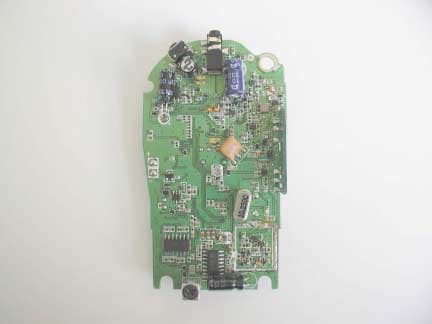
Click to zoom
Application Details
- Equipment Class
- FRF - Part 95 Family Radio Face Held Transmitter
- Date of Grant
- Oct 09, 2003
- Application Purpose
- Original Equipment
- Date of Application
- Oct 09, 2003
- Equipment Note
- FRS/GMRS TRANSCEIVER
- Frequency Range
- 462.56250000 - 467.72000000
- Country
- United States
Documents & Files
Document Text
Text extracted from the exhibit documents filed with the FCC. Open a document above to read the original.
Users Manual
NothingComes Close To A Cobra ® English The Cobra ® line of quality products includes: CB Radios microTALK ® Radios Radar/Laser Detectors Safety Alert ® Traffic Warning Systems Accessories GPS (Global Positioning System) HighGear ® Accessories Power Inverters Marine VHF Radios For more information or to order any of our products, please visit our website: www.cobra.com A1 English Making Life Easier & Safer Introduction Staying in touch with your family and friends is convenient and easy when using your microTALK ® radio. Some of the many uses you will discover include: Communicating with others while hiking, biking, and working; keeping track of family and friends at a crowded public event; checking with travel companions in another car; talking with neighbors; arranging meeting spots with others while shopping at the mall. Secure your microTALK ® radio while on the go. Carrying your microTALK ® radio with you is easy when using the belt clip or wrist strap. The belt clip easily attaches to your belt, purse, or backpack. Simply squeeze the clip and place it where you prefer. For Assistance In the U.S.A. In this user’s manual, you should find all the information you need to operate your microTALK ® radio. If you require further assistance after reading this manual, Cobra ® Electronics offers the following customer assistance services: Automated Help Desk English only. 24 hours a day, 7 days a week 773-889-3087 (phone). Customer Assistance Operators English and Spanish. 8:00 a.m. to 6:00 p.m. CT, Monday through Friday (except holidays) 773-889-3087 (phone). Questions English and Spanish. Faxes can be received at 773-622-2269 (fax). Technical Assistance English only. www.cobra.com (on-line: Frequently Asked Questions). English and Spanish. productinfo @cobra.com (e-mail). For Assistance Outside the U.S.A. Contact Your Local Dealer Belt Clip Wrist Strap Customer Assistance ©2003 Cobra ® Electronics Corporation 6500 West Cortland Street Chicago, Illinois 60707 USA www.cobra.com PR560WX 2-WAY RADIO MODEL NothingComes Close To A Cobra ® English Owner’s Manual Printed in Philippines Part No. 480-112-P OperationWarrantyIntroductionCustomer Assistance Name Address (No P.O. Boxes) CityState/ProvinceZipCountry Telephone Credit Card Number Type: ❒Visa ❒Mastercard ❒DiscoverExp. Date Customer Signature Item #U.S. Cost EachQtyAmount U.S. Subtotal (Tax if Applicable) Shipping/Handling Total Ordering From U.S. Call 773-889-3087 for pricing or visit www.cobra.com. For credit card orders:Complete and return this order form to fax number 773.622.2269 or call 773-889-3087 (Press 1 from the main menu) 8:00 a.m. to 6:00 p.m. CT, Monday through Friday. For Mail or Fax Orders: Complete and return this order form to fax number 773.622.2269 or mail to Cobra ® Electronics, Attn: Accessories Dept., 6500 West Cortland Street, Chicago, IL 60707 USA. Make check or money order payable to: Cobra ® Electronics, To order online:Please visit our website www.cobra.com Amount Shipping/Handling* $10.00 or less . . . . . $3.00 $10.01-$25.00 . . . . . $5.50 $25.01-$50.00 . . . . . $7.50 $50.01-$90.00 . . . . $10.50 $90.01-$130.00 . . . $13.50 $130.01-$200.00 . . $16.50 $200.01 plus . . . . . 10% of purchase Tax Table Wisconsin add 5% Indiana, Michigan, Ohio add 6% California add 7.25% Illinois add 8.75% *For AK, HI and PR add additional $26.95 for FedEx Next Day or $10.95 for FedEx 2nd Day. Excludes weekends and holidays shipments. Please allow 2-3 weeks for delivery in the U.S. Prices subject to change without notice. Optional Accessories • You can find accessories at your local Cobra ® dealer, or in the U.S.A. you can order directly from Cobra. ® A3 English Product Features Introduction Backlit LCD Display Important FCC Licensing Information This radio operates on General Mobile Radio Service (GMRS) frequencies which require a Federal Communications Commission (FCC) license. See page14 for licensing and other related information. Receive/ Transmit Tower Icon Low Power Icon Lock Icon VOX Icon Roger Beep Icon Battery Low Main Channel Numbers Power Saver Icon CTCSS Privacy Code Numbers Scan Icon NOAA All Hazards Radio Icon Features • Two-Way Radio With a range up to five (5) miles (8 km). • 22 Channels Seven shared with FRS/GMRS, seven FRS only eight GMRS only. • 38 Privacy Codes • 10 Channel NOAA All Hazards Radio • Hands-Free Operation (VOX) • Backlit LCD Display • Scan (channel, privacy code) • Water Resistant • Speaker/ Microphone Jack • Call Alert (10 selectable tones) • Lock • Roger Beep (selectable On/Off) • Battery/ Power Saver • Auto Squelch • Maximum Range Extender • Belt Clip • Wrist Strap Battery Compartment Battery Door Latch Belt Clip Wrist Strap Connector A2 English Product Features Introduction Lock Button Backlit LCD Display Channel Up/Down Buttons Speaker/ Microphone Call Button Mode Button Antenna Volume Up/ DownButton(s) External Speaker/ Microphone Jack Light/Max Range Button Talk Button On/Off Power Button OperationCustomer AssistanceWarranty 1 Nothing comes close to a Cobra ® Introduction Caring for Your microTALK ® Radio • Your microTALK ® radio will give you years of trouble-free service if cared for properly. Handle the radio gently. Keep the radio away from dust. Never put the radio in water or in a damp place. Avoid exposure to extreme temperatures. Batteries • To Install or Replace Batteries: 1. Remove belt clip by releasing belt clip latch and sliding clip up. 2. Pull down on the Battery Door Latchto remove the battery compartment cover. 3. Insert four AAA batteries. (Always use high quality alkaline batteries.) Position batteries according to polarity markings. 4. Replace Battery Compartment cover and belt clip. See information on page17 for optional battery pack and desktop charger accessories ordering instructions. Insert Batteries Pull Down Lock Latch Remove Belt Clip The Basics to Get You Started Your microTALK ® radio is easy to use. To get started, simply: 1. Press the Powerbutton to turn On yo…
Text truncated - open the document above for the full version.
Operational Description
7.THEORY OF OPERATION Circuit Compositions and Operation Theory The basic explanation for the circuit composition the two board controlling the analog circuit parts and the digital circuit parts. Receiver Transmission parts are composed in the double conversion system, which has the 1st IF Frequency of 10.7 MHz and 2nd IF Frequency of 450 kHz. With the saw filter, which has an excellent band characteristic and sharp characteristic, the 2 poles CF used in the 1st IF, and the sensitivity repression is reduced for the more stable reception. RF Frontend The signal received by the antenna will be transmitted to the band pass filter through the antenna switching circuit consisted of LT6, LT7, CT24, CT25 and CT23. The front RF amplifier transistor QR1 consists of the saw filter and input/output band pass filter. Saw filter has the bandwidth of approximately 4 MHz, primarily diminishes the other signal rather then the 1st IF image and other signal within the reception band and amplifies only the necessary signal within the RF. 1st Mixer The receiver signal which has been amplified in the RF fronted is provided to the base of the 1st mixer QR2. The 1st L/O signal provide from the VCO is supplied to the emitter of QR2 and converted to the 1st IF 10.7 MHz. 1st IF Filter and 1st IF Amplifier The signal coverted by QR2 to 10.7 MHz, the 1st frequency, change its impedance through CR14, LR5 and then is infused to the fundamental CF which has the center frequency of 10.7 MHz and the width of +/- 30 kHz. Here, the signal reduces the image and other unwanted signal for the 2nd IF. Then the signal is infused to the IC11. The IC11 which functions as the 2nd mixer, the 2nd IF amplifier, and the FM detector,RSSI,PREMIC,compander,PLL circuit. 2nd Mixer, and IF, FM Detector The receiver IF signal of 10.7 MHz, which has been infused to IC11 is mixed with the 2nd L/O signal of 10.250MHz, and converted to 450 kHz, the 2nd IF frequency. The receiver signal converted to the 2nd IF frequency passed through the FC2, the ceramic filter of 450 kHz again. After the limiting inside the IC11 and the FM demodulating by the quadrature detector inside the IC11, the signal offers the output through the 21th pin of IC11. The 2nd L/O signal of 10.250MHz, which infused to the IC11 filters and uses directly the crystal of 10.250 MHz. The squelch circuit is composed to detect the noised from the received signal demodulate in the 31th pin of the IC11. For this purpose, the noise filter is using the OP amplifier inside the IC11. Transmitter The transmission parts of the PR-560 are designed to amplify the RF signal oscillated and modulated by the synthesizer to approximately 1(0.5) W by the power transistor of QT3. TX Power (QT3) The transmitted signal of approximately 1(0.5)W, combined at the driver TR is supplied to the base of the QT3 amplifier. The transmitted signal amplified to 1W here passes the TX LPF of the 2nd characteristic of the LT4 and the LT5, and RX/TX switching takes place by the DT2. After this, the signal is provided to the antenna the TX LPF of the 1st characteristics, consisted of the LT6. Frequency Synthesizer Voltage Control Oscillator (VCO) The VCO of oscillates 462.5625 MHz to 462.7250 MHz under the transmission condition and 451.8625 MHz to 457.0125 MHz under the reception condition. The VCO consists of the clip oscillator of the QV2, and contains the oscillator frequency of approximately 10.7MHz during the transmission/reception conversion. That is since the VCO should oscillate relatively low frequency during reception compared to transmission, the DV2 is directly biased by the QV2. Therefore as a result, the CV6 is added in parallel to the resonance circuit of the VCO to oscillate a low frequency. During transmission, a relatively high frequency should be oscillating compared to reception. Therefore, the DV2 is adversely biased by the QV1, and as a result, the CV6, which is added unparallel to the circuit of the VCO is removed to oscillate the desired transmission frequency. The IC11 PLL IC controls the VCO in order to oscillate the accurate frequency. The output frequency of the VCO is supplied to the 44 th pin of IC11. At the IC11, TCXO(10.250MHz) by the TCXO-1 is compared to the output frequency of the VCO. The VCO is controlled the loop filter consisted of the RR10, RL5,RL6, and the CL5, in order to oscillate the stable frequency wanted for the radio. The VCO controlled voltage which has passed the loop filter is supplies to the DV1 varactor diode, and the VCO an oscillate the PLL programmed frequency by the capacity variation in the DV1. In addition, the LV1 on the VCO circuit function as frequency for the VCO to be properly controlled. RX/TX Buffer (CF5,6) The RF signal oscillate at the VCO is provide to the CF5 RX 1st mixer through the CF5 during the reception, and is provide to the QT2 power driver amplifier through the QT3 during the transmission. PLL Frequency Synthesizer (AN6311FA) The PLL synthesizer of the signal loop PLL circuit with the reference of 6.25 kHz. The IC11 includes all the function such as the reference oscillator, the driver, the phase detector, the lock detector, and the programmable divider. At the reference oscillator, the 10.250 MHz TCXO of the TCXO is connected to the pin 52,53 of the IC11 to oscillate the frequency of 10.250MHz. The TCXO (10.250MHz) is the temperature compensation circuit to maintain the frequency within the allowable error range even under a low temperature of -30 . The phase detector sends out the output power to the loop filter through 44 pin of the IC11. IF the oscillation frequency of the VCO is low compared to the referenced frequency, the phase detector sends out the output power in positive pulse. If the oscillation frequency of the VCO is high, phase detector send out can maintain the frequency set. The programmable divider maintains the desired frequency with control from the CPU. The dividing ratio, "N" to oscillate the desired frequency is as b…
Text truncated - open the document above for the full version.
Parts List/Tune Up Info
8. Alignment instructions WARNING Any repairs or adjustments should be made under the supervision of a qualified radiotelephone technician. TRANSMITTER 1.Power Supply Voltage The Power supply voltage should be set for 6.0VDC measured at the radio during transmit. Periodically check the power supply voltage during the alignment procedure. 2.Frequency Setting A. Connect a frequency counter or Communications Service Monitor to the antenna connector through an RF power attenuator (10 watt minimum rating, 20 dB minimum attenuation). B. Depress the PTT switch. C. Adjust the CTX1 trimmer capacitor such that the output frequency is equal to the channel frequency with a maximum error of +/- 200 Hz. D. Release the PTT switch. 3. Output Power Alignment. A. Set the power supply voltage for 6.0VDC. B. Connect a Communications Service Monitor or a wattmeter and dummy load to the antenna connector. C. Depress the PTT switch. D. To be convinced for 1.0(0.5) Watt output power with a maximum error of +/- 0.5(0.4-0.8) Watt. E. Release the PTT switch. 4. Deviation Adjustment. A. Connect an audio generator to the microphone jack JIG. The audio frequency Should be set at 1 KHz. B. Connect an FM deviation meter or Communications Service Monitor to the antenna connector through an RF power attenuator (10 watt minimum rating, 20 dB minimum attenuation). Set the monitor to read peak deviation. C. Depress the PTT switch. D. Adjust the audio generator level 100 mV rms. E. Adjust SV3 for +/- 2.3 KHz maximum deviation. (With CTCSS tone) F. To be convinced +/- 2.0KHz without CTCSS tone.(1.5KHz dev. 20dB up) g. Release the PTT switch. RECEIVER NOTE: Insure that the proper channel has been selected before preceding with the alignment procedure. 1. Power Supply Voltage The proper voltage for testing is 6.0 VDC. 2. Receiver Alignment A. Connect an RF signal generator or Communications Service Monitor to the antenna connector. B. Connect a SINAD meter and oscilloscope across the speaker terminals. C. Set the output level of the RF signal generator for -47 dBm. The generator should be set for +/- 1.5 KHz deviation of a 1 KHz tone. D. Set the audio output level for 0.6 Vrms. by adjusting volume. E. Reduce the output level of the RF signal generator for produce a 6-12 dB SINAD indication.
Parts List/Tune Up Info
9. SEMICONDUCTORS AND FUNCTIONS ) QV1 KRC404E K.E.C RX/TX VCO SWITCHING QV2 2SC4226-R25 N.E.C OSCILLATOR Q1 2SC4226-R25 N.E.C VCO BUFFER QR1 2SC4226-R25 N.E.C RX 1’st AMP. QR2 2SC4226-R25 N.E.C RX 1’st MIXER QR3 KRC404E K.E.C CTCSS PROCESSING QR4 KRC404E K.E.C AUDIO MUTE CONTROL QS5 KRA304E K.E.C AUDIO MUTE CONTROL QR5 KRC404E K.E.C AUDIO AMP.POWER SWITCHING QR6 KRA226S K.E.C AUDIO AMP.POWER SWITCHING QR10 KRC410E K.E.C AUDIO PATH CONTROL QWS1 KRA305E K.E.C WEATHER B+ CONTROL QW1 2SC4226-R25 N.E.C WEATHER 1’st AMP. QW2 KTC4080E K.E.C WEATHER 1’st MIXER QW3 KTC4080E K.E.C WEATHER VCO BUFFER QW4 2SC4226-R25 N.E.C WEATHER OSCILLATOR QT1 2SC4226-R25 N.E.C TX AMP BUFFER QT2 2SC4226-R25 N.E.C TX AMP DRIVER QT3 DRF1601 A.U.K TX MAIN AMP QS1 KRA305E K.E.C RX B+ SWITCHING QS2 KRA305E K.E.C POWER SAVER CONTROL QS3 KTC410E K.E.C TX HI/LOW POWER CONTROL QS4 KR3105E K.E.C TX B+ SWITCHING QS6 KRA304E K.E.C VDD CONTROL QS7 KRA305E K.E.C EXTERNAL PTT SWITCHING QS8 KRA310E K.E.C BACK LIGHT LED CONTROL QS9 KTC3875 K.E.C ALERT SWITCHING QWS3 KRA305E K.E.C INTERNAL MIC B+ CONTROL QWS2 KRC404E K.E.C VOLUME BALANCE CONTROL QWS4 KRC404E K.E.C CTCSS RX SELECTING QWS5 KRC404E K.E.C CTCSS RX SELECTING ) IC11 AN6311FA MATSUSHITA PLL,MIXER,IF PROSSING IC1 LM324F SGS TOMSON CTCSS TONE DET.(300Hz LPF) IC2 LM324F SGS TOMSON AUDIO 300Hz HPF IC7 IL 386 INTERGRAL AUDIO POWER AMP IC5 TK11140 TOKO REGULATOR IC3 TMP86CH21U/F TOSHIBA CPU
RF Exposure Info
© 2003 Celltech Labs Inc. 1 of 20 Test Report S/N: 091503-420BBO Test Date(s): September 30, 2003 Test Type: FCC SAR Evaluation Celltech Labs Inc. declares under its sole responsibility that this wireless portable device was compliant with the Specific Absorption Rate (SAR) RF exposure requirements specified in FCC 47 CFR §2.1093. The device was tested in accordance with the measurement standards and procedures specified in FCC OET Bulletin 65, Supplement C, Edition 01-01 (General Population / Uncontrolled Exposure). All measurements were performed in accordance with the SAR system manufacturer recommendations. I attest to the accuracy of data. All measurements were performed by me or were made under my supervision and are correct to the best of my knowledge and belief. I assume full responsibility for the completeness of these measurements and vouch for the qualifications of all persons taking them. This test report shall not be reproduced partially, or in full, without the prior written approval of Celltech Labs Inc. The results and statements contained in this report pertain only to the device(s) evaluated. Russell W. Pipe Senior Compliance Technologist Celltech Labs Inc. DECLARATION OF COMPLIANCE SAR RF EXPOSURE EVALUATION Test Lab CELLTECH LABS INC. Testing and Engineering Services 1955 Moss Court Kelowna, B.C. Canada V1Y 9L3 Phone: 250-448-7047 Fax: 250-448-7046 e-mail: [email protected] web site: www.celltechlabs.com Applicant Information COBRA ELECTRONICS CORPORATION 6500 West Cortland Street Chicago, IL 60707 Rule Part(s): FCC 47 CFR §2.1093 Test Procedure(s): FCC OET Bulletin 65, Supplement C (01-01) Device Type: Portable UHF GMRS/FRS PTT Radio Transceiver FCC ID: BBOPR560 Model(s): PR560 Modulation: FM (UHF) Tx Frequency Range(s): 462.5500 - 462.7250 MHz (GMRS Channels 15-22) 462.5625 - 462.7125 MHz (FRS/GMRS Channels 1-7) 467.5625 - 467.7125 MHz (FRS Channels 8-14) RF Output Power Tested: 1 Watt ERP (GMRS) No. of Channels: 22 Antenna Type(s): Fixed Battery Type(s): 1.5 V AAA Alkaline (x4) 1.2 V AAA NiMH (x4) 1.2 V AAA NiCd (x4) Body-Worn Accessories: Belt-Clip, Ear-Microphone Max. SAR Measured: 0.471 W/kg - Face-held (50% duty cycle) 0.570 W/kg - Body-worn (50% duty cycle) © 2003 Celltech Labs Inc. 2 of 20 Test Report S/N: 091503-420BBO Test Date(s): September 30, 2003 Test Type: FCC SAR Evaluation TABLE OF CONTENTS 1.0 INTRODUCTION..................................................................... 3 2.0 DESCRIPTION OF DUT............................................................ 3 3.0 SAR MEASUREMENT SYSTEM ............................................... 4 4.0 MEASUREMENT SUMMARY..................................................... 5 5.0 DETAILS OF SAR EVALUATION............................................... 6 6.0 EVALUATION PROCEDURES................................................... 6 7.0 SYSTEM PERFORMANCE CHECK............................................. 7 8.0 SIMULATED TISSUE MIXTURES............................................... 8 9.0 SAR LIMITS........................................................................... 8 10.0 SYSTEM SPECIFICATIONS...................................................... 9 11.0 PROBE SPECIFICATION......................................................... 10 12.0 PLANAR PHANTOM................................................................ 10 13.0 VALIDATION PHANTOM........................................................... 10 14.0 DEVICE HOLDER.................................................................... 10 15.0 TEST EQUIPMENT LIST........................................................... 11 16.0 MEASUREMENT UNCERTAINTIES............................................ 12-13 17.0 REFERENCES........................................................................ 14 APPENDIX A - SAR MEASUREMENT DATA............................................... 15 APPENDIX B - SYSTEM PERFORMANCE CHECK DATA............................ 16 APPENDIX C - SYSTEM VALIDATION PROCEDURES................................. 17 APPENDIX D - PROBE CALIBRATION...................................................... 18 APPENDIX E - MEASURED FLUID DIELECTRIC PARAMETERS................... 19 APPENDIX F - SAR TEST SETUP & DUT PHOTOGRAPHS.......................... 20 © 2003 Celltech Labs Inc. Cobra Electronics Corporation FCC ID: BBOPR560 (Model: PR560) 3 of 20 Portable UHF GMRS/FRS PTT Radio Transceiver (462.5500-467.7125MHz) Test Report S/N: 091503-420BBO Test Date(s): September 30, 2003 Test Type: FCC SAR Evaluation This measurement report demonstrates compliance of the Cobra Electronics Corporation Model: PR560 Portable UHF GMRS/FRS PTT Radio Transceiver FCC ID: BBOPR560 with the rules and requirements of FCC 47 CFR §2.1093 (see reference [1]) for the General Population / Uncontrolled Exposure environment. The test procedures described in FCC OET Bulletin 65, Supplement C, Edition 01-01 (see reference [2]) were employed. A description of the product and operating configuration, detailed summary of the test results, methodology and procedures used in the evaluation, equipment used, and the various provisions of the rules are included within this test report. Rule Part(s) FCC 47 CFR §2.1093 Test Procedure FCC OET Bulletin 65, Supplement C (01-01) Device Type Portable UHF GMRS/FRS PTT Radio Transceiver FCC ID BBOPR560 Model(s) PR560 Serial No. H309000004 Modulation FM (UHF) Tx Frequency Range 462.5500 - 462.7250 MHz (GMRS Channels 15-22) 462.5625 - 462.7125 MHz (FRS/GMRS Channels 1-7) 467.5625 - 467.7125 MHz (FRS Channels 8-14) RF Output Power Tested 1 Watt ERP (GMRS) Battery Type(s) 1.5 V AAA Alkaline (x4) 1.2 V AAA NiMH (x4) 1.2 V AAA NiCd (x4) Antenna Type(s) Fixed Body-Worn Accessories Tested Belt-Clip, Ear-Microphone 2.0 DESCRIPTION OF DEVICE UNDER TEST (DUT) 1.0 INTRODUCTION © 2003 Celltech Labs Inc. Cobra Electronics Corporation FCC ID: BBOPR560 (Model: PR560) 4 of 20 Portable UHF GMRS/FRS PTT Radio Transceiver (462.5500-467.7125MHz) Test Report S/N: 091503…
Text truncated - open the document above for the full version.
Test Report
APPLICANT: COBRA ELECTRONICS CORPORATION FCC ID: BBOPR560 REPORT #: C\COBRA\1324AUT3\1324AUT3TestReport.doc TABLE OF CONTENTS TABLE OF CONTENTS LIST APPLICANT: COBRA ELECTRONICS CORPORATION FCC ID: BBOPR560 TEST REPORT: PAGE 1......GENERAL INFORMATION & TECHNICAL DESCRIPTION PAGE 2......TECHNICAL DESCRIPTION CONTINUED RF POWER OUTPUT PAGE 3......MODULATION CHARACTERISTICS AUDIO FREQUENCY RESPONSE GRAPH PAGE 4......MODULATION LIMITING GRAPH PAGE 5......AUDIO LOW PASS FILTER GRAPH PAGE 6......OCCUPIED BANDWIDTH PAGE 7......OCCUPIED BANDWIDTH PLOT PAGE 8......SPURIOUS EMISSIONS AT ANTENNA TERMINALS PAGE 9......UNWANTED RADIATION – GMRS PAGE 10.....UNWANTED RADIATION - FRS PAGE 11.....METHOD OF MEASURING RADIATED SPURIOUS EMISSIONS PAGE 12.....FREQUENCY STABILITY PAGE 13-14..LIST OF TEST EQUIPMENT EXHIBITS CONTAINING: EXHIBIT 1.........BLOCK DIAGRAM EXHIBIT 2.........SCHEMATIC EXHIBIT 3.........PARTS LIST EXHIBIT 4.........USERS MANUAL EXHIBIT 5.........LABEL SAMPLE EXHIBIT 6.........LABEL LOCATION EXHIBIT 7.........EXTERNAL PHOTOGRAPHS EXHIBIT 8.........INTERNAL PHOTOGRAPHS EXHIBIT 9.........ALIGNMENT PROCEDURE EXHIBIT 10........OPERATIONAL DESCRIPTION EXHIBIT 11........TEST SET UP PHOTOGRAPH APPLICANT: COBRA ELECTRONICS CORPORATION FCC ID: BBOPR560 REPORT #: C\COBRA\1324AUT3\1324AUT3TestReport.doc Page 1 of 14 GENERAL INFORMATION REQUIRED FOR CERTIFICATION 2.1033(c)(1)(2) COBRA ELECTRONICS CORPORATION will manufacture the FCCID: BBOPR560 GMRS/FRS COMBINATION TRANSCEIVER in quantity, for use under FCC RULES PART 95. COBRA ELECTRONICS CORPORATION 6500 WEST CORTLAND STREET CHICAGO IL 60707 2.1033 (c) TECHNICAL DESCRIPTION 2.1033(c)(3) Instruction book. A draft copy of the instruction manual is included as EXHIBIT 4. 2.1033(c) (4) Type of Emission: 10K5F3E 95.631 Bn = 2M + 2DK M = 3000 D = 2.25K Bn = 2(3000)+2(2250) = 10.5K GMRS Authorized Bandwidth 20.0 kHz 2.1033(c)(5) GMRS Frequency Range: 1. 462.5500 13. 462.7000 95.621 2. 462.5625 14. 462.7125 3. 462.5750 15. 462.7250 4. 462.5875 16. 467.5500 5. 462.6000 17. 467.5750 6. 462.6125 18. 467.6000 7. 462.6250 19. 467.6250 8. 462.6375 20. 467.6500 9. 462.6500 21. 467.6750 10. 462.6625 22. 467.7000 11. 462.6750 23. 467.7250 12. 462.6875 FRS Authorized Bandwidth 12.5KHz 2.1033(c)(5) FRS Frequency Range: 1. 462.5625 8. 467.5625 95.627 2. 462.5875 9. 467.5875 3. 462.6125 10. 467.6125 4. 462.6375 11. 467.6375 5. 462.6625 12. 467.6625 6. 462.6875 13. 467.6875 7. 462.7125 14. 467.7125 MHz 2.10311c)(6)(7) RF power is measured by the substitution method as 2.1046(a) outlined in TIA/EIA - 603. With a nominal battery voltage of 6V, and the transmitter properly adjusted the RF output measures: GMRS - 1.0 Watt ERP, SUBSTITUTION METHOD FRS - 0.5 Watt ERP, SUBSTITUTION METHOD APPLICANT: COBRA ELECTRONICS CORPORATION FCC ID: BBOPR560 REPORT #: C\COBRA\1324AUT3\1324AUT3TestReport.doc Page 2 of 14 2.1033(c)(6)(7) No GMRS shall exceed 50 Watts carrier power 95.639 (a)(1) 95.639 (d) No FRS unit, under any condition of modulation, shall 95.649 exceed 0.500W effective radiated power (ERP). There can be no provisions for increasing the power or varying the power. 2.1033(c)(8) DC Voltages and Current into Final Amplifier: FINAL AMPLIFIER ONLY FOR LOW POWER SETTING INPUT POWER: (6.0V)(.580A) = 3.48 Watts FOR HIGH POWER SETTING INPUT POWER: (6.0V)(.740A) = 4.44 Watts 2.1033(c)(9) Tune-up procedure. The tune-up procedure is included as EXHIBIT # 9. 2.1033(c)(10) Complete Circuit Diagrams: The circuit diagram is included as EXHIBIT 2 of this report. The block diagrams are included as EXHIBIT 1 of this report. 2.1033(c)(11) A photograph or a drawing of the equipment identification label is included as EXHIBIT 4. 2.1033(c)(12) Photographs(8"X10") of the equipment of sufficient clarity to reveal equipment construction and layout, including meters, labels for controls, including any view under shields. See exhibits 7-8. 2.1033(c)(13) Digital modulation is not allowed. 2.1033(c)(14) The data required by 2.1046 through 2.1057 is submitted below. 2.1046(a) RF power output. The test procedure used was TIA/EIA-603 S2 APPLICANT: COBRA ELECTRONICS CORPORATION FCC ID: BBOPR560 REPORT #: C\COBRA\1324AUT3\1324AUT3TestReport.doc Page 3 of 14 APPLICANT: COBRA ELECTRONICS CORPORATION FCC ID: BBOPR560 REPORT #: C\COBRA\1324AUT3\1324AUT3TestReport.doc Page 4 of 14 2.1047(a)(b) Modulation characteristics: AUDIO FREQUENCY RESPONSE The audio frequency response was measured in ac- cordance with TIA/EIA Specification 603. The audio frequency response curve is shown on the next page. The audio signal was fed into a dummy microphone circuit and into the microphone connector. The input required to produce 30 percent modulation level was measured. See plot below. AUDIO FREQUENCY RESPONSE PLOT GOES HERE 09/30/03 09:45:27TIMCO Engineering Inc :17 MAY 90 11:20:29 Ma xFreq .at1 ColorLine StyleThickDataAxis CyanSolid2Anlr.Level A!Norm alizeLeft -10 +10 -7.5 -5 -2.5 +0 +2.5 +5 +7.5 d B 1005k200300400 500 6008001k2k3k4k Hz APPLICANT: COBRA ELECTRONICS CORPORATION FCC ID: BBOPR560 REPORT #: C\COBRA\1324AUT3\1324AUT3TestReport.doc Page 5 of 14 2.1047(b) Audio input versus modulation The audio input level needed for a particular per- percentage of modulation was measured in accor- dance with TIA/EIA Specification 603. The audio input curves versus modulation are on the following pages. Curves are provided for audio input frequen- cies of 300, 1000, and 3000 Hz. See below. MODULATION LIMITING PLOT Modulation Limiting: 2.5KHz, 1.0KHz, 300Hz Cyan Modulation 2.5KHz Green Modulation 1.0KHz Yellow Modulation 300Hz 0 2.4 k H z -40 +5-35 -30 -25-20-15-10-5+0 dBu APPLICANT: COBRA ELECTRONICS CORPORATION FCC ID: BBOPR560 REPORT #: C\COBRA\1324AUT3\1324AUT3TestReport.doc Page 6 of 14 95.637 Post Limiter Filter Each GMRS transmitter, except a mobile station transmitter with a power of 2.5Watts or less, must be equipped with an audio low pass filter. At any frequency between 3 & 20 kHz the filter must have an attenuation o…
Text truncated - open the document above for the full version.
Contact Information
Applicant
Chris de Waal(Senior Project Engineer)
Test Firm
Timco Engineering, Inc.S Sanders
Technical Specifications
| # | Rule Parts | Frequency Range | Power Output | Emission | Tolerance |
|---|---|---|---|---|---|
| 2 | 95A,95B | 462.5625 MHz - 467.72 MHz | 500.00 mW | 10K5F3E | 2.5 ppm |
Other Applications from Cobra Electronics Corporation
BBOCHEM01
Jul 21, 2026Radar detector
Equipment Class
CRD - Part 15 Radar DetectorBBOPERF600
Jul 13, 2026PERFORMA 600 RADIO DIGITAL BULK, US/COBRA PERFORMA 600 DIGITAL SINGLE PACK, US/COBRA PERFORMA 600 DIGITAL SIX PACK, US/COBRA PERFORMA 600 DIGITAL RADIO, US
Equipment Class
TNF - Licensed Non-Broadcast Transmitter Held to Face
BBOBB650
May 01, 2026VHF Marine Radio Transceiver
Equipment Class
TNF - Licensed Non-Broadcast Transmitter Held to FaceBBOLESS01
Apr 14, 2026Radar detector with Bluetooth
Equipment Class
DTS - Digital Transmission System
BBOCBPT01
Feb 14, 2023Wireless PTT
Equipment Class
DTS - Digital Transmission System