BBOS120RRADAR DETECTOR
Cobra Electronics Corporation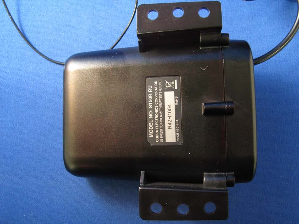
Click to zoom
Application Details
- Equipment Class
- CRD - Part 15 Radar Detector
- Date of Grant
- May 27, 2013
- Application Purpose
- Original Equipment
- Date of Application
- May 27, 2013
- Equipment Note
- RADAR DETECTOR
- Frequency Range
- 33400.00000000 - 36000.00000000
- Country
- United States
Documents & Files
Document Text
Text extracted from the exhibit documents filed with the FCC. Open a document above to read the original.
Users Manual
Typical Fitting 10mm Minimum Typical Fitting Typical Fitting When you have found a suitable location, using the ’L’ shaped mounting bracket as a template, drill between 2 and 4 pilot holes into the selected mounting surface for attaching the bracket using either the self-tapping screws or the nuts and bolts provided. You will need to attach the bracket using at least 2 screws or 2 nuts and bolts to ensure that the bracket is well secured. Remember that there is a lot of vibration within the engine compartment so it is very important that the S120R mounting bracket is secured correctly. User Guide Thank you for purchasing the Cobra iRadar S120R for iPhone, the world’s first connected radar/laser detector. iRadar S120R uses Bluetooth® wireless technology to connect your iPhone®/iPod Touch® to display radar, laser and speed camera alerts. Follow these simple steps to get your iRadar S120R up and running. Cobra iRadar is made for iPod touch (5th Generation) iPod touch (4th Generation) iPhone 5 iPhone 4S iPhone 4 NOTE: Location-based alerts and GPS settings available only with iPhone. Only radar/laser alerts and settings will work with iPod touch. What’s in the box? Cobra iRadar S120R Mounting bracket Screw, nut & bolt pack Cable-tie fasteners Typical Fitting 10mm Minimum Typical Fitting For iPhone S120R Typical Fitting Mounting Notes When mounting and connecting the power cables of the S120R always ensure that you mount the unit and cables away from any moving parts such as air-cooling fans or the fan belt. Always position the unit so that device and power cables do not interfere with any moving parts within the engine compartment or interfer with any part of the vehicle that could endanger you or your passengers. Please check that all surfaces are safe to drill through before beginning any work. Setting Up iRadar S120R The S120R has been designed to be mounted under the hood, behind the vehicle’s grille or within an air intake at the front of the vehicle if appropriate using the ’L’ shaped bracket and screw pack provided. Find a suitable mounting position for the detector, ensuring that the front of the unit has a clear view of the road ahead and is unobstructed by any metallic objects and that there is a sufficient mounting area to attach the ’L’ shaped fixing bracket. The S120R needs to be mounted in as horizontal a position as possible so that it is looking directly down the road ahead. We recommend that you mount the detector either behind the vehicle’s grille (if the openings of the grille are at least 10mm in diameter) or within an air intake at the front of the vehicle. The S120R can be mounted anywhere at the front of the vehicle, but for optimum performance we suggest you mount it as close to the number plate of the vehicle as possible. Connecting the iRadar S120R The S120R is powered by wiring it directly to your vehicles 12v electrical system using the cable supplied Firstly connect the positive side of the cable (Red) to a switched 12v ignition supply. This is a live that is On when the ignition is switched On and Off when the ignition is Off. The negative side of the lead (black) should be connected to a negative ground, so can be attached to any metal portion of the vehicles frame. The LED will blink red if the power connection has been completed successfully. This LED can be located near to the point where the power cable enters the rear of the device. It is not advisable to connect the S120R directly to the vehicle battery as after long periods of vehicle inactivity the vehicle battery may become discharged. Trademark Acknowledgement Cobra ® and the snake design are registered trademarks of Cobra Electronics Corporation, USA. iPhone ® and iPod ® touch are trademarks of Apple, Inc, registered with the U.S. and other countries. The Bluetooth ® word mark is a registered trademark owned by Bluetooth SIG, Inc. and any use of such marks by Cobra Electronics Corporation is under license. Other trademarks and trade names are those of their respective owners. ©2013 Cobra Electronics Corporation Part No. 480-883-P Version A Printed in China NOTE: This device complies with part 15 of FCC rules: Operation is subject to the following two conditions: (1) This device may not cause harmful interference, and (2) This device must accept any interference received including interference that may cause undesired operation. CAUTION: Modifications or parts not approved by Cobra Electronics Corporation may violate FCC Rules and void authority to operate this equipment.
Cover Letter(s)
Equipment Authorization Division Office of Engineering and Technology Federal Communications Commission 7435 Oakland Mills Road Columbia, MD 21046 Ref: FCC ID: BBOS120R Request for Confidentiality Dear Sirs: With regard to the referenced application, Cobra Electronics Corp. is requesting confidentiality of certain sections of the accompanying documents. The documents for which Cobra Electronics Corp. is requesting confidentiality are: S120R Block Diagram S120R (Schematics) S120R Theory of operation This request is made under the provisions of Section 0.457(d) of the Commission’s Rules, and Section 552(b)(4) of the Freedom of Information Act. The material for which confidentiality is requested falls within the scope of Section 552(b)(4) as trade secrets and includes material covered by Section 0.459 of the Commission’s Rules. Pursuant to DA 04-1705 June 15, 2004 of the Commission’s public notice, we also request temporary confidential treatment of information accompanying this application as outlined below until the end of June, 2013 (expected ship date): S120R External Photos S120R Test Setup Photos S120R Quick start Guide S120R Internal Photos Sincerely, Jeff Sterling Director, Microwave Engineering
Test Report
FCC PART 15 RADAR DETECTOR REPORT Applicant COBRA ELECTRONICS CORPORATION Address 6500 WEST CORTLAND STREET CHICAGO IL 60707 USA FCC ID: BBOS120R Product Description RADAR DETECTOR Date Sample Received 5/7/2013 Date Tested 5/8/2013 Tested By JOE SCOGLIO Approved By JOE SCOGLIO Report Number 795AUT13TestReport.doc Test Results PASS FAIL THE ATTACHED REPORT SHALL NOT BE REPRODUCED EXCEPT IN FULL WITHOUT THE WRITTEN APPROVAL OF TIMCO ENGINEERING, INC. 849 NW State Road 45 Newberry, Fl 32669 USA Phone: 888.472.2424 or 352.472.5500 Fax: 352.472.2030 Email: [email protected] Website: www.timcoengr.com Certificate # 0955-01 APPLICANT: COBRA ELECTRONICS CORPORATION FCC ID:: BBOS120R REPORT: C\COBRA\795AUT13\795AUT13TestReport.doc Page 2 of 11 TABLE OF CONTENTS GENERAL REMARKS ............................................................................................................. 3 GENERAL INFORMATION ...................................................................................................... 4 TEST EQUIPMENT LIST ......................................................................................................... 5 TEST PROCEDURES .............................................................................................................. 6 RADIATED SPURIOUS EMISSIONS ........................................................................................ 8 VERTICAL PLOT .................................................................................................................... 9 HORIZONTAL PLOT ............................................................................................................. 10 RADIATED EMISSIONS TEST SETUP PHOTO ....................................................................... 11 APPLICANT: COBRA ELECTRONICS CORPORATION FCC ID:: BBOS120R REPORT: C\COBRA\795AUT13\795AUT13TestReport.doc Page 3 of 11 GENERAL REMARKS The attached report shall not be reproduced except in full without the written permission of Timco Engineering Inc. The test results relate only to the items tested. Summary The device under test does: fulfill the general approval requirements as identified in this test report not fulfill the general approval requirements as identified in this test report Attestations This equipment has been tested in accordance with the standards identified in this test report. To the best of my knowledge and belief, these tests were performed using the measurement procedures described in this report. All instrumentation and accessories used to test products for compliance to the indicated standards are calibrated regularly in accordance with ISO 17025 requirements. Certificate # 0955-01 I attest that the necessary measurements were made, under my supervision, at: Timco Engineering Inc. 849 NW State Road 45 Newberry, Fl 32669 Authorized Signatory Name: Joe Scoglio Engineering Project Manager Date: May 8, 2013 APPLICANT: COBRA ELECTRONICS CORPORATION FCC ID:: BBOS120R REPORT: C\COBRA\795AUT13\795AUT13TestReport.doc Page 4 of 11 GENERAL INFORMATION The test results relate only to the items tested. DUT Description RADAR DETECTOR FCC ID BBOS120R DUT Power Source 110–120Vac/50– 60Hz DC Power Automotive Battery Operated Exclusively Test Item Prototype Pre-Production Production Modifications to DUT None Test Standards FCC Part 15, Subpart B, ANSI C63.4-2003 APPLICANT: COBRA ELECTRONICS CORPORATION FCC ID:: BBOS120R REPORT: C\COBRA\795AUT13\795AUT13TestReport.doc Page 5 of 11 TEST EQUIPMENT LIST Device Manufacturer Model Serial Number Cal/Char Date Due Date 3/10-Meter OATS TEI N/A N/A 12/31/11 12/31/13 3-Meter OATS TEI N/A N/A 12/31/11 12/31/13 3-Meter Semi- Anechoic Chamber Panashield N/A N/A 12/31/11 12/31/13 Analyzer Tan Tower Preamplifier HP 8449B-H02 3008A00372 10/28/11 10/28/13 Analyzer Tan Tower Quasi-Peak Adapter HP 85650A 3303A01690 10/28/11 10/28/13 Analyzer Tan Tower RF Preselector HP 85685A 3221A01400 10/28/11 10/28/13 Analyzer Tan Tower Spectrum Analyzer HP 8566B Opt 462 3138A07786 3144A20661 10/28/11 10/28/13 Antenna: Biconnical Eaton 94455-1 1057 05/31/11 05/31/13 Antenna: Biconnical Electro- Metrics BIA-25 1171 06/13/12 06/13/14 Antenna: Log-Periodic Eaton 96005 1243 05/31/11 05/31/13 LISN Electro- Metrics ANS-25/2 2604 10/28/11 10/28/13 LISN Electro- Metrics EM-7820 2682 02/26/13 02/26/15 Signal Generator HP 8640B 2308A21464 02/23/12 02/23/14 Antenna: Double- Ridged Horn/ETS Horn 1 ETS-Lindgren 3117 00035923 12/07/11 12/07/13 APPLICANT: COBRA ELECTRONICS CORPORATION FCC ID:: BBOS120R REPORT: C\COBRA\795AUT13\795AUT13TestReport.doc Page 6 of 11 TEST PROCEDURES General: This report shall NOT be reproduced except in full without the written approval of TIMCO ENGINEERING, INC. RADIATION INTERFERENCE: Testing was done in accordance with ANSI C63.4-2003. Section 15.35(b) specifies the use of an average detector in this band. In addition, the peak level of an emission shall not exceed the average limit by more than 20 dB using a minimum Resolution Bandwidth (RBW) of 1 MHz and minimum Video Bandwidth (VBW) OF 1 MHz. The following procedure is designed to determine if there are any spurious emissions from the local oscillator within the band of interest along with any additional spurious emissions caused by other circuitry within the device. 1) Determine the frequency of the peak emission: Start Frequency 11.7 GHz Stop Frequency 12.2 GHz RBW equal to or greater than 1 MHz VBW equal to or greater than 1 MHz Detector Function Peak Maximize the emissions with regards to device orientation, antenna polarization, and antenna height. Sweep the band using Max Hold for a minimum of 2 minutes. Record this frequency for measuring the peak emission. In addition record the frequency of other spurious emissions noted. 2) Determine the peak level of the emission: Center Frequency Set to the frequency determined in Step 1 RBW Equal to or greater than 1 MHz VBW Equal to or greater than 1 MHz Detector Function Peak Measure the value of the peak emission u…
Text truncated - open the document above for the full version.
Contact Information
Applicant
Chris de Waal(Senior Project Engineer)
Test Firm
Timco Engineering, Inc.Bruno Clavier
Technical Specifications
| # | Rule Parts | Frequency Range | Power Output |
|---|---|---|---|
| 3 | 15B | 33.40 GHz - 36.00 GHz | - |
Other Applications from Cobra Electronics Corporation
BBOCHEM01
Jul 21, 2026Radar detector
Equipment Class
CRD - Part 15 Radar DetectorBBOPERF600
Jul 13, 2026PERFORMA 600 RADIO DIGITAL BULK, US/COBRA PERFORMA 600 DIGITAL SINGLE PACK, US/COBRA PERFORMA 600 DIGITAL SIX PACK, US/COBRA PERFORMA 600 DIGITAL RADIO, US
Equipment Class
TNF - Licensed Non-Broadcast Transmitter Held to Face
BBOBB650
May 01, 2026VHF Marine Radio Transceiver
Equipment Class
TNF - Licensed Non-Broadcast Transmitter Held to FaceBBOLESS01
Apr 14, 2026Radar detector with Bluetooth
Equipment Class
DTS - Digital Transmission System
BBOCBPT01
Feb 14, 2023Wireless PTT
Equipment Class
DTS - Digital Transmission System