BBOSPX7800RADAR DETECTOR WITH BLUETOOTH MODULE
Cobra Electronics Corporation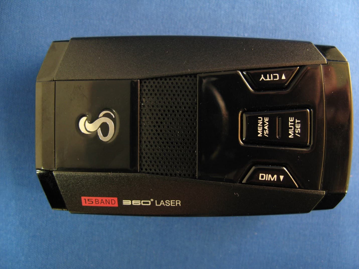
Click to zoom
Application Details
- Equipment Class
- CRD - Part 15 Radar Detector
- Date of Grant
- Aug 06, 2013
- Application Purpose
- Original Equipment
- Date of Application
- Aug 06, 2013
- Equipment Note
- RADAR DETECTOR WITH BLUETOOTH MODULE
- Frequency Range
- 33400.00000000 - 36000.00000000
- Country
- United States
Documents & Files
Document Text
Text extracted from the exhibit documents filed with the FCC. Open a document above to read the original.
Users Manual
Maximum Performance Radar/Laser/Camera Detector SPX 7800BT Operating Instructions Printed in China Part No. 480-890-P Version C Thank you for purchasing Cobra’s maximum performance radar/laser/camera detector. Windshield Bracket Mounting Slot Power/Volume Control 12V Power Jack Menu/Save Button • Press once to enter Menu Mode. • Press again to save settings. Mute/Set Button • Press once to manually mute audio alerts. • In Menu mode, press to save selected settings. City/ Button • Switches between Highway and City filtering modes. • In Menu mode, steps forward through settings selection. Dim/ Button • Adjusts the display brightness. • In Menu mode, steps backward through available settings selection. Mounting Your detector should be mounted on the windshield or dashboard of your vehicle. Two mounting options are included: Suction Cup Mount – This is the best option for portability and mov- ing the detector from car to car. Make sure to thoroughly clean the suction cups and wind- shield mounting area to insure a tight seal. Hook and Loop Fastener– Included for dashboard mounting. Suction Cup Mount Hook & Loop Fastener Your detector should be mounted so that it is oriented parallel to the road. The suction cup mount comes standard bent at a 45° angle. The metal is designed to bend without breaking. Adjust the angle so when mounted the detector is level with the road. Avoid blocking the detector’s view by windshield wiper blades or dark tinting at the top of the windshield. Note: Do not attempt to bend the mount while the detector is attached. Windshield Incorrect Positions Correct Position Powering Plug in your detector using the included cigarette lighter adapter. Note: the adapter includes a USB port that can be used to charge your smartphone or tablet using the manufacturer’s charging cable. Turn your detector on/off by pressing the Power/Volume switch on the side of the unit. The unit will light up. 12V Cigarette Lighter Adapter 12V Power Jack USB Port Power/Volume Control Types of Screens 1. Menu/Settings Screen User and Alert Settings are available for customizing your detector. When Menu is pressed, you will see the screen shown below (Active mode icon will be enlarged/highlighted). 2. Standby Screens Compass Heading: Automatically displays GPS-based heading when connected to a smartphone*. If a GPS signal cannot be received through your smartphone, will be displayed. Vehicle Speed: Automatically displays your current vehicle speed using your smartphone GPS. If a GPS signal cannot be received through your smartphone, will be displayed. City/Highway Indicator: Shows curent filtering mode. Vehicle Battery Voltage: Displays your car battery voltage and automatically warns you if this drops below 11.9V. IntelliMute Indicator: Indicates status of IntelliMute. See IntelliMute section for details. *Works with iPhone and Android smartphones. Internet connection and data plan usage required. • Press to turn power On and Off. • Push forward or pull back to adjust volume . No connection to phone. Connected to phone. Note: Pressing Mute button while connected to an iPhone ® / Android ™ smartphone will toggle between these two screens. 3. Alert Screens Radar bands consist of X-band, K-band, Ka-band, and Ku-band. With Radar signals, the signal strength meter shows signal strength of the radar gun as well as relative proximity to the source. With Ka-band, you will also be notified of the actual Ka-band radar gun frequency being used. With Laser signals, you will always receive full alert and pulse rate (PPS) of the corresponding laser gun being used. Ka Band Alert Signal Strength Frequency Laser Pulse Rate • Level 1= Weakest Signal • Level 5= Strongest Signal Settings Quad-level IntelliSheild ™ False Signal Rejection: Highway Mode provides full immediate response to all signals detected. Use this mode when you are driving on interstate highways. Automatic door openers operate in X and K-band frequencies. To minimize unwanted false alerts in an urban environment where these sources exist, use one of the City Filtering Modes below: • City X: automatically mutes X-band audible alert until signal strength reaches level 3 or above. • City X+K: combined with City X, automatically mutes K-band audible alert until signal strength reaches level 2 or above. • City Plus X+K+Ka: combined with City X+K, adds filtering to Ka-band. • City MAX: Maximum filtering against urban false signal sources. The City modes can also be adjusted by pressing the City button for 2 seconds. IntelliMute ® : IntelliMute allows you to avoid audible alerts you don’t need to hear because you are stopped or moving slowly. By sensing the RPMs of your engine, IntelliMute knows when you are at low speed and automatically mutes alerts. You can set your pre- ferred engine RPM activation point and/or turn on/off IntelliMute by following simple steps that appear on your unit screen, under User Settings and then IntelliMute. IntelliMute ® continued • IntelliMute Engine RPM Activation Point Not Set. • IntelliMute On/Above Set Engine RPM Activation Point. • IntelliMute On/Below Set Engine RPM Activation Point. Note: IntelliMute may not work with some vehicles, especially hybrids or EVs because the detector cannot sense the engine RPMs. In such case, Quad-level IntelliShield City Filter- ing or Auto Mute can help reduce unwanted audible alerts. IntelliMute ® Pro: IntelliMute Pro prevents detection by radar detector detectors (RDDs) such as VG-2, Spectre I and Spectre IV when traveling at slower speeds. It is intended for use by experienced users only. When IntelliMute Pro is turned On and engine RPMs are below the IntelliMute Pro Activation Point, your detector’s radar detec- tion circuits are turned Off to prevent detection by RDDs. IntelliMute Pro cannot be turned on until IntelliMute is turned on and set. The IntelliMute Pro icon will appear in the display when IntelliMute Pro is On and the Activation Point has been set. Whenever engine RPMs a…
Text truncated - open the document above for the full version.
Cover Letter(s)
Equipment Authorization Division Office of Engineering and Technology Federal Communications Commission 7435 Oakland Mills Road Columbia, MD 21046 Ref: FCC ID: BBOSPX7800 Request for Confidentiality Dear Sirs: With regard to the referenced application, Cobra Electronics Corp. is requesting confidentiality of certain sections of the accompanying documents. The documents for which Cobra Electronics Corp. is requesting confidentiality are: SPX 7800 Block Diagram SPX 7800 Circuits (Schematics) SPX 7800 Theory of operation This request is made under the provisions of Section 0.457(d) of the Commission’s Rules, and Section 552(b)(4) of the Freedom of Information Act. The material for which confidentiality is requested falls within the scope of Section 552(b)(4) as trade secrets and includes material covered by Section 0.459 of the Commission’s Rules. Pursuant to DA 04-1705 June 15, 2004 of the Commission’s public notice, we also request temporary confidential treatment of information accompanying this application as outlined below until the end of March, 2013 (expected ship date): SPX 7800 External Photos SPX 7800 Test Setup Photos SPX 7800 Manual SPX 7800 Internal Photos Sincerely, Jeff Sterling Director, Microwave Engineering
External Photos
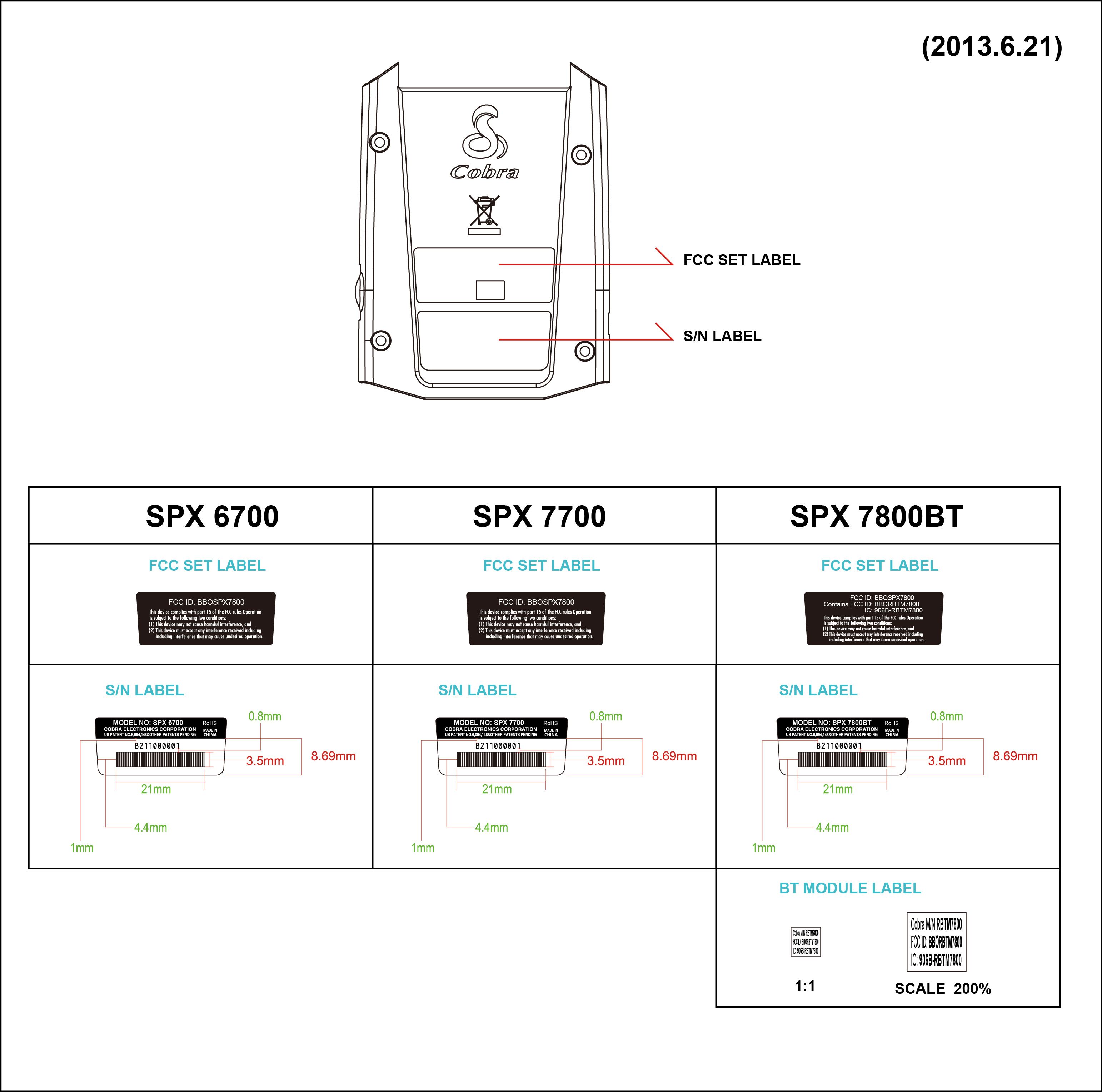
APPLICANT: COBRA ELECTRONICS CORPORATION FCC ID: BBOSPX7800 EXTERNAL PHOTOS
Internal Photos
APPLICANT: COBRA ELECTRONICS CORPORATION FCC ID: BBOSPX7800 INTERNAL PHOTOS
Test Report
FCC PART 15 RADAR DETECTOR REPORT Applicant COBRA ELECTRONICS CORPORATION Address 6500 WEST CORTLAND STREET CHICAGO IL 60707 USA FCC ID: BBOSPX7800 Product Description RADAR DETECTOR WITH BLUETOOTH MODULE Date Sample Received 7/17/2013 Date Tested 7/17/2013 Tested By Joe Scoglio Approved By Joe Scoglio Report Number 1231AUT13TestReport.docx Test Results PASS FAIL THE ATTACHED REPORT SHALL NOT BE REPRODUCED EXCEPT IN FULL WITHOUT THE WRITTEN APPROVAL OF TIMCO ENGINEERING, INC. 849 NW State Road 45 Newberry, Fl 32669 USA Phone: 888.472.2424 or 352.472.5500 Fax: 352.472.2030 Email: [email protected] Website: www.timcoengr.com Certificate # 0955-01 APPLICANT: COBRA ELECTRONICS CORPORATION FCC ID:: BBOSPX7800 REPORT: C\COBRA\1231AUT13\1231AUT13TestReport.docx Page 2 of 12 TABLE OF CONTENTS GENERAL REMARKS ............................................................................................................. 3 GENERAL INFORMATION ...................................................................................................... 4 TEST EQUIPMENT LIST ......................................................................................................... 5 TEST PROCEDURES .............................................................................................................. 6 RADIATED SPURIOUS EMISSIONS ........................................................................................ 8 VERTICAL PLOT .................................................................................................................. 10 HORIZONTAL PLOT ............................................................................................................. 11 RADIATED EMISSIONS TEST SETUP PHOTO ....................................................................... 12 APPLICANT: COBRA ELECTRONICS CORPORATION FCC ID:: BBOSPX7800 REPORT: C\COBRA\1231AUT13\1231AUT13TestReport.docx Page 3 of 12 GENERAL REMARKS The attached report shall not be reproduced except in full without the written permission of Timco Engineering Inc. The test results relate only to the items tested. Summary The device under test does: fulfill the general approval requirements as identified in this test report not fulfill the general approval requirements as identified in this test report Attestations This equipment has been tested in accordance with the standards identified in this test report. To the best of my knowledge and belief, these tests were performed using the measurement procedures described in this report. All instrumentation and accessories used to test products for compliance to the indicated standards are calibrated regularly in accordance with ISO 17025 requirements. Certificate # 0955-01 I attest that the necessary measurements were made, under my supervision, at: Timco Engineering Inc. 849 NW State Road 45 Newberry, Fl 32669 Authorized Signatory Name: Joe Scoglio Engineering Project Manager Date: 7/17/2013 APPLICANT: COBRA ELECTRONICS CORPORATION FCC ID:: BBOSPX7800 REPORT: C\COBRA\1231AUT13\1231AUT13TestReport.docx Page 4 of 12 GENERAL INFORMATION The test results relate only to the items tested. DUT Description RADAR DETECTOR WITH BLUETOOTH MODULE FCC ID BBOSPX7800 DUT Power Source 110–120Vac/50– 60Hz DC Power Battery Operated Exclusively Test Item Prototype Pre-Production Production Modifications to DUT None Test Standards FCC Part 15, Subpart B, ANSI C63.4-2003 APPLICANT: COBRA ELECTRONICS CORPORATION FCC ID:: BBOSPX7800 REPORT: C\COBRA\1231AUT13\1231AUT13TestReport.docx Page 5 of 12 TEST EQUIPMENT LIST Device Manufacture r Model Serial Number Cal/Char Date Due Date 3/10-Meter OATS TEI N/A N/A 12/31/11 12/31/13 3-Meter OATS TEI N/A N/A 12/31/11 12/31/13 3-Meter Semi- Anechoic Chamber Panashield N/A N/A 12/31/11 12/31/13 Analyzer Tan Tower Preamplifier HP 8449B- H02 3008A00372 10/28/11 10/28/13 Analyzer Tan Tower Quasi-Peak Adapter HP 85650A 3303A01690 10/28/11 10/28/13 Analyzer Tan Tower RF Preselector HP 85685A 3221A01400 10/28/11 10/28/13 Analyzer Tan Tower Spectrum Analyzer HP 8566B Opt 462 3138A07786 3144A20661 10/28/11 10/28/13 Antenna: Biconnical Eaton 94455-1 1057 06/14/13 06/14/15 Antenna: Biconnical Eaton 94455-1 1096 05/10/13 05/10/15 Antenna: Biconnical Electro- Metrics BIA-25 1171 06/13/12 06/13/14 Antenna: Log-Periodic Eaton 96005 1243 05/31/13 05/31/15 Antenna: Log-Periodic Electro- Metrics LPA-25 1122 05/09/13 05/09/15 LISN Electro- Metrics ANS-25/2 2604 10/28/11 10/28/13 LISN Electro- Metrics EM-7820 2682 02/26/13 02/26/15 Signal Generator HP 8640B 2308A21464 02/23/12 02/23/14 Antenna: Double- Ridged Horn ETS- Lindgren 3117 00041534 10/05/12 10/05/14 Antenna: Standard gain Horn Systron Donner DBD-520- 20 Not Serialized NO CAL REQUIRED NO CAL REQUIRED APPLICANT: COBRA ELECTRONICS CORPORATION FCC ID:: BBOSPX7800 REPORT: C\COBRA\1231AUT13\1231AUT13TestReport.docx Page 6 of 12 TEST PROCEDURES General: This report shall NOT be reproduced except in full without the written approval of TIMCO ENGINEERING, INC. RADIATION INTERFERENCE: Testing was done in accordance with ANSI C63.4-2003. Section 15.35(b) specifies the use of an average detector in this band. In addition, the peak level of an emission shall not exceed the average limit by more than 20 dB using a minimum Resolution Bandwidth (RBW) of 1 MHz and minimum Video Bandwidth (VBW) OF 1 MHz. The following procedure is designed to determine if there are any spurious emissions from the local oscillator within the band of interest along with any additional spurious emissions caused by other circuitry within the device. 1) Determine the frequency of the peak emission: Start Frequency 11.7 GHz Stop Frequency 12.2 GHz RBW equal to or greater than 1 MHz VBW equal to or greater than 1 MHz Detector Function Peak Maximize the emissions with regards to device orientation, antenna polarization, and antenna height. Sweep the band using Max Hold for a minimum of 2 minutes. Record this frequency for measuring the peak emission. In addition record the…
Text truncated - open the document above for the full version.
Contact Information
Applicant
Chris de Waal(Senior Project Engineer)
Test Firm
Timco Engineering, Inc.Bruno Clavier
Technical Specifications
| # | Rule Parts | Frequency Range | Power Output |
|---|---|---|---|
| 3 | 15B | 33.40 GHz - 36.00 GHz | - |
Other Applications from Cobra Electronics Corporation
BBOCHEM01
Jul 21, 2026Radar detector
Equipment Class
CRD - Part 15 Radar DetectorBBOPERF600
Jul 13, 2026PERFORMA 600 RADIO DIGITAL BULK, US/COBRA PERFORMA 600 DIGITAL SINGLE PACK, US/COBRA PERFORMA 600 DIGITAL SIX PACK, US/COBRA PERFORMA 600 DIGITAL RADIO, US
Equipment Class
TNF - Licensed Non-Broadcast Transmitter Held to Face
BBOBB650
May 01, 2026VHF Marine Radio Transceiver
Equipment Class
TNF - Licensed Non-Broadcast Transmitter Held to FaceBBOLESS01
Apr 14, 2026Radar detector with Bluetooth
Equipment Class
DTS - Digital Transmission System
BBOCBPT01
Feb 14, 2023Wireless PTT
Equipment Class
DTS - Digital Transmission System