BBOXRS9400RADAR DETECTOR
Cobra Electronics Corporation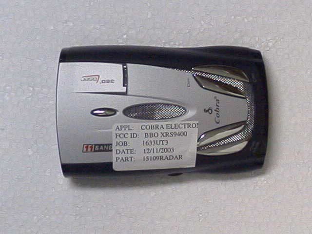
Click to zoom
Application Details
- Equipment Class
- CRD - Part 15 Radar Detector
- Date of Grant
- Dec 30, 2003
- Application Purpose
- Original Equipment
- Date of Application
- Dec 30, 2003
- Equipment Note
- RADAR DETECTOR
- Frequency Range
- 33400.00000000 - 36000.00000000
- Country
- United States
Documents & Files
Document Text
Text extracted from the exhibit documents filed with the FCC. Open a document above to read the original.
Users Manual
Important Information And Customer Assistance Introduction A1 English Important Information • Federal Laws Governing The Use Of Radar Detectors It is not against federal law to receive radar transmissions with your Cobra radar/laser detector. The Communications Act of 1924 guarantees your right to receive radio transmissions on any frequency. Local laws that contravene this Act, while illegal, may be enforced by your local law enforcement officials until and unless they are prohibited from doing so by federal court action.Safety AlertUse of this product is not intended to, and does not, ensure that motorists orpassengers will not be involved in traffic accidents. It is only intended to alert the motorist that an emergency vehicle equipped with a Cobra Safety Alert transmitter is within range as defined by that product. Please call local fire and police departments to learn if coverage exists in your area.Safe Driving Motorists, as well as operators of emergency or service vehicles, are expected toexercise all due caution while using this product, and to obey all applicable traffic laws.Security Of Your Vehicle Before leaving your vehicle, always remember to conceal your radar detector in order to reduce the possibility of break-in and theft.Customer Assistance • Should you encounter any problems with this product, or not understand its many features,please refer to this owner’s manual. If you require further assistance after reading thismanual, Cobra Electronics offers the following customer assistance services:For Assistance In The U.S.A. Automated Help Desk English only. 24 hours a day, 7 days a week 773-889-3087 (phone). Customer Assistance Operators English and Spanish. 8:00 a.m. to 6:00 p.m. CT Mon. through Fri. (except holidays) 773-889-3087 (phone).Questions English and Spanish. Faxes can be received at 773-622-2269 (fax). T echnical Assistance English only. www .cobra.com (on-line: Frequently Asked Questions). English and Spanish. [email protected] (e-mail).For Assistance Outside The U.S.A. Contact Your Local Dealer XRS 9300 11 BAND ™ HIGH-PERFORMANCE RADAR/LASER DETECTOR WITH XTREME RANGE SUPERHETERODYNE ™ TECHNOLOGY Nothing comes close to a Cobra ® English Nothing comes close to a Cobra ® English Operating Instructions Printed in China Part No. 480-103-P For more information or to order any of our products, please visit our website: www.cobra.com © 2003 Cobra Electronics Corporation 6500 West Cortland Street Chicago, Illinois 60707 USA www.cobra.com CB RadiosmicroTALK ® Radios Radar/Laser Detectors Safety Alert ® T raffic Warning Systems Accessories GPS (Global Positioning System)HighGear ® Accessories VHF Marine Radios Power Inverters The Cobra line of quality products includes: Customer Assistance 9300-3b-Cover 12/4/03 10:07 AM Page 1 Order Form Nothing comes close to a Cobra ® 25 Order Form • NameAddress (No P.O. Boxes)City State/Province Zip Country T elephone Credit Card Number Type: ❒ V isa ❒ MasterCard ❒ Discover Exp. Date Customer Signature Item # Description U.S. Cost Each Qty Amount 420-030-N-001 Straight 12V Power Cord 420-026-N-001 Coiled 12V Power Cord 545-139-N-001 Windshield Mounting Bracket CLP-2B Dual Port Power Adapter U.S. Subtotal (Tax if Applicable) Shipping/Handling T otal Ordering From U.S.A.Call 773-889-3087 for pricing or visit www.cobra.com.For Credit Card OrdersComplete and return this order form to fax number 773-622-2269. Or call 773-889-3087[Press one (1) from the main menu] 8:00 a.m. to 6:00 p.m. CT, Monday through Friday.Make Check or Money Order Payable ToCobra Electronics, Attn: Accessories Dept., 6500 West Cortland Street, Chicago, IL 60707 U.S.A.To Order Online Please visit our website: www.cobra.com Amount Shipping/Handling*$10.00 or less . . . . . $3.00$10.01-$25.00 . . . . . $5.50$25.01-$50.00 . . . . . $7.50$50.01-$90.00 . . . . $10.50$90.01-$130.00 . . . $13.50$130.01-$200.00 . . $16.50$200.01 plus . . . . . 10% of purchase T ax Table Wisconsin add 5%Indiana, Michigan, Ohio add 6%California add 7.25%Illinois add 8.75% * For AK, HI and PR add additional $26.95 for FedEx Next Day or $10.95 for FedEx 2nd Day. Excludes weekends and holidays shipments. Please allow two (2) to three (3) weeks for delivery in the U.S.A. Prices subject to change without notice. Display And Product Features Introduction Nothing comes close to a Cobra ® A3 Controls, IndicatorsAnd Connections Introduction A2 English Xtreme Range Superheterodyne TechnologyWith super-fast sweep circuitry, XRS provides extra detection range and the best possible advance warning to even the fastest radar gunsDetection And Separate Alerts For: Radar signals (X, K and Ka bands, with signal strength indicated), laser signals, Safety Alert signals, Strobe Alert signals, VG-2 signals,Spectre 1 signalsLaserEye For 360° detection of laser and strobe signalsInstant-On Ready Detects radar guns with “instant-on”(very fast) speed monitoring capabilitiesT one Alerts With adjustable volume UltraBright Data Display Easy-to-read with adjustable brightnessCity Or Highway Modes to reduce false alertsSafety Alert T raffic warning system distinguishes important safety alerts from other K band signalsStrobe AlertEmergency vehicle warning systemManual Mute Or Auto Mute A mute function of audio alertsIntelliMute A mute function which automatically reduces false alerts by sensing engine RPMsMounting Mounts easily on windshield or dashboard Product Features • Congratulations! You’ve made a smart choice by purchasing the XRS 9300high performance radar/laser detector from Cobra. Just look at some of thesophisticated features and capabilities your new unit includes: Controls, Indicators And Connections • Display • This booklet describes the simple steps for mounting and setting up your detector. It also provides helpful information about how radar and laser guns are used and how you can interpret the alerts you receive. 12V DCPower Jack On-Off/ V olume Control Allows you to adjust the volume of the tone aler…
Text truncated - open the document above for the full version.
Cover Letter(s)
December 11, 2003 Federal Communications Commission Authorization and Evaluation Division Confidentiality Request; FCC ID: BBOXRS9400 Pursuant to Sections 0.457 ands 0.459 of the Commission’s Rules, the Applicant hereby requests confidential treatment of information accompanying this Application as outlined below: Schematics Block Diagrams Operational Descriptions The above materials contain trade secrets and proprietary information not customarily released to the public. The public disclosure of these matters might be harmful to the Applicant and provide unjustified benefits to its competitors. The Applicant understands that pursuant to Rule 0.457, disclosure of this Application and all accompanying documentation will not be made before the date of the Grant for this application. Sincerely, Jeff Sterling Director – Microwave Engineering Cobra Electronics Corp.
Test Report
TIMCO ENGINEERING INC. 849 NW State Road 45 Newberry, Florida 32669 http://www.timcoengr.com 888.472.2424 F 352.472.2030 email: [email protected] APPLICANT: COBRA ELECTRONICS CORPORATION Test Report Product Name: RADAR DETECTOR FCC ID: BBOXRS9400 Applicant: COBRA ELECTRONICS CORPORATION 6500 WEST CORTLAND STREET CHICAGO, IL 60707 Date Receipt: DECEMBER 11, 2003 Date Tested: DECEMBER 29, 2003 FCC ID: BBOXRS9400 REPORT #: C\COBRA\1633UT3\1633UT3TestReport.doc COVER PAGE TIMCO ENGINEERING INC. 849 NW State Road 45 Newberry, Florida 32669 http://www.timcoengr.com 888.472.2424 F 352.472.2030 email: [email protected] APPLICANT: COBRA ELECTRONICS CORPORATION TABLE OF CONTENTS LIST APPLICANT: COBRA ELECTRONICS CORPORATION FCC ID: BBOXRS9400 TEST REPORT CONTAINING: PAGE 1......TEST EQUIPMENT LIST PAGE 2-3....TEST PROCEDURES PAGE 4......RADIATION INTERFERENCE TEST DATA PAGE 5......HORIZONTAL MEASUREMENT PLOT PAGE 6......VERTICAL MEASURMENT PLOT EXHIBITS CONTAINING: EXHIBIT 1............CONFIDENTIALITY LETTER EXHIBIT 2............BLOCK DIAGRAM EXHIBIT 3............SCHEMATIC EXHIBIT 4............USERS MANUAL EXHIBIT 5............LABEL SAMPLE EXHIBIT 6............LABEL LOCATION EXHIBIT 7............EXTERNAL PHOTOGRAPHS EXHIBIT 8............INTERNAL PHOTOGRAPHS EXHIBIT 9............CIRCUIT DESCRIPTION EXHIBIT 10...........TEST SET UP PHOTOGRAPH FCC ID: BBOXRS9400 REPORT #: C\COBRA\1633UT3\1633UT3TestReport.doc TABLE OF CONTENTS TIMCO ENGINEERING INC. 849 NW State Road 45 Newberry, Florida 32669 http://www.timcoengr.com 888.472.2424 F 352.472.2030 email: [email protected] APPLICANT: COBRA ELECTRONICS CORPORATION Equipment List Device Manufacturer Model Serial Number Cal/Char Date Due Date 3/10-Meter OATS TEI N/A N/A Listed 3/26/01 3/26/04 3-Meter OATS TEI N/A N/A Listed 1/13/03 1/13/06 Biconnical Antenna Eaton 94455-1 1057 CAL 3/18/03 3/18/05 Biconnical Antenna Eaton 94455-1 1096 CAL 10/1/01 10/1/03 Biconnical Antenna Electro- Metrics BIA-25 1171 CAL 4/26/01 4/26/03 Log-Periodic Antenna Eaton 96005 1243 CAL 5/8/03 5/8/05 FCC ID: BBOXRS9400 REPORT #: C\COBRA\1633UT3\1633UT3TestReport.doc Page 1 of 6 TIMCO ENGINEERING INC. 849 NW State Road 45 Newberry, Florida 32669 http://www.timcoengr.com 8.472.2424 F 352.472.2030 email: [email protected] 88 APPLICANT: COBRA ELECTRONICS CORPORATION FCC ID: BBOXRS9400 REPORT #: C\COBRA\1633UT3\1633UT3TestReport.doc Page 2 of 6 TEST PROCEDURES GENERAL: This report shall NOT be reproduced except in full without the written approval of TIMCO ENGINEERING, INC. RADIATION INTERFERENCE: Testing was done in accordance with ANSI C63.4-2001. Section 15.35(b) specifies the use of an average detector in this band. In addition, the peak level of an emission shall not exceed the average limit by more than 20 dB using a minimum Resolution Bandwidth (RBW) of 1 MHz and minimum Video Bandwidth (VBW) OF 1 MHz. The following procedure is designed to determine if there are any spurious emissions from the local oscillator within the band of interest along with any additional spurious emissions caused by other circuitry within the device. 1) Determine the frequency of the peak emission: Start Frequency 11.7 GHz Stop Frequency 12.2 GHz RBW equal to or greater than 1 MHz VBW equal to or greater than 1 MHz Detector Function Peak Maximize the emissions with regards to device orientation, antenna polarization, and antenna height. Sweep the band using Max Hold for a minimum of 2 minutes. Record this frequency for measuring the peak emission. In addition record the frequency of other spurious emissions noted. 2) Determine the peak level of the emission: Center Frequency Set to the frequency determined in Step 1 RBW Equal to or greater than 1 MHz VBW Equal to or greater than 1 MHz Detector Function Peak Measure the value of the peak emission using Max Hold for a minimum of 2 minutes. This can be done at zero span or a frequency span where the analyzer does not show a “Measurement Uncalibrated” message. Record the peak value. If the peak measurement is compliant with the average limit an average measurement is not necessary. If the peak value exceeds the average limit by less than 20 dB proceed to Step 3. 3) Determine the average level of the emission: Center Frequency Set to the frequency determined in Step 1 Span Zero RBW Equal to or greater than 1 MHz VBW Equal to or greater than 10 Hz Detector Function Peak This measurement uses video averaging and must be done in Linear mode. The analyzer Reference Level is adjusted so that a signal is clearly visible on the screen. Measure the value of the emission using Max Hold for a minimum of 2 minutes. Record this as the average value. Step 2 and Step 3 should be repeated for other spurious emissions. The ambient temperature of the UUT was 80ºF with a humidity of 70%. TIMCO ENGINEERING INC. 849 NW State Road 45 Newberry, Florida 32669 http://www.timcoengr.com 888.472.2424 F 352.472.2030 email: [email protected] APPLICANT: COBRA ELECTRONICS CORPORATION TEST PROCEDURES CONTINUED FORMULA OF CONVERSION FACTORS: The Field Strength at 3m was established by adding the meter reading of the spectrum analyzer (which is set to read in units of dBuV) to the antenna correction factor supplied by the antenna manufacturer. The antenna correction factors are stated in terms of dB. The gain of the Preselector was accounted for in the Spectrum Analyzer Meter Reading. Example: Freq (MHz) METER READING + ACF = FS 33 20 dBuV + 10.36 dB = 30.36 dBuV/m @ 3m ANSI STANDARD C63.4-1992 10.1.7 MEASUREMENT PROCEDURES: The unit under test was placed on a table 80 cm high and with dimensions of 1m by 1.5m. The table used for radiated measurements is capable of continuous rotation. When an emission was found, the table was rotated to produce the maximum signal strength. At this point, the antenna was raised and lowered from 1m to 4m. The antenna was placed in both the horizontal and vertical planes. FCC ID: BBOXRS9400 REPORT #: C\COBRA\1633UT3\1633UT3TestReport.doc Page 3 of 6 TIMCO ENGI…
Text truncated - open the document above for the full version.
Contact Information
Applicant
Chris de Waal(Senior Project Engineer)
Test Firm
Timco Engineering, Inc.S Sanders
Technical Specifications
| # | Rule Parts | Frequency Range | Power Output |
|---|---|---|---|
| 3 | 15B | 33.40 GHz - 36.00 GHz | - |
Other Applications from Cobra Electronics Corporation
BBOCHEM01
Jul 21, 2026Radar detector
Equipment Class
CRD - Part 15 Radar DetectorBBOPERF600
Jul 13, 2026PERFORMA 600 RADIO DIGITAL BULK, US/COBRA PERFORMA 600 DIGITAL SINGLE PACK, US/COBRA PERFORMA 600 DIGITAL SIX PACK, US/COBRA PERFORMA 600 DIGITAL RADIO, US
Equipment Class
TNF - Licensed Non-Broadcast Transmitter Held to Face
BBOBB650
May 01, 2026VHF Marine Radio Transceiver
Equipment Class
TNF - Licensed Non-Broadcast Transmitter Held to FaceBBOLESS01
Apr 14, 2026Radar detector with Bluetooth
Equipment Class
DTS - Digital Transmission System
BBOCBPT01
Feb 14, 2023Wireless PTT
Equipment Class
DTS - Digital Transmission System