BEJ9QK-DMPWMN5275WLAN Adapter Card
LG Electronics USA, Inc.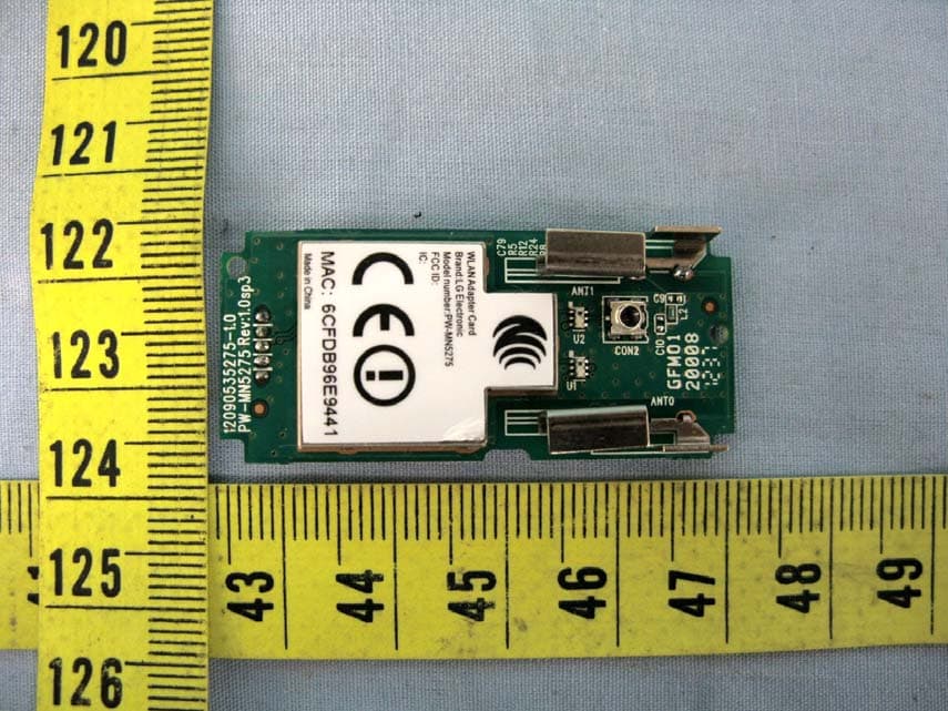
Click to zoom
Application Details
- Equipment Class
- NII - Unlicensed National Information Infrastructure TX
- Date of Grant
- Oct 31, 2012
- Application Purpose
- Original Equipment
- Date of Application
- Oct 31, 2012
- Equipment Note
- WLAN Adapter Card
- Frequency Range
- 5180.00000000 - 5240.00000000
- Company
- LG Electronics USA, Inc.
- Country
- United States
Documents & Files
Document Text
Text extracted from the exhibit documents filed with the FCC. Open a document above to read the original.
Users Manual
19-1, Cheongho-ri Jinwi-myeon, Pyeongtaek-si,Gyeonggi-do, 451-713, Korea PW-MN5275 WLAN Adapter Card User Guide Version 1.1 OCT., 2012 19-1, Cheongho-ri Jinwi-myeon, Pyeongtaek-si,Gyeonggi-do, 451-713, Korea Revision History Release Date Revision Initials 1.1 2012-10-31 First release. 19-1, Cheongho-ri Jinwi-myeon, Pyeongtaek-si,Gyeonggi-do, 451-713, Korea STATEMENT and Warning This device complies with Part 15 of the FCC Rules. Operation is subject to the following two conditions: (1) This device may not cause harmful interference, and (2) this device must accept any interference received, including interference that may cause undesired operation. FCC Caution: Any changes or modifications not expressly approved by the party responsible for compliance could void the user's authority to operate this equipment. This transmitter must not be co-located or operating in conjunction with any other antenna or transmitter. 5150-5250MHz is limited “indoor use only” . FCC RF Radiation Exposure Statement This equipment complies with FCC radiation exposure limits set forth for an uncontrolled environment. This equipment should be installed and operated with minimum distance 20cm between the radiator & your body. IC This device complies with Industry Canada license-exempt RSS standard(s). Operation is subject to the following two conditions: (1) this device may not cause interference, and (2) this device must accept any interference, including interference that may cause undesired operation of the device. This equipment complies with IC radiation exposure limits set forth for an uncontrolled environment. This equipment should be installed and operated with minimum distance 20cm between the radiator and your body. French: Cet appareil radio est conforme au CNR-210 d’Industrie Canada. L’utilisation de ce dispositif est autorisée seulement aux deux conditions suivantes : (1) il ne doit pas produire de brouillage, et (2) l’utilisateur du dispositif doit être prêt à accepter tout brouillage radioélectrique reçu, même si ce brouillage est susceptible de compromettre le fonctionnement du dispositif. Cet équipement est conforme aux limites d’exposition aux rayonnements IC établies pour un environnement non contrôlé. Cet équipement doit être installé et utilisé avec un minimum de 20 cm de distance entre la source de rayonnement et votre corps. 19-1, Cheongho-ri Jinwi-myeon, Pyeongtaek-si,Gyeonggi-do, 451-713, Korea Japan NCC 「依據低功率電波輻射性電機管理辦法 第十二條 經型式認證合格之低功率射頻電機,非經許可,公司、商號或使用者均 不得擅自變更頻率、加大功率或變更原設計之特性及功能。 第十四條 低功率射頻電機之使用不得影響飛航安全及干擾合法通信;經發現有干 擾現象時,應立即停用,並改善至無干擾時方得繼續使用。 前項合法通信,指依電信法規定作業之無線電通信。 低功率射頻電機須忍受合法通信或工業、科學及醫療用電波輻射性電機 設備之干擾。」 任一平台若裝置本模組,其平台標籤須標示 “內建WiFi模組 NCC:XXXXXXXXXXX” This device is intended only for OEM integrators under the following conditions: The antenna must be installed such that 20 cm is maintained between the antenna and users, and The transmitter module may not be co-located with any other transmitter or antenna. As long as 2 conditions above are met, further transmitter test will not be required. However, the OEM integrator is still responsible for testing their end-product for any additional compliance requirements required with this module installed IMPORTANT NOTE: In the event that these conditions can not be met (for example certain laptop configurations or co-location with another transmitter), then the FCC authorization is no longer considered valid and the FCC ID cannot be used on the final product. In these circumstances, the OEM integrator will be responsible for re-evaluating the end product (including the transmitter) and obtaining a separate FCC authorization. 19-1, Cheongho-ri Jinwi-myeon, Pyeongtaek-si,Gyeonggi-do, 451-713, Korea End Product Labeling This transmitter module is authorized only for use in device where the antenna may be installed such that 20 cm may be maintained between the antenna and users. The final end product must be labeled in a visible area with the following: “Contains FCC ID: BEJ9QK-DMPWMN5275”, “contains IC: 2703H-DMPWMN5275”. The grantee's FCC ID can be used only when all FCC/ IC compliance requirements are met. Manual Information To the End User The OEM integrator has to be aware not to provide information to the end user regarding how to install or remove this RF module in the user’s manual of the end product which integrates this module. CE Hereby declares that this WiFi module is in compliance with the essential requirements and other relevant provisions of R&TTE Directive 1999/5/EC. The standards for complying are as following: ETSI EN 301 489-1 V1.9.2: 2011-09 ETSI EN 301 489-17 V2.1.1: 2009-05 ETSI EN 300 328 V1.7.1:2006-10 ETSI EN 301 893 V1.6.1: 2011-11 EN 62311: 2008 EN 60950-1: 2006 +A11:2009 This is a class B product. In a domestic environment, this product may cause radio interference, in which case the user may be required to take adequate measures. This is a class B product. In a domestic environment, this product may cause radio interference, in which case the user may be required to take adequate measures. National Restrictions This device is intended for home and office use in all EU countries (and other countries following the EU directive 1999/5/EC) without any limitation except for the countries mentioned below: 19-1, Cheongho-ri Jinwi-myeon, Pyeongtaek-si,Gyeonggi-do, 451-713, Korea Country Restriction Reason/remark Bulgaria None General authorization required for outdoor use and public service Italy None If used outside of own premises, general authorization is required Luxembourg None General authorization required for network and service supply(not for spectrum) Norway Implemented This subsection does not apply for the geographical area within a radius of 20 km from the centre of Ny-Ålesund Russian Federation None Only for indoor applications To reduce potential radio interference to other users, the antenna type and its gain should be so chosen that the equivalent is tropically radiated power (e.i.r.p.) is not more than …
Text truncated - open the document above for the full version.
Cover Letter(s)
Date: 2012/11/1 Federal Communications Commission 7435 Oakland Mills Road Columbia MD 21046 Modular Approval Request Letter AUDIX Technology Corporation. Aug. 15, 2012 Dear Application Examiner, The WLAN Adapter Card, modem name is PW-MN5275, FCC ID: BEJ9QK-DMPWMN5275 , would like to have your authorization as a modular approval specific to the mobile device such as digital device emissions, The requirements of Public Notice DA00-1407 have been met and shown on the following statements. 1. “The modular transmitter must have its own RF shielding.”: Yes, the radio portion of this module has been shielded, please see exhibition External Photo. 2. “The modular transmitter must have buffered modulation/data inputs.” Yes, he buffer is invisible for embedding in chip. 3. “The modular transmitter must have its own power supply regulation.” Yes, the EUT has its’ own power supply regulation. 4. “The modular transmitter must comply with the antenna requirements of section 15.203 and 15.204(C).” Yes, the EUT meets the FCC antenna requirements. The spurious emission, the antenna is PCB antenna and intergrated. 5. “The modular transmitter must be tested in a stand-alone configuration” Yes, the EUT was tested in a stand-alone configuration via an USB cable. Please see section Photographs of Test Configuration in the test report. 6. “The modular transmitter must be labeled with its own FCC ID number.” Yes, this module has been labeled with its’ own FCC ID number. Please see exhibition Label Sample for the FCC ID of this module. And also in the exhibition Users Manual, there are instructions give to the OEM on how to label the end product. 7. “The modular transmitter must comply with any specific rule or operating requirements applicable to the transmitter and the manufacturer must provide adequate instructions along with the module to explain any such requirements.” Yes, the EUT is compliant with all applicable FCC rules. Detail instructions for maintaining compliance are given in the Users Manual. 8. “The modular transmitter must comply with any applicable RF exposure requirements.” Yes, the EUT is compliant with all applicable RF exposure requirements. RF Exposure is addressed in the RF exposure exhibition. Sincerely Yours, ____________________________________ Mr. Ben Cheng Manager AUDIX Technology Corporation
External Photos
LG Electronics Inc. WLAN Adapter Card FCC ID. : BEJ9QK-DMPWMN5275 IC: 2703H-DMPWMN5275 EUT External Photos Figure 1 WLAN Adapter Card (Front View) Figure 2 WLAN Adapter Card (Front View) LG Electronics Inc. WLAN Adapter Card FCC ID. : BEJ9QK-DMPWMN5275 IC: 2703H-DMPWMN5275 Figure 3 WLAN Adapter Card (Back View)
ID Label/Location Info
LG Electronics Inc. WLAN Adapter Card FCC ID. : BEJ9QK-DMPWMN5275 IC: 2703H-DMPWMN5275 FCC ID & IC Label Location z Label Placement Location z FCC ID & IC Label Format FCC ID & IC Label Placement Location
Internal Photos
LG Electronics Inc. WLAN Adapter Card FCC ID. : BEJ9QK-DMPWMN5275 IC: 2703H-DMPWMN5275 EUT External Photos Figure 1 WLAN Adapter Card (Front View) Figure 2 WLAN Adapter Card (Front View) LG Electronics Inc. WLAN Adapter Card FCC ID. : BEJ9QK-DMPWMN5275 IC: 2703H-DMPWMN5275 Figure 3 WLAN Adapter Card (Back View)
RF Exposure Info
Maximum Permissive Exposure FCC ID: BEJ9QK-DMPWMN5275 Product Name: WLAN Adapter Card Model No: PW-MN5275 We, hereby clarify that BEJ9QK-DMPWMN5275 is applied for single modular approval, and this model might be embedded with Bluetooth device. Thus, this MPE takes collocation into consideration as the worst case for demonstrating is compliance with requirement. 1. According to FCC CFR 47 §1.1310, the criteria listed in the following table shall be used to evaluate the environmental impact of human exposure to radio frequency (RF) radiation as specified in 1.1307(b). Table 1 Limits for Maximum Permissible Exposure 2. MPE Calculation For WLAN(2.4GHz): Based on safety distance 20cm, the antenna gain is 4.35dBi, and the power output is 217.27mW,the power density is0.01177mW/cm^2. RF Exposure Calculations: S = (P * G) / (4* π * r^2) or r = (P * G) / (4 * π * S) Where S = Power Density in mW/cm^2 P=23.37dBm=217.27mw G =4.35dBi=2.723Numerical r = 20cm S = 7.27*2.723/ 4*π* 20^2 =0.1177mW/cm^ For WLAN(5.2GHz): Based on safety distance 20cm, the antenna gain is 4.86dBi, and the power output is 21.777mW,the power density is 0.0089mW/cm^2. RF Exposure Calculations: S = (P * G) / (4* π * r^2) or r = (P * G) / (4 * π * S) Where S = Power Density in mW/cm^2 P = 13.38dBm= 21.777mW G = 4.86dBi =3.062Numerical r = 20cm S = 21.777*3.062 / 4*π* 20^2 = 0.0132mW/cm^2 For WLAN(5.8GHz): Based on safety distance 20cm, the antenna gain is 4.64dBi, and the power output is 87.70mW,the power density is 0.0507mW/cm^2. RF Exposure Calculations: S = (P * G) / (4* π * r^2) or r = (P * G) / (4 * π * S) Where S = Power Density in mW/cm^2 P = 19.43dBm =87.70mW G = 4.64dBi =2.911 Numerical r = 20cm S = 87.70* 2.911/ 4*π* 20^2 =0.0507mW/cm^2 For Bluetooth: Based on safety distance 20cm, the allowed maximum antenna gain is 6dBi, and the power output of class 1BT device is 100 mW,the power density is 0.079mW/cm^2. RF Exposure Calculations: S = (P * G) / (4* π * r^2) or r = (P * G) / (4 * π * S) Where S = Power Density in mW/cm^2 P = 20dBm = 100mW G = 6dBi = 3.98 Numerical r = 20cm S = 290.40*1.242 / 4*π* 20^2 = 0.079mW/cm^2 Bluetooth MPE (mW/cm^2) WLAN MPE (mW/cm^2) Total MPE (mW/cm^2) Limit (mW/cm^2) Compliance or not 0.079 0.01177 0.09077 1 YES Sincerely Yours, ____________________________________ Mr. Ben Cheng Manager AUDIX Technology Corporation
Test Report
FCC ID: BEJ9QK-DMPWMN5275 IC: 2703H-DMPWMN5275 Page 1 of 63 AUDIX Technology Corporation Report No. EM-F1010831 APPLICATION FOR CERTIFICATION On Behalf of LG Electronics Inc. WLAN Adapter Card Model No.PW-MN5275 FCC ID : BEJ9QK-DMPWMN5275 IC: 2703H-DMPWMN5275 Brand : LG Prepared for : LG Electronics Inc. 19-1, Cheongho-Ri, Jinwuy-Myeon, Pyeongtaek-City, Gyeonggi-Do, 451-713, Korea Prepared by : AUDIX Technology Corporation EMC Department No. 53-11, Dingfu, Linkou Dist., New Taipei City 244, Taiwan, R.O.C. Tel : (02) 2609-9301, 2609-2133 Fax: (02) 2609-9303 File Number C1M1210175 Report Number EM-F1010831 Date of Test Oct. 15 ~ 22, 2012 Date of Report Oct. 23, 2012 FCC ID: BEJ9QK-DMPWMN5275 IC: 2703H-DMPWMN5275 Page 2 of 63 AUDIX Technology Corporation Report No. EM-F1010831 TABLE OF CONTENTS Description Page TEST REPORT CERTIFICATION .......................................................................................................4 1. GENERAL INFORMATION .........................................................................................................5 1.1. Description of Device (EUT).................................................................................................................. 5 1.2. Data Rate Relative to Output Power....................................................................................................... 6 1.3. Test Configuration for Each Test Item ................................................................................................... 6 1.4. Tested Supporting System Details .......................................................................................................... 7 1.5. Description of Test Facility .................................................................................................................... 7 1.6. Measurement Uncertainty....................................................................................................................... 8 2. CONDUCTED EMISSION MEASUREMENT ............................................................................9 2.1. Test Equipment ....................................................................................................................................... 9 2.2. Block Diagram of Test Setup.................................................................................................................. 9 2.3. Powerline Conducted Emission Limit [§15.207, Class B, RSS-Gen §7.2.2/Table 2] ......................... 9 2.4. Operating Condition of EUT ................................................................................................................ 10 2.5. Test Procedure ...................................................................................................................................... 10 2.6. Powerline Conducted Emission Measurement Results......................................................................... 10 3. RADIATED EMISSION MEASUREMENT ..............................................................................13 3.1. Test Equipment ..................................................................................................................................... 13 3.2. Test Setup ............................................................................................................................................. 13 3.3. Radiated Emission Limits ..................................................................................................................... 15 3.4. Operating Condition of EUT ................................................................................................................ 15 3.5. Test Procedure ...................................................................................................................................... 16 3.6. Test Results........................................................................................................................................... 17 4. 26dB BANDWIDTH MEASUREMENT .....................................................................................34 4.1. Test Equipment ..................................................................................................................................... 34 4.2. Block Diagram of Test Setup................................................................................................................ 34 4.3. Operating Condition of EUT ................................................................................................................ 34 4.4. Test Procedure ...................................................................................................................................... 34 4.5. Test Results........................................................................................................................................... 35 5. MAXIMUM PEAK OUTPUT POWER MEASUREMENT .....................................................40 5.1. Test Equipment ..................................................................................................................................... 40 5.2. Block Diagram of Test Setup................................................................................................................ 40 5.3. Specification Limits [§15.407(a)-(1), RSS-210 A9.2 (1)] .................................................................... 40 5.4. Operating Condition of EUT ................................................................................................................ 40 5.5. Test Procedure ...................................................................................................................................... 41 5.6. Test Results........................................................................................................................................... 41 6. POWER SPECTRAL DENSITY MEASUREMENT ................................................................42 6.1. Test Equipment …
Text truncated - open the document above for the full version.
Test Setup Photos
FCC ID: BEJ9QK-DMPWMN5275 IC: 2703H-DMPWMN5275 Page 61 of 63 AUDIX Technology Corporation Report No. EM-F1010831 10. PHOTOGRAPHS 10.1. Photos of Conducted Emission Measurement FRONT VIEW OF CONDUCTED MEASUREMENT BACK VIEW OF CONDUCTED MEASUREMENT FCC ID: BEJ9QK-DMPWMN5275 IC: 2703H-DMPWMN5275 Page 62 of 63 AUDIX Technology Corporation Report No. EM-F1010831 10.2. Photos of Radiated Measurement at Semi-Anechoic Chamber 10.2.1.Frequency Below 1GHz 10.2.2. Frequency Above 1GHz FCC ID: BEJ9QK-DMPWMN5275 IC: 2703H-DMPWMN5275 Page 63 of 63 AUDIX Technology Corporation Report No. EM-F1010831 10.3. Photo of Section RF Conducted Measurement 10.4. Photo of Maximum Peak Output Power Measurement
Contact Information
Applicant
David Kim(Team leader, LGEUS NA Policy & Regulatory Affairs)
Technical Contact
AUDIX Technology CorporationBen Cheng
No. 53-11, Dingfu, Linkou Dist., · New Taipei City · Taiwan
Test Firm
Audix Technology CorporationLeon Liu
Technical Specifications
| # | Rule Parts | Frequency Range | Power Output |
|---|---|---|---|
| 1 | 15E | 5.18 GHz - 5.24 GHz | 21.77 mW |
Other Applications from LG Electronics USA, Inc.

BEJTFHOBINI1F1
Jan 08, 2025Telematics
Equipment Class
DTS - Digital Transmission SystemBEJNT-16Z90TS
Oct 02, 2024Notebook Computer
Equipment Class
DSS - Part 15 Spread Spectrum TransmitterBEJSP-PEW8
Sep 26, 2024Stylus Pen
Equipment Class
DCD - Part 15 Low Power Transmitter Below 1705 kHzBEJ-RSMV2
Sep 24, 2024RF Module
Equipment Class
FDS - Part 15 Field Disturbance SensorBEJTFBMEIBN3EU
Sep 24, 2024Telematics
Equipment Class
NII - Unlicensed National Information Infrastructure TX