BEJAD5235Single Band CDMA Mobile Phone
LG Electronics USA, Inc.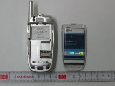
Click to zoom
Application Details
- Equipment Class
- TNE - Licensed Non-Broadcast Transmitter Held to Ear
- Date of Grant
- Jun 20, 2004
- Application Purpose
- Original Equipment
- Date of Application
- Jun 20, 2004
- Equipment Note
- Single Band CDMA Mobile Phone
- Frequency Range
- 824.70000000 - 848.31000000
- Company
- LG Electronics USA, Inc.
- Country
- United States
Documents & Files
Document Text
Text extracted from the exhibit documents filed with the FCC. Open a document above to read the original.
Users Manual
LG-AD5235 User Guide CDMA PHONE Contents Introduction Highlights Important Information Check Accessories Before You Start FCC RF EXPOSURE INFORMATION Chapter 1. Getting Started Cautions Phone Overview On screen Icons Chapter 2. Basic Functions Turning the Phone On and Off Making a Call Correcting Dialing Mistakes Receiving Calls Emergency Dialing Speed Dialing Phone Book Features Chapter 3. Menu Features General Guidelines to MENU Access and Settings Names Messages Record Organiser Fun&Util Profiles Display Settings My Menu Chapter 4. Book Features Names Chapter 5. Message Features Send Msg Inbox Outbox Voice Mail Archive Draft Templates Delete Msg Msg Settings Chapter 6. Functions used during a call Send Number Mute On/Off Find Voice Privacy Key Tones Chapter 7. Accessories Appendix 1. Installation Appendix 2. RF Exposure Statement Chapter 1. Getting Started Cautions ??Using the phone in proximity to receiving equipment (i.e., TV or radio) may cause interference. ??Keep your phone in a safe place when not in use. ??Only use the batteries, antennas, and chargers provided by LG. Using the wrong accessories could void your warranty. ??Only authorized personnel should service the phone and its accessories. Faulty installation or service may result in accidents and consequently invalidate the warranty. ??Do not hold the antenna while the phone is in use. ??Do not use the phone in designated “no cellular phone use” areas. ??Do not expose the phone to high temperature or humidity. ??Avoid getting your phone wet. If the phone gets wet, turn the power off immediately and remove the battery pack. If the phone is mal-functional, return it to the dealer for service. ??Avoid shock or impact on the phone. Phone Overview Function Key Descriptions Lamp The light goes on when you use the power key to turn on the phone and when there are incoming calls and messages. LCD screen Displays messages & indicator icons. END/PWR Used to turn power on/off. This key disconnects a call. Using this key, you can also exit out of a menu back to the phone’s standby display without changing the setting. SEND Allows user to place or answer calls. Mouse Key This mouse key allows quick access to text and voice mail notification messages. Profiles, R- World, and RingTone menu. And these keys are used to scroll through the memory locations and menu items. Alphanumeric Keypad These keys enable you to enter numbers and characters and choose menu items. Soft Keys The current operation of a soft key is defined by the word at the bottom of the display. Soft Keys 2 : If you press this key once in a menu, you can go back one level and if you press and hold the key in a menu, you can go back to the standby display. Side Keys These keys enable you to adjust keybeep volume (in standby mode) and earpiece volume (in a call status). Star/Pound Key - In the standby status, set the manner mode by pressing the [ * ]button. (for 2 seconds) - In the standby status, set the lock function by pressing the [ # ]button. (for 2 seconds) Clear Key This key erase character and In the standby status, you can go MyMenu On screen Icons The phone screen displays several onscreen icons and onscreen icons appears when the phone is power on. Icons Descriptions Displays the strength of the signal received by the phone and current signal strength is indicated as the number of bars displayed on the screen. No service The phone is not receiving a system signal. In use A call is in progress. No icon indicates the phone is in standby mode. Digital indicator Digital service is available. Analog indicator Analog service is unavailable Indicates that a text message or voice mail has been received Roaming The phone is outside of its home service area. Charge level Indicates battery charge level. D Chapter 2. Basic Functions Turning the Phone On and Off Turning the Phone On 1. Install a charged battery pack or connect the phone to an external power source such as the cigarette lighter adapter or car kit. 2. Press [END/PWR] for a few seconds until the red light on the top of the phone flashes. ??Fully extend the antenna for the best performance. <Note> Like any other radio device, avoid any unnecessary contact with the antenna while your phone is on. Turning the Phone Off 1. Press and hold until display screen will be turned off, and then release the key. 2. Protect the antenna by pushing it back into the phone, if extended. Making a Call When you make a call, follow these simple steps: 1. Make sure the phone is turned on. ??If not, press [END/PWR]. 2. Enter the phone number with area code, if needed. 3. Press [SEND]. ??If the phone is locked, enter the lock code. ??“Call Failed” indicates that the call did not go through. 4. Press [END/PWR] to disconnect the call. Correcting Dialing Mistakes If you make mistakes in dialing a number, press [CLR] key once to erase the last entered digit or hold down [CLR] for at least two second to delete all digits. Receiving Calls 1. When the phone rings, open cellcase or If cellcase is open, press any key (except [END/PWR]) to answer. ??If you press the key [END/PWR] once when you receive a call, you can hold the present call and ring sound or vibration stops. If you press the [END/PWR] key twice, the present call is terminated. 2. Press [END/PWR] to disconnect the call. In call waiting mode, the present call is on hold as you answer another incoming call. This service is provided by your service provider. When the call waiting function is activated, your phone will beep to let you know if you have an incoming call. Your phone may also display the incoming caller’s identification. Dialing a call from Phone Book You can place a call from any memory location either by speed dialing or by pressing [SEND] while looking up the memory location. One-Touch Dialing : One-touch dialing is a convenient feature which enables you to dial frequently used numbers in your speed-dial data by pressing a key . ??For locations 1 to 9, you can use one-to…
Text truncated - open the document above for the full version.
Cover Letter(s)
1 Mike Kuo From: Helen Zhao Sent: June212004Monday 2:03 PM To: Mike Kuo Subject: RE: Re : FW: LG Electronics Inc., FCC ID: BEJAD5235, Assessment NO.: AN04T3953 LG-AD5235 Technacal Specificat... LG-AD5235 SAR Test Report.pdf LG-AD5235 User Manual Revised.... Hello Mike, Below is the answer to your questions: Question #1: Only Left/Right head touched and tilted position on channel 363 SAR plots are included in the test report. Please submit all SAR plots for left and right head positions. <Answer> Please see the revised SAR test report. Question #2: Please submit rest of body worn SAR plots. <Answer> Please see the revised SAR test report. Question #3: The transmitting frequency range listed in the test report does not agree with Channel Vs frequency listed in the technical specification file. Please explain. <Answer> Please see the revised Technical Specification. Question #4: Page 15 of user manual, section 2.5.2 Antenna Cable Connection Connect the antenna coupler cable connector from the cradle to the external antenna connector. ( Antenna is not included.) Please explain what type of antenna coupler will be used and how it is connected. Is it connected to the cellular phone ? <Answer> Section 2.5.2 has been removed from the user manual. See the revised manual. Thank you, Helen
Cover Letter(s)
AFFIDAVIT FOR ESN PROTECTION OF CELLULAR MOBILE TELEPHONES We hereby certify that the LGE Handheld Portable Cellular Telephone(FCC ID: BEJAD5235) is so designed that it complies with all the requirements for ESN protection specified in section 22.919 of the FCC Rules. A) The transmitter in service has a unique ESN. B) The ESN host component is permanently attached to a main circuit board of the mobile transmitter and the integrity of the unit operating software cannot be altered. The ESN is plated from fraudulent contact and tampering. The ESN is encoded using multiplication by a polynomial and the ESN data programmed in the memory with other information. C) The ESN is factory-set and cannot be altered, transferred, removed or otherwise able to be manipulated. Cellular mobile equipment is specifically designed such that any attempt to remove, tamper with, or change the ESN chip, its logic system, or firmware originally programmed by the manufacturer will render the mobile transmitter inoperative. Sincerely, E.S.Park Chief Research Engineer CDMA Handset Lab LG Electronics Inc. Tel : 82-2-850-3850 Fax : 82-2-850-3855 [email protected] 459-9, Kasan-dong,Kemchun-ku Seoul 153-023, Korea LG Electronics Inc. LGE
Cover Letter(s)
May 29. 2004 Federal Communication Commission Equipment Authorization Branch 7435 Oakland Mills Road Columbia, MID 21046 In re : LG Electronics Inc.. FCC ID: BEJAD5235 Single - Mode Cellular Phone (CDMA) Part 22 Certification Request for Confidentiality Gentlemen: In accordance with 0.459 of CFR 47, LG Electronics, Inc. hereby requests confidentiality of the Block Diagram, Schematic Diagrams, Operational Description, Technical Specification, Parts List, and Tune-Up Procedure for the above-referenced certification application. These documents contain detailed system and equipment description and related information about the product which LG Electronics Inc. Considers to be proprietary, confidential, and a custom design and, otherwise, would not release to the general public. Since this design is a basis from which future technological products will evolve, LG Electronics Inc. considers this information to be of benefit to its competitors, such that the disclosure of the information in these documents would give competitors an unfair advantage in the market. Sincerely, E.S.Park Chief Research Engineer CDMA Handset Lab LG Electronics Inc. Tel : 82- 2- 850-3850 Fax : 82- 2- 850-3855 [email protected] 459- 9, Kasan-dong,Kemchun-ku Seoul 153- 023, Korea LG Electronics Inc. LGE
External Photos
YVG_ FCC ID : BEJAD5235 Report No.: 00431-4529-C4025 1. External View ZVG_ FCC ID : BEJAD5235 Report No.: 00431-4529-C4025
ID Label/Location Info
PROPOSED FCC ID LABEL AND LOCATION LG ELECTRONICS INC. This device complies with Part 22 of the FCC Rules. FCC ID Label
Internal Photos
[VG_ FCC ID : BEJAD5235 Report No.: 00431-4529-C4025 2. Internal View \VG_ FCC ID : BEJAD5235 Report No.: 00431-4529-C4025 ]VG_ FCC ID : BEJAD5235 Report No.: 00431-4529-C4025 ^VG_ FCC ID : BEJAD5235 Report No.: 00431-4529-C4025 _VG_ FCC ID : BEJAD5235 Report No.: 00431-4529-C4025
RF Exposure Info
SAR Measurement Report Test Date : May 24~25, 2004 FCC ID : BEJAD5235 Test Report No: LGE-SAR2004006 LG ELECTRONICS INC. CDMA HANDSETS LABORATORY MOBILE HANDSETS COMPANY 459-9, Kasan-don, Keumchun -ku Seoul 153-023, Korea TEL: +82-2-850-3860 FAX: +82-2-850-3855www.lge.com - 1/22 - SAR Compliance Test Report APPLICANT NAME & ADDRESS:DATE & LOCATION OF TESTING: LG ELECTRONICS INC. Dates of tests: May 24~25, 2004 Communication Terminal Research Lab Test Site: LG ELECTRONICS, SEOUL Korea 459-9, Kasan-don, Keumchun-ku Seoul 153-023, Korea Attn: S.S. Kim , President Test Device Test Report No. LGE-S A R2004006 Number of Page 70 Contact Person S. S. Kim Responsible Test Engineer E. S. Park Testing has been Carried out in Accordance with IEEE P1528-200X Draft 6.4 Recommended Practice for Determining the Peak Spatial-Average Specific Absorption Rate(SAR) in the Human Body Due to Wireless Communications Device : Experimental Techniques Application Type Certification FCC Classification Licensed Portable Transmitter held to ear (PCE) FCC Rule Part(s) 2.1093; FCC/OET Bu lletin 65 Supplement C (July 2001) Test Results The Tested device complies with the requirements in respect of all parameters subject to the test. The test results and statements relate only to the items tested. The test report shall not be reproduced recept in full, without written approval of the laboratory. Date and Signatures May / 28 / 2004 ReportPrepared by Eui - Soon Park Chief Research Engineer Model : LG-AD5235 FCC ID : BEJAD5235 Type : Single-Mode Single-Band Cellular Phone SAR Measurement Report Test Date : May 24~25, 2004 FCC ID : BEJAD5235 Test Report No: LGE-SAR2004006 LG ELECTRONICS INC. CDMA HANDSETS LABORATORY MOBILE HANDSETS COMPANY 459-9, Kasan-don, Keumchun -ku Seoul 153-023, Korea TEL: +82-2-850-3860 FAX: +82-2-850-3855www.lge.com - 2/22 - Table of Contents 1. SUMMARY FOR SAR TEST REPORT............................................................................................... 3 1.1 Head Configuration ................................................................................................................ 3 1.2 Body Worn Configuration ....................................................................................................... 3 1.3 Measurement Uncertainty ....................................................................................................... 3 2. INTRODUCTION...............................................................................................................................4 3. DESCRIPTION OF THE DEVICE UNDER TEST............................................................................... 5 3.1 Antenna Description................................................................................................................ 5 3.2 Device Description .................................................................................................................. 5 3.3 Battery Option ......................................................................................................................... 5 4. TEST CONDITIONS ......................................................................................................................... 6 4.1 Ambient Conditions.................................................................................................................. 6 4.2 RF Characteristics of The Test Site........................................................................................6 4.3 Test Signal, Frequencies, And Output Power.......................................................................... 6 5. DESCRIPTION OF THE TEST EQUIPMENT.................................................................................... 7 5.1 Test System Specifications..................................................................................................... 7 5.2 SAR Measurement Setup......................................................................................................... 7 5.3 DASY4 E-Field Probe System.................................................................................................8 5.4 Phantom & Equivalent Tissues...............................................................................................10 6. DESCRIPTION OF THE TEST PROCEDURE...................................................................................12 6.1 Definition of Reference Point .................................................................................................12 6.2 Test Configuration Positions..................................................................................................13 6.3 Scan Procedures.....................................................................................................................16 6.4 SAR Averaging Methods.........................................................................................................16 7. MEASUREMENT UNCERTAINTY ...................................................................................................17 8. SYSTEM VERIFICATION.................................................................................................................18 8.1 Tissue Verification.................................................................................................................18 8.2 Test System Validation...........................................................................................................18 9. RESULTS.........................................................................................................................................19 10. REFERENCE..................................................................................................................................22 APPENDIX A : Validation Test Data APPENDIX B : SAR Test Setup Photographs APPENDIX C : SAR Test Data APPENDIX D : Calibration Certificates SAR Measurement Report Test Date : May 24~25, 2004 FCC ID : BEJAD5235 Test Report No: LGE-SAR200…
Text truncated - open the document above for the full version.
RF Exposure Info
SAR Measurement Report Test Date : May 24~25, 2004 FCC ID : BEJAD5235 Test Report No: LGE-SAR2004006 LG ELECTRONICS INC. CDMA HANDSETS LABORATORY MOBILE HANDSETS COMPANY 459-9, Kasan-don, Keumchun -ku Seoul 153-023, Korea TEL: +82-2-850-3860 FAX: +82-2-850-3855 SAR Measurement Report Test Date : May 24~25, 2004 FCC ID : BEJAD5235 Test Report No: LGE-SAR2004006 LG ELECTRONICS INC. CDMA HANDSETS LABORATORY MOBILE HANDSETS COMPANY 459-9, Kasan-don, Keumchun -ku Seoul 153-023, Korea TEL: +82-2-850-3860 FAX: +82-2-850-3855 APPENDIX C : SAR Test Data Test Laboratory: LG Electronics Inc. DUT: LG-AD5230;Type: Single Band-Single Mode;Serial: #1 Program Name: LG-AD5230;CDMA Mode Ch: 1013 Communication System: CDMA;Frequency: 824.7 MHz;Duty Cycle: 1:1 Medium: Head 835 MHz;(σ= 0.89 mho/m; ε r = 40.9; ρ= 1000 kg/m 3 ) Phantom section: Left Section Test Date: 05/24/2004;Ambient Temp: 22.1 C;Tissue Temp: 21.6 C Probe: ET3DV6 - SN1730;ConvF(6.2, 6.2, 6.2);Calibrated: 2003-12-16 Sensor-Surface: 4mm (Mechanical And Optical Surface Detection) Electronics: DAE3 Sn534;Calibrated: 2003-12-23 Phantom: SAM 835;Type: SAM 4.0;Serial: TP-1151 Measurement SW: DASY4, V4.2 Build 44;Postprocessing SW: SEMCAD, V1.8 Build 112 CDMA 1013 Left Head Touch/Area Scan (61x81x1): Measurement grid: dx=15mm, dy=15mm Reference Value = 15.2 V/m; Power Drift = -0.1 dB Maximum value of SAR (interpolated) = 0.894 mW/g CDMA 1013 Left Head Touch/Zoom Scan (7x7x7)/Cube 0: Measurement grid: dx=5mm, dy=5mm, dz=5mm Reference Value = 15.2 V/m; Power Drift = -0.1 dB Maximum value of SAR (measured) = 0.889 mW/g Peak SAR (extrapolated) = 1.18 W/kg SAR(1 g) = 0.82 mW/g; SAR(10 g) = 0.570 mW/g 0 dB = 0.889mW/g Test Laboratory: LG Electronics Inc. DUT: LG -AD5230;Type:Single Band-Single Mode;Serial: #1 Program Name: LG -AD5230;CDMA Mode Ch: 363 Communication System: CDMA;Frequency: 835.89 MHz;Duty Cycle: 1:1 Medium: Head 835 MHz;(σ= 0.89 mho/m;ε r = 40.9;ρ= 1000 kg/m 3 ) Phantom section: Left Section Test Date: 05/24/2004;Ambient Temp: 22.1 C;Tissue Temp: 21.7 C Probe: ET3DV6 - SN1730;ConvF(6.2, 6.2, 6.2);Calibrated: 2003 -12-16 Sensor-Surface: 4mm (Mechanical And Optical Surface Detection) Electronics: DAE3 Sn534;Calibrated: 2003-12-23 Phantom: SAM 835;Type: SAM 4.0;Serial: TP -1151 Measurement SW: DASY4, V4.2 Build 44;Postprocessing SW: SEMCAD, V1.8 Build 112 CDMA 363 Left Head Touch/Area Scan (61x81x1): Measurement grid: dx=15mm, dy=15mm Reference Value = 16 V/m; Power Drift = -0.1 dB Maximum value of SAR (interpolated) = 1.33 mW/g CDMA 363 Left Head Touch/Zoom Scan (7x7x7)/Cube 0: Measurement grid: dx=5mm, dy=5mm, dz=5mm Reference Value = 16 V/m; Power Drift = -0.1 dB Maximum value of SAR (measured) = 1.23 mW/g Peak SAR (extrapolated) = 1.68 W/kg SAR(1 g) = 1.15 mW/g; SAR(10 g) = 0.780 mW/g 0 dB = 1.23mW/g Test Laboratory: LG Electronics Inc. DUT: LG-AD5230;Type: Single Band-Single Mode;Serial: #1 Program Name: LG-AD5230;CDMA Mode Ch: 777 Communication System: CDMA;Frequency: 848.31 MHz;Duty Cycle: 1:1 Medium: Head 835 MHz;(σ= 0.89 mho/m; ε r = 40.9; ρ= 1000 kg/m 3 ) Phantom section: Left Section Test Date: 05/24/2004;Ambient Temp: 22.1 C;Tissue Temp: 21.7 C Probe: ET3DV6 - SN1730;ConvF(6.2, 6.2, 6.2);Calibrated: 2003-12-16 Sensor-Surface: 4mm (Mechanical And Optical Surface Detection) Electronics: DAE3 Sn534;Calibrated: 2003-12-23 Phantom: SAM 835;Type: SAM 4.0;Serial: TP-1151 Measurement SW: DASY4, V4.2 Build 44;Postprocessing SW: SEMCAD, V1.8 Build 112 CDMA 777 Left Head Touch/Area Scan (61x81x1): Measurement grid: dx=15mm, dy=15mm Reference Value = 15.6 V/m; Power Drift = -0.1 dB Maximum value of SAR (interpolated) = 1.19 mW/g CDMA 777 Left Head Touch/Zoom Scan (7x7x7)/Cube 0: Measurement grid: dx=5mm, dy=5mm, dz=5mm Reference Value = 15.6 V/m; Power Drift = -0.1 dB Maximum value of SAR (measured) = 1.08 mW/g Peak SAR (extrapolated) = 1.45 W/kg SAR(1 g) = 1.02 mW/g; SAR(10 g) = 0.693 mW/g 0 dB = 1.08mW/g Test Laboratory: LG Electronics Inc. DUT: LG -AD5230;Type:Single Band-Single Mode;Serial: #1 Program Name: LG -AD5230;CDMA Mode Ch: 363 Communication System: CDMA;Frequency: 835.89 MHz;Duty Cycle: 1:1 Medium: Head 835 MHz;(σ= 0.89 mho/m;ε r = 40.9;ρ= 1000 kg/m 3 ) Phantom section: Left Section Test Date: 05/24/2004;Ambient Temp: 22.3 C;Tissue Temp: 21.8 C Probe: ET3DV6 - SN1730;ConvF(6.2, 6.2, 6.2);Calibrated: 2003 -12-16 Sensor-Surface: 4mm (Mechanical And Optical Surface Detection) Electronics: DAE3 Sn534;Calibrated: 2003-12-23 Phantom: SAM 835;Type: SAM 4.0;Serial: TP -1151 Measurement SW: DASY4, V4.2 Build 44;Postprocessing SW: SEMCAD, V1.8 Build 112 CDMA 363 Left Head Tilt/Area Scan (61x81x1): Measurement grid: dx=15mm, dy=15mm Reference Value = 17.1 V/m; Power Drift = 0.004 dB Maximum value of SAR (interpolated) = 0.368 mW/g CDMA 363 Left Head Tilt/Zoom Scan (7x7x7)/Cube 0: Measurement grid: dx=5mm, dy=5mm, dz=5mm Reference Value = 17.1 V/m; Power Drift = 0.004 dB Maximum value of SAR (measured) = 0.360 mW/g Peak SAR (extrapolated) = 0.435 W/kg SAR(1 g) = 0.341 mW/g; SAR(10 g) = 0.261 mW/g 0 dB = 0.360mW/g Test Laboratory: LG Electronics Inc. DUT: LG-AD5230;Type: Single Band-Single Mode;Serial: #1 Program Name: LG-AD5230;CDMA Mode Ch: 1013 Communication System: CDMA;Frequency: 824.7 MHz;Duty Cycle: 1:1 Medium: Head 835 MHz;(σ= 0.89 mho/m; ε r = 40.9; ρ = 1000 kg/m 3 ) Phantom section: Right Section Test Date: 05/24/2004;Ambient Temp: 22.2 C;Tissue Temp: 21.7 C Probe: ET3DV6 - SN1730;ConvF(6.2, 6.2, 6.2);Calibrated: 2003-12-16 Sensor-Surface: 4mm (Mechanical And Optical Surface Detection) Electronics: DAE3 Sn534;Calibrated: 2003-12-23 Phantom: SAM 835;Type: SAM 4.0;Serial: TP-1151 Measurement SW: DASY4, V4.2 Build 44;Postprocessing SW: SEMCAD, V1.8 Build 112 CDMA 1013 Right Head Touch/Area Scan (61x81x1): Measurement grid: dx=15mm, dy=15mm Reference Value = 15 V/m; Power Drift = -0.1 dB Maximum value of SAR (interpolated) = 1.030 mW/g CDMA 1013 Right Head Touch/Zoom Scan (7x7x7)/Cube 0: Measurement grid: dx=5mm, dy…
Text truncated - open the document above for the full version.
Test Report
1/17 Report No.: 00431-4529-C4025 LG Electronics Inc. Q & R Center, 36, Munlae-dong, 6-ga, Youngdungpo-gu, Seoul, Korea Tel:+82-2-2630-3090~3, Fax:+82-2-2630-3504 LG Electronics Inc. Quality & Reliability Center 36, Munlae-dong, 6-ga, Youngdungpo-gu, Seoul 150-096, Korea Tel: + 82 2 2630 3090~3, Fax: +82 2 2630 3504 CERTIFICATION OF COMPLIANCE Date of Issue: May 31, 2004 Test Report No: 00431-4529-C4025 Applicant: LG Electronics Inc. Regulation: FCC Part 22 , Part2 Test procedure: ANSI C63.4-2001, TIA/EIA603 Equipment Class: Intentional Radiators EUT Type: Single Band, Single Mode CDMA Mobile Phone FCC ID: BEJAD5235 Trade Name(s): Model No.: LG LG-AD5235 This device has been verified to comply with the applicable requirements in the FCC Part 22 & Part2 and was tested in accordance with the measurement procedures specified in ANSI C63.4- 2001, TIA/EIA 603. I assume full responsibility for the completeness of these measurements and vouch for the qualifi- cations of all persons taking them. Kyeom-Soon Kim / General Manager Quality and Reliability Center LG Electronics Inc. 2/17 Report No.: 00431-4529-C4025 LG Electronics Inc. Q & R Center, 36, Munlae-dong, 6-ga, Youngdungpo-gu, Seoul, Korea Tel:+82-2-2630-3090~3, Fax:+82-2-2630-3504 REPORT FOR AN INTENTIONAL RADIATORS U.S. Responsible Party: Address: LG Electronics USA Inc. 6133 North River Road, Suite 1100 (Riverway Plasza) Rosemont, IL 60018, USA Contact Person: P. H. Byun, General Manager Telephone No.: (847) 692-4630 EXT.329 Manufacturer: LG Electronics Inc. Address: 19-1,Cheongho-Ri, Jinwuy-Myun, Pyungtaik-City Kyunggi-Do, 451-713 Korea FCC ID No.: BEJAD5235 EUT Class: Intentional Radiators EUT Type: Single Band, Single Mode CDMA Mobile Phone Trade Name: LG Model No.: LG-AD5235 Rule Part: FCC Part 22, Part2 Test Procedure: ANSI C63.4-2001, TIA/EIA603 Date of Test: May 24 ~ 28, 2004 Date of Receipt of EUT: May 21, 2004 Date of Issue: May 31, 2004 Test Report No.: 00431-4529-C4025 Test Result: Positive Quality and Reliability Center authorizes the above-named applicant to reproduce this report provided it is reproduced in its entirety. Quality and Reliability Center reports apply only to the specific samples tested under stated test conditions. It is the manufacturer’s responsibility to assure that additional production unit of this model are manufac- tured with identical electrical and mechanical components. This report is the confidential property of the client. As a mutual protection to our clients, the public and ourselves, extracts from the test report shall not be reproduced except in full without our written approval. Tested by: Reviewed by: Y. S. Lee / Senior Research Engineer Quality and Reliability Center LG Electronics Inc. J. C. Lee / Senior Research Engineer Quality and Reliability Center LG Electronics Inc. 3/17 Report No.: 00431-4529-C4025 LG Electronics Inc. Q & R Center, 36, Munlae-dong, 6-ga, Youngdungpo-gu, Seoul, Korea Tel:+82-2-2630-3090~3, Fax:+82-2-2630-3504 CONTENTS Page 1. GENERAL INFORMATION ..................................................................................................................... 4G 1.1 D ESCRIPTIONS OF EQUIPMENT UNDER TEST (EUT)................................................................................... 4G 1.2 R EGULATIONS APPLIED TO EUT ............................................................................................................... 4G 1.3 M EASUREMENT PROCEDURE.................................................................................................................... 4G 1.4 M EASUREMENT PLACE............................................................................................................................. 4G 2. TEST SITE ................................................................................................................................................... 4G 2.1 S EMI-ANECHOIC CHAMBER....................................................................................................................... 4G 2.2 A SHIELDED ENCLOSURE.......................................................................................................................... 4G 3. CALIBRATIONS OF MEASURING INSTRUMENTS .......................................................................... 5G 4. DESCRIPTION OF TEST CONDITION .................................................................................................. 5G 4.1 RF P OWER OUTPUT.................................................................................................................................. 5G 4.2 M ODULATION CHARACTERISTICS............................................................................................................. 7G 4.3 O CCUPIED BANDWIDTH............................................................................................................................ 8G 4.4 S PURIOUS EMISSION AT ANTENNA TERMINAL.......................................................................................... 9G 4.5 F IELD STRENGTH OF SPURIOUS RADIATION.............................................................................................. 9G 4.6 F REQUENCY STABILITY.......................................................................................................................... 11G 5. TEST DATA ............................................................................................................................................... 12G 5.1. RF P OWER OUTPUT (§2.1046) .............................................................................................................. 12G 5.2. M ODULATION CHARACTERISTICS (§2.1047) ......................................................................................... 13G 5.3. O CCUPIED BANDWIDTH (§2.1049) ........................................................................................................ 13G 5.4. S PURIOUS EMISSION AT ANTENNA TERMINAL (§2.1051) ............................................…
Text truncated - open the document above for the full version.
Test Report
XVGXZ FCC ID : BEJAD5235 Report No.: 00431-4529-C4025 APPENDIX A : Test Graph 1. Conducted Output Power 2. Occupied Bandwidth 3. 26 dB Emission Bandwidth 4. Band Edge 5. Out of Band Emission 6. CDMA Mobile Emission in Base Frequency Range YVGXZ FCC ID : BEJAD5235 Report No.: 00431-4529-C4025 1. Conducted Output Power 1.1 Low Channel(CH# 1013) 1.2 Middle Channel(CH# 363) ZVGXZ FCC ID : BEJAD5235 Report No.: 00431-4529-C4025 1.3 High Channel(CH# 777) [VGXZ FCC ID : BEJAD5235 Report No.: 00431-4529-C4025 2. Occupied Bandwidth 2.1 Low Channel(CH# 1013) 2.2 Middle Channel(CH# 363) \VGXZ FCC ID : BEJAD5235 Report No.: 00431-4529-C4025 2.3 High Channel(CH# 777) ]VGXZ FCC ID : BEJAD5235 Report No.: 00431-4529-C4025 3. 26 dB Emission Bandwidth 3.1 Low Channel(CH# 1013) 3.2 Middle Channel(CH# 363) ^VGXZ FCC ID : BEJAD5235 Report No.: 00431-4529-C4025 3.3 High Channel(CH# 777) _VGXZ FCC ID : BEJAD5235 Report No.: 00431-4529-C4025 4. Band Edge 4.1 Low Channel(CH# 1013) 4.2 High Channel(CH# 777) `VGXZ FCC ID : BEJAD5235 Report No.: 00431-4529-C4025 5. Out of Band Emission 5 .1 Low Channel(CH# 1013) XWVGXZ FCC ID : BEJAD5235 Report No.: 00431-4529-C4025 5.2 Middle Channel(CH# 363) XXVGXZ FCC ID : BEJAD5235 Report No.: 00431-4529-C4025 5.3 High Channel(CH# 777) XYVGXZ FCC ID : BEJAD5235 Report No.: 00431-4529-C4025 6. CDMA Mobile Emission in Base Frequency Range 6.1 Low Channel(CH# 1013) 6.2 Middle Channel(CH# 363) XZVGXZ FCC ID : BEJAD5235 Report No.: 00431-4529-C4025 6.3 High Channel(CH# 777)
Test Setup Photos
XVG] FCC ID : BEJAD5235 Report No.: 00431-4529-C4025 APPENDIX B : 1. Conducted Output Power 2. Radiated Output Power 3. Radiated Spurious Emission 4. Occupied Bandwi…
Text truncated - open the document above for the full version.
Contact Information
Applicant
David Kim(Team leader, LGEUS NA Policy & Regulatory Affairs)
Test Firm
LG Electronics, Qlty & Reliability Ctr.Tae-Yeong Oh
Technical Specifications
| # | Rule Parts | Frequency Range | Power Output | Emission | Tolerance |
|---|---|---|---|---|---|
| 1 | 22H | 824.7 MHz - 848.31 MHz | 501.00 mW | 1M25F9W | 2.5000000000 ppm |
Other Applications from LG Electronics USA, Inc.

BEJTFHOBINI1F1
Jan 08, 2025Telematics
Equipment Class
DTS - Digital Transmission SystemBEJNT-16Z90TS
Oct 02, 2024Notebook Computer
Equipment Class
DSS - Part 15 Spread Spectrum TransmitterBEJSP-PEW8
Sep 26, 2024Stylus Pen
Equipment Class
DCD - Part 15 Low Power Transmitter Below 1705 kHzBEJ-RSMV2
Sep 24, 2024RF Module
Equipment Class
FDS - Part 15 Field Disturbance SensorBEJTFBMEIBN3EU
Sep 24, 2024Telematics
Equipment Class
NII - Unlicensed National Information Infrastructure TX