BEJS201XFMicrowave Oven
LG Electronics USA, Inc.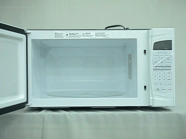
Click to zoom
Application Details
- Equipment Class
- 8CC - Part 18 Consumer Device
- Date of Grant
- Mar 10, 1999
- Application Purpose
- Original Equipment
- Date of Application
- Jan 25, 1999
- Equipment Note
- Microwave Oven
- Frequency Range
- 2400.00000000 - 2500.00000000
- Company
- LG Electronics USA, Inc.
- Country
- United States
Documents & Files
Document Text
Text extracted from the exhibit documents filed with the FCC. Open a document above to read the original.
Users Manual
. FCC ID : BEJS201XF .
Cover Letter(s)
FEDERAL COMMUNICATION COMMISSION Authorization and Standards BrenchRef. No.: L9901104 1919M St. North West Washington D.C. 20554-1300Date: Jan. 07, 1999 Subject: Application for certification on LG Electronics Microwave Oven FCC ID: BEJS201XF Model Nos.: MS-204Yd Magnetron: 2M246 (LG Electronics Inc., Korea) 2M248J (Toshiba Hokuto Electronics Corp., Japan) Gentleman: We, LG Electronics Inc., hereby submit this application letter to apply for FCC Certification for the subject new models. For your references, here is the following information. 1. The model MS-204YD is new model to be produced by LG Electronics Inc. 2. The model MS-204YD is to be installed on the counter-top and has touch control panel. 3. The model MS-204YD employs the turntable on the lower side of oven cavity for even cooking. 4. The above model is for household use. We have performed the relevant tests using the representative Model MS-204YD with LG Electronics Magnetron Type 2M246 and Toshiba Hokuto Electronics Magnetron type 2M248J at our laboratory as enclosed. No out-of-band frequency measurement and over-limit radiated emission was discovered. Your continued cooperation would be highly appreciated. Should you have any comments, please feel free to contact Mr. K. S. Kim at LG Electronics Chicago Office. Best Regards, B. H. Kim, Team Leader K. S. Kim, General Manager Cooking Appliance OBU,Engineering Department LG Electronics Inc.LG Electronics Chicago Office
External Photos
FRONT VIEW FCC ID : BEJS201XF CAVITY VIEW FCC ID : BEJS201XF
ID Label/Location Info
ID LABEL (1) FCC ID : BEJS201XF ID LABEL LOCATION (1) FCC ID : BEJS201XF ID LABEL (2) –Alternate FCC ID : BEJS201XF ID LABEL LOCATION (2) - ALTERNATE FCC ID : BEJS201XF
Internal Photos
WAVE GUIDE VIEW FCC ID : BEJS201XF UPPER VIEW WITHOUT ENCLOSURE FCC ID : BEJS201XF
Internal Photos
WAVE GUIDE VIEW FCC ID : BEJS201XF UPPER VIEW WITHOUT ENCLOSURE FCC ID : BEJS201XF
Internal Photos
PCB PART -1FCC ID ; BEJS201XF PCB PART -2FCC ID ; BEJS201XF
Schematics
SCHEMATIC DIAGRAM FCC ID : BEJS201XF
Test Report
LG Electronics Inc., EMI Laboratory 391-2 Gaeumjeong - Dong, Changwon City, Gyeongnam, Korea 641-711 REPORT of MEASUREMENT of ELECTROMAGNETIC INTERFERENCE TESTING Issued: January 4, 1999 1. Name of Applicant: LG Electronics Inc. 2. Address of Applicant: 6133 North River Road Suite, 1100 (Riverwary Plaza) Rosemont, IL 60018 3. Equipment Under Test: LG Electronics Inc., Microwave Oven Model MS-204YD with Magnetron Type 2M248J by Toshiba Hokuto Electronics Corp. 4. Power Supply: 120 V ac, 60 Hz 5. Test Requirements: CFR Title 47, Part 18 6. Test Procedure: OST MP-5 7. Instrument Used: Hioki Digital Power High Test Model 3181-01 Holaday Industries Inc. Microwave Survey Meter Model 1700 Electro Metrics Field Intensity Meter Model EMC-30 MKIV Electro Metrics Field Intensity Meter Model EMC-60 MKIV Electro Metrics Metering Module CRM-30 Hewlett Packard Frequency Counter 5350A Hewlett Packard Sweep Oscillator 8350B 8. Test Condition: The Equipment Under Test (EUT) was tested while operating at maximum RF output power. Loads of water in a glass beaker was used in amount specified by Test Procedure. 1/7 Model MS-204YD with Toshiba Magnetron FCC ID : BEJS201XF 9. Results of Testing: A. Input Power Input Power was measured using a Wattmeter. A 275 ml water load was placed in the center of the oven and the oven was operated at full output power for 6 minutes after which the reading was taken. A 275 ml water load was chosen for its compatibility with the UL procedure used by manufacturers to determine our input ratings. Voltage Current Input PowerManufacturer’s Rating 120 V ac, 60 Hz14. 5 A1643 W13.6 A B. RF Power Output The Calorimetric Method was used to determine maximum output power. A 1000 ml water load was placed in the center of the oven. A mercury thermometer was used to measure temperature rise. Quantity of WaterStarting Temperature Final TemperatureElapsed Time 1000 ml22.2 °C46.5 °C120 Sec (4.2 Joules/Cal) X (Volume in ml) X (Temperature Rise) Power (W) = Time in Seconds 4.2 x 1000 x 24.3 Power (W) = 120 Power (W) = 850.5 Watts 2/7 Model MS-204YD with Toshiba Magnetron FCC ID : BEJS201XF C. Frequency Measurements The fundamental operating frequency was measured with a substitution method using the Electro Metrics receiver, Hewlett Packard Sweep Oscillator and Frequency Counter. The receiver was turned to the maximum amplitude at the oven operating frequency. The Sweep Oscillator was substituted for operating the antenna and turned to the same frequency as the receiver. The frequency of the generator was determined using the frequency counter. The frequency was observed over a period of time, and with line voltage variation. The maximum frequency permitted in Part 18 is maximum 2.500 GHz and the minimum 2.400 GHz. No out-of-band frequency measurement was observed. Variation of Frequency With Time (1000 ml reduced to 200 ml) Maximum Frequency Observed: 2.472 GHz Minimum Frequency Observed: 2.455 GHz Variation of Frequency With Line Voltage (96 Volts to 150 Volts AC) Maximum Frequency Observed: 2.467 GHz Minimum Frequency Observed: 2.452 GHz D. Microwave Leakage Radiation leakage was measured in the as-received condition with the oven door closed using a microwave leakage meter. No power greater than 0.16 mW/ was observed at any location on the enclosure of the oven. A maximum of 1.0 mW/ is allowed in accordance with UL 923 standard. Hence, microwave leakage in the as-received condition with the oven door closed, did not exceed the specified limit. 3/7 Model MS-204YD with Toshiba Magnetron FCC ID : BEJS201XF E. Radiated Emissions Radiated emission was measured over a frequency range of 100 MHz to 10 GHz. For measurements the EUT was get set up in an Shielded Anechoic Chamber. The EUT was supported by a wood table, 1 m high in both cases, measurement above 1 GHz and below 1 GHz. The results of measurements above 1 GHz are shown on Data Page 1. Maximum readings were recorded after variations in antenna polarization, antenna height, EUT orientation, load location, and load volume. Readings were taken with the antenna 3 meters away from the EUT. Field intensity was then extrapolated to a 300 meters distance by multiplying by a factor of 0.01 as described in Section 2.2.6 of MP-5. No over-limit radiated emissions were discovered. The results of measurements below 1 GHz are found on Data Page 2 and 3. They represent horizontal and vertical antenna polarization at 3 meters respectively. 10. Test Engineer: Mr. S. G. Park Reviewed By: Mr. S. Y. Kim 4/7 Model MS-204YD with Toshiba Magnetron FCC ID : BEJS201XF Issued: Jan. 04, 1999 LABORATORY MEASUREMENTS ABOVE 1 GHz Data Page 1 Date Tested: Dec. 24, 1998 Equipment Under Test (EUT): Microwave Oven Model MS-204YD Mode of Operating (DUT): Maximum RF Power Test Requirements: CFR Title 47, Part 18 Test Equipment: Electro-Metrics FIM. EMC-60MKIV Antenna: Double Ridged Guide Antenna RGA-180 Detector Mode: Average Bandwidth: 1 MHz Measurement Distance: 3 meters FREQ. (GHz) Antenna Factor (dB) Cable Factor (dB) Load (ml) Load Locating Meter Reading (dBμV) Field Intensity @ 3 m dBμV/m Field Intensity @ 3 m (μV/m) Field Intensity @ 300 m (μV/m) FCC Limit @ 300 m (μV/m) 2.3929.40.6700Center23.753.4467.74.6832.6 2.5129.60.6700Center14.944.8173.81.7432.6 4.9034.40.9700Center23.958.4831.88.3232.6 4.9034.40.9700RF24.058.5841.48.4132.6 4.9034.40.9300Center23.157.6758.67.5932.6 4.9034.40.9300RF22.557.0707.97.0832.6 7.3536.81.2700Center16.253.1451.84.5232.6 7.3536.81.2700RF16.153.0446.74.4732.6 7.3536.81.2300Center14.351.2363.13.6332.6 7.3536.81.2300RF15.452.3412.14.1232.6 9.8038.01.3700Center6.2045.5188.41.8832.6 Note: RF = Right Front Corner 5/7 Model MS-204YD with Toshiba Magnetron FCC ID : BEJS201XF Issued: Jan. 04, 1998 LABORATORY MEASUREMENTS BELOW 1 GHz Data Page 2 Date Tested: Dec. 24, 1998 Manufacturer: LG Electronics Inc. Product Type: Household Microwave Oven Model No.: MS-204YD Mode of Operating: Maximum RF Power Test Requirements: CFR Title 47, Part 18 Test …
Text truncated - open the document above for the full version.
Test Report
LG Electronics Inc., EMI Laboratory 391-2 Gaeumjeong - Dong, Changwon City, Gyeongnam, Korea 641-711 REPORT of MEASUREMENT of ELECTROMAGNETIC INTERFERENCE TESTING Issued: January 4, 1999 1. Name of Applicant: LG Electronics Inc. 2. Address of Applicant: 6133 North River Road Suite, 1100 (Riverwary Plaza) Rosemont, IL 60018 3. Equipment Under Test: LG Electronics Inc., Microwave Oven Model MS-204YD with Magnetron Type 2M248J by Toshiba Hokuto Electronics Corp. 4. Power Supply: 120 V ac, 60 Hz 5. Test Requirements: CFR Title 47, Part 18 6. Test Procedure: OST MP-5 7. Instrument Used: Hioki Digital Power High Test Model 3181-01 Holaday Industries Inc. Microwave Survey Meter Model 1700 Electro Metrics Field Intensity Meter Model EMC-30 MKIV Electro Metrics Field Intensity Meter Model EMC-60 MKIV Electro Metrics Metering Module CRM-30 Hewlett Packard Frequency Counter 5350A Hewlett Packard Sweep Oscillator 8350B 8. Test Condition: The Equipment Under Test (EUT) was tested while operating at maximum RF output power. Loads of water in a glass beaker was used in amount specified by Test Procedure. 1/7 Model MS-204YD with Toshiba Magnetron FCC ID : BEJS201XF 9. Results of Testing: A. Input Power Input Power was measured using a Wattmeter. A 275 ml water load was placed in the center of the oven and the oven was operated at full output power for 6 minutes after which the reading was taken. A 275 ml water load was chosen for its compatibility with the UL procedure used by manufacturers to determine our input ratings. Voltage Current Input PowerManufacturer’s Rating 120 V ac, 60 Hz14. 5 A1643 W13.6 A B. RF Power Output The Calorimetric Method was used to determine maximum output power. A 1000 ml water load was placed in the center of the oven. A mercury thermometer was used to measure temperature rise. Quantity of WaterStarting Temperature Final TemperatureElapsed Time 1000 ml22.2 °C46.5 °C120 Sec (4.2 Joules/Cal) X (Volume in ml) X (Temperature Rise) Power (W) = Time in Seconds 4.2 x 1000 x 24.3 Power (W) = 120 Power (W) = 850.5 Watts 2/7 Model MS-204YD with Toshiba Magnetron FCC ID : BEJS201XF C. Frequency Measurements The fundamental operating frequency was measured with a substitution method using the Electro Metrics receiver, Hewlett Packard Sweep Oscillator and Frequency Counter. The receiver was turned to the maximum amplitude at the oven operating frequency. The Sweep Oscillator was substituted for operating the antenna and turned to the same frequency as the receiver. The frequency of the generator was determined using the frequency counter. The frequency was observed over a period of time, and with line voltage variation. The maximum frequency permitted in Part 18 is maximum 2.500 GHz and the minimum 2.400 GHz. No out-of-band frequency measurement was observed. Variation of Frequency With Time (1000 ml reduced to 200 ml) Maximum Frequency Observed: 2.472 GHz Minimum Frequency Observed: 2.455 GHz Variation of Frequency With Line Voltage (96 Volts to 150 Volts AC) Maximum Frequency Observed: 2.467 GHz Minimum Frequency Observed: 2.452 GHz D. Microwave Leakage Radiation leakage was measured in the as-received condition with the oven door closed using a microwave leakage meter. No power greater than 0.16 mW/ was observed at any location on the enclosure of the oven. A maximum of 1.0 mW/ is allowed in accordance with UL 923 standard. Hence, microwave leakage in the as-received condition with the oven door closed, did not exceed the specified limit. 3/7 Model MS-204YD with Toshiba Magnetron FCC ID : BEJS201XF E. Radiated Emissions Radiated emission was measured over a frequency range of 100 MHz to 10 GHz. For measurements the EUT was get set up in an Shielded Anechoic Chamber. The EUT was supported by a wood table, 1 m high in both cases, measurement above 1 GHz and below 1 GHz. The results of measurements above 1 GHz are shown on Data Page 1. Maximum readings were recorded after variations in antenna polarization, antenna height, EUT orientation, load location, and load volume. Readings were taken with the antenna 3 meters away from the EUT. Field intensity was then extrapolated to a 300 meters distance by multiplying by a factor of 0.01 as described in Section 2.2.6 of MP-5. No over-limit radiated emissions were discovered. The results of measurements below 1 GHz are found on Data Page 2 and 3. They represent horizontal and vertical antenna polarization at 3 meters respectively. 10. 10. Test Engineer: Mr. S. G. Park Reviewed By: Mr. S. Y. Kim 4/7 Model MS-204YD with Toshiba Magnetron FCC ID : BEJS201XF Issued: Jan. 04, 1999 LABORATORY MEASUREMENTS ABOVE 1 GHz Data Page 1 Date Tested: Dec. 24, 1998 Equipment Under Test (EUT): Microwave Oven Model MS-204YD Mode of Operating (DUT): Maximum RF Power Test Requirements: CFR Title 47, Part 18 Test Equipment: Electro-Metrics FIM. EMC-60MKIV Antenna: Double Ridged Guide Antenna RGA-180 Detector Mode: Average Bandwidth: 1 MHz Measurement Distance: 3 meters FREQ. (GHz) Antenna Factor (dB) Cable Factor (dB) Load (ml) Load Locating Meter Reading (dBμV) Field Intensity @ 3 m dBμV/m Field Intensity @ 3 m (μV/m) Field Intensity @ 300 m (μV/m) FCC Limit @ 300 m (μV/m) 2.3929.40.6700Center23.753.4467.74.6832.6 2.5129.60.6700Center14.944.8173.81.7432.6 4.9034.40.9700Center23.958.4831.88.3232.6 4.9034.40.9700RF24.058.5841.48.4132.6 4.9034.40.9300Center23.157.6758.67.5932.6 4.9034.40.9300RF22.557.0707.97.0832.6 7.3536.81.2700Center16.253.1451.84.5232.6 7.3536.81.2700RF16.153.0446.74.4732.6 7.3536.81.2300Center14.351.2363.13.6332.6 7.3536.81.2300RF15.452.3412.14.1232.6 9.8038.01.3700Center6.2045.5188.41.8832.6 Note: RF = Right Front Corner 5/7 Model MS-204YD with Toshiba Magnetron FCC ID : BEJS201XF Issued: Jan. 04, 1998 LABORATORY MEASUREMENTS BELOW 1 GHz Data Page 2 Date Tested: Dec. 24, 1998 Manufacturer: LG Electronics Inc. Product Type: Household Microwave Oven Model No.: MS-204YD Mode of Operating: Maximum RF Power Test Requirements: CFR Title 47, Part 18 Tes…
Text truncated - open the document above for the full version.
Contact Information
Applicant
David Kim(Team leader, LGEUS NA Policy & Regulatory Affairs)
Technical Contact
LG Electronics, Inc.Kyeom Soon Kim
[email protected]847-692-4500
6133 N. River Road, Suite 1100 · Rosemont, Illinois · United States
Non-Technical Contact
LG Electronics, Inc.Kyeom Soon Kim
[email protected]847-692-4500
Technical Specifications
| # | Rule Parts | Frequency Range | Power Output |
|---|---|---|---|
| 1 | 18 | 2.40 GHz - 2.50 GHz | 1150 W |
Other Applications from LG Electronics USA, Inc.

BEJTFHOBINI1F1
Jan 08, 2025Telematics
Equipment Class
DTS - Digital Transmission SystemBEJNT-16Z90TS
Oct 02, 2024Notebook Computer
Equipment Class
DSS - Part 15 Spread Spectrum TransmitterBEJSP-PEW8
Sep 26, 2024Stylus Pen
Equipment Class
DCD - Part 15 Low Power Transmitter Below 1705 kHzBEJ-RSMV2
Sep 24, 2024RF Module
Equipment Class
FDS - Part 15 Field Disturbance SensorBEJTFBMEIBN3EU
Sep 24, 2024Telematics
Equipment Class
NII - Unlicensed National Information Infrastructure TX