BEJW1642STLCD Monitor
LG Electronics USA, Inc.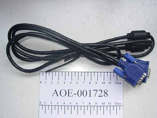
Click to zoom
Application Details
- Equipment Class
- JBP - Part 15 Class B Computing Device Peripheral
- Date of Grant
- Jan 24, 2008
- Application Purpose
- Original Equipment
- Date of Application
- Jan 17, 2008
- Equipment Note
- LCD Monitor
- Company
- LG Electronics USA, Inc.
- Country
- United States
Documents & Files
Document Text
Text extracted from the exhibit documents filed with the FCC. Open a document above to read the original.
Users Manual
Make sure to read the Important Precautionsbefore using the product. Keep the User's Guide(CD) in an accessible place for future reference. See the label attached on the product and give the information to your dealer when you ask for service. W1642S User’s Guide A1 This unit has been engineered and manufactured to ensure your personal safety, however improper use may result in potential electrical shock or fire hazards. In order to allow the proper operation of all safeguards incorporated in this display, observe the following basic rules for its installation, use, and servicing. On Safety Use only the power cord supplied with the unit. In case you use another power cord, make sure that it is certified by the applicable national standards if not being provided by the supplier. If the power cable is faulty in any way, please contact the manufacturer or the nearest authorized repair service provider for a replacement. The power supply cord is used as the main disconnection device. Ensure that the socket-outlet is easily accessible after installation. Operate the display only from a power source indicated in the specifications of this manual or listed on the display. If you are not sure what type of power supply you have in your home, consult with your dealer. Overloaded AC outlets and extension cords are dangerous. So are frayed power cords and broken plugs. They may result in a shock or fire hazard. Call your service technician for replacement. Do not Open the Display. There are no user serviceable components inside. There are Dangerous High Voltages inside, even when the power is OFF. Contact your dealer if the display is not operating properly. To Avoid Personal Injury : Do not place the display on a sloping shelf unless properly secured. Use only a stand recommended by the manufacturer. Do not drop an object on or apply impact to the product. Do not throw any toys or objects on the product screen. It can cause injury to human, problem to product and damage the display. To Prevent Fire or Hazards: Always turn the display OFF if you leave the room for more than a short period of time. Never leave the display ON when leaving the house. Keep children from dropping or pushing objects into the display's cabinet openings. Some internal parts carry hazardous voltages. Do not add accessories that have not been designed for this display. When the display is to be left unattended for an extended period of time, unplug it from the wall outlet. In the presence of thunder and lightning, never touch the power cord and signal cable because it can be very dangerous. It can cause electric shock. Important Precautions A2 Important Precautions On Installation Do not allow anything to rest upon or roll over the power cord, and do not place the display where the power cord is subject to damage. Do not use this display near water such as near a bathtub, washbowl, kitchen sink, laundry tub, in a wet basement, or near a swimming pool. Displays are provided with ventilation openings in the cabinet to allow the release of heat generated during operation. If these openings are blocked, built-up heat can cause failures which may result in a fire hazard. Therefore, NEVER: Block the bottom ventilation slots by placing the display on a bed, sofa, rug, etc. Place the display in a built-in enclosure unless proper ventilation is provided. Cover the openings with cloth or other material. Place the display near or over a radiator or heat source. Main power breaker is the power cord and this breaking device must be located at a location where it is easy to operate. Do not rub or strike the Active Matrix LCD with anything hard as this may scratch, mar, or damage the Active Matrix LCD permanently. Do not press the LCD screen with your finger for a long time as this may cause some afterimages. Some dot defects may appear as Red, Green or Blue spots on the screen. However, this will have no impact or effect on the display performance. If possible, use the recommended resolution to obtain the best image quality for your LCD display. If used under any mode except the recommended resolution, some scaled or processed images may appear on the screen. However, this is characteristic of the fixed-resolution LCD panel. On Cleaning Unplug the display before cleaning the face of the display screen. Use a slightly damp (not wet) cloth. Do not use an aerosol directly on the display screen because over-spraying may cause electrical shock. On Repacking Do not throw away the carton and packing materials. They make an ideal container in which to transport the unit. When shipping the unit to another location, repack it in its original material. On Disposal The fluorescent lamp used in this product contains a small amount of mercury. Do not dispose of this product with general household waste. Disposal of this product must be carried out in accordance to the regulations of your local authority. Important Precautions NOTE THE MANUFACTURER IS NOT RESPONSIBLE FOR ANY RADIO OR TV INTRERFERENCE CAUSED BY UNAUTHORIZED MODIFICATIONS TO THIS EQUIPMENT.SUCH MODIFICATIONS COULD VOID THE USER'S AUTHORITY NOTE This epuipment has been tested and found to comply with the limits for a class B digital device,pursuant to part 15 of the FCC Rules.These limits are designed to provide reasonable protection against harmful interference in a residential installation.This equipment generates,uses and can radiate radio frequency cause harmful interference to radio communications.However,there is no guarantee that interference will not occur in a particular installation.If this which can be determined by turning the equipment off and on,the user is encouraged to try to correct the interference by one or more of the following measures: -Reorient or relocate the receiving antenna. -Increase the separation between the equipment and the receiver. -Connect the equipment into an outlet on a circuit different from that to which the receiver is connected. energy and,if not in…
Text truncated - open the document above for the full version.
Block Diagram
Block diagram L V D S L V D S L V D S Analog I(R/G/B) D-Sub LIPS Filter 5V 18V 5V Regulator Regulator 3.3V Vcc5V 3.3V KEY 1.8V 1.8V Module SDA/SCL EEPROM (System) EEPROM (System) 3.3V 1360x768@60Hz Dual Interface Engine Display Processing Engine Response Time Enhancement LVDS Panel Interface OSD Clock Generator MCU DRAM TSUMU16AWL Flash ROM Flash ROM 3.3V Crystal Crystal 14.318MHz Crystal : TXC CORPORATION;HUA LIAN XING (alternate) Regulation : 14.31818MHZ 30PPM 20pF INPUT: 120V 60Hz FUNDAMENTAL OPERATION FR EQUENCY IS 0.030-0.083 MHz . 18V 18V Inverter(4Lamps) DESCRIPTION OF BLOCK DIAGRAM 1. Video Controller Part.This part amplifies the level of video signal for the digital conversion and converts from the analog video signalto the digital video signal using a pixel clock.The pixel clock for each mode is generated by the PLL.The range of the pixel clock is 1 0 5MHz In W1642S. This part consists of the Scaler, ADC converter, TMDS receiver and LVDS transmitter.The Scaler gets the video signal converted analog to digital, interpolates input to 1360*738 resolution signal and outputs 8-bit R, G, B signal to transmitter.2. Power Part.This part consists of the one 3.3V, and one 1.8V regulators to convert power which is provided 5V in Power board.185V is provided for inverter in W1642S. Also, 5V is converted 3.3V and 1.8V by regulator. Converted power is provided for IC in the main board.The inverter converts from DC 18V to AC 700Vrms and operates back-light lamps of module in W1642S. 3. MICOM Part.This part is include video controller part. And this part consists of EEPROM IC , control data, Reset IC and the Micom.The Micom distinguishes polarity and frequency of the H/V sync are supplied from signal cable.The controlled data of each modes is stored in EEPROM. Power Board Block Diagram EMI COMPONENTS LINE 100 ~ 240V INPUT RECTIFIER AND FILTER ENERGY TRANSFER OUTPUT RECTIFIER AND FILTER 18V 5V GND SIGNAL COLLENT- ION PHOTO- COUPLER ISOLATION PWM CONTROL CIRCUIT HVDC 67KHz PRIMARY SECONDARY 50 ~ 60Hz LIPS BLOCK DIAGRAM
External Photos
FIGURE 1 LCD MONITOR (M/N: W1642ST) G ENERAL APPEARANCE (FRONT VIEW) F IGURE 2 LCD MONITOR (M/N: W1642ST) G ENERAL APPEARANCE (BACK VIEW) FIGURE 3 LCD MONITOR (M/N: W1642ST) P ORTS F IGURE 4 LCD MONITOR (M/N: W1642ST) D-S UB CABLE
ID Label/Location Info
Label Location Information Refer to the below red arrow: (For example)
Internal Photos
FIGURE 1 LCD MONITOR (M/N: W1642ST) C OVER REMOVED F IGURE 2 LCD MONITOR (M/N: W1642ST) BOARDS REMOVED FIGURE 3 LCD MONITOR (M/N: W1642ST) B UTTON BOARD (COMPONENT SIDE) F IGURE 4 LCD MONITOR (M/N: W1642ST) B UTTON BOARD (SOLDERED SIDE) FIGURE 5 LCD MONITOR (M/N: W1642ST) P OWER BOARD (COMPONENT SIDE) F IGURE 6 LCD MONITOR (M/N: W1642ST) P OWER BOARD (SOLDERED SIDE) FIGURE 7 LCD MONITOR (M/N: W1642ST) M AIN BOARD (COMPONENT SIDE) F IGURE 8 LCD MONITOR (M/N: W1642ST) M AIN BOARD (SOLDERED SIDE) FIGURE 9 LCD MONITOR (M/N: W1642ST) C HIP ON MAIN BOARD F IGURE 10 LCD MONITOR (M/N: W1642ST) C RYSTAL ON MAIN BOARD FIGURE 11 LCD MONITOR (M/N: W1642ST) LCD P ANEL LABEL 1 F IGURE 12 LCD MONITOR (M/N: W1642ST) LCD P ANEL LABEL 2 FIGURE 13 LCD MONITOR (M/N: W1642ST) LCD P ANEL MAIN BOARD (FRONT VIEW) F IGURE 14 LCD MONITOR (M/N: W1642ST) LCD P ANEL MAIN BOARD (BACK VIEW) FIGURE 15 LCD MONITOR (M/N: W1642ST) LCD P ANEL MAIN BOARD LABEL F IGURE 16 LCD MONITOR (M/N: W1642ST) D EBUG 1 FIGURE 17 LCD MONITOR (M/N: W1642ST) D EBUG 2 F IGURE 18 LCD MONITOR (M/N: W1642ST) DEBUG 3
Operational Description
LG Electronics U.S.A., Inc. FCC ID: BEJW1642ST 1 Equipment Description The Equipment Under Test (EUT) is the LG Electronics U.S.A., Inc. LCD Monitor, W1642ST. General Specification Function Type M156B1- L01 Display 15.6 inches (39.62cm) Flat Panel Active matrix-TFT LCD Anti-Glare coating 15.6 inches viewable Pixel pitch 0.252*0.252mm Max. resolution VESA 1360*768@60Hz Recommend. resolution VESA 1360*768@60Hz Horizontal Freq. 28 - 83 kHz (Automatic) Vertical Freq. 56 - 75 Hz (Automatic) LCD Panel Input Form Separate TTL, Positive/Negative SOG (Sync On Green) Signal Input 15 pin D-Sub Connector Option Video Input Input Form RGB Analog (0.7 Vp-p/75 ohm) Power Input AC 100-240V~ 50/60Hz 0.8A Power Consumption On Mode:18W(Typ.) Sleep Mode≤1 W Off Mode≤1 W Plug & Play DDC 2AB Operating Conditions Temperature10 ̊C to 35 ̊C Humidity10 % to 80 % non-CondensingEnvironmental Conditions Storage Conditions Temperature-20 ̊C to 60 ̊C Humidity5 % to 90 % non-Condensing With Stand Width:38.17 cm / 15.03 inches Height:32.30 cm / 12.72 inches Depth:19.84 cm / 7.81 inches Dimensions& Weight Without Stand Width: 38.17 cm / 15.03 inches Height: 26.03 cm / 10.25 inches Depth:5.67 cm / 2.23 inches Stand Base Attached ( ), Detached ( O ) Others Power cord Wall-outlet type or PC-outlet type LG Electronics U.S.A., Inc. FCC ID: BEJW1642ST 2 EUT Operating Conditions a. Setup the EUT and Peripherals as shown in the report Sec. 3.2. b. Turn on the power of all equipment and the EUT. c. Set the contrast & brightness of EUT to maximum. d. PC system ran the self-test program “EMC Test” by windows XP and set “H” characters to EUT through graphic card, the EUT’s screen displayed and filled with “H” pattern by it’s resolution. (Via D-Sub Input). e. Repeat above procedure from c to d for difference test mode (VGA 640*480@60Hz/ VGA 1024*768@60Hz/ VGA 1360*768@60Hz). f. The other peripherals devices were driven and operated during the test.
Test Report
Prepared For : LG Electronics U.S.A., Inc. 1000 Sylvan Avenue, Englewood Cliffs, NJ 07632, United States Prepared By : Audix Technology (Shanghai) Co., Ltd. 3F 34Bldg 680 Guiping Rd, Caohejing Hi-Tech Park, Shanghai, China 200233 Tel: +86-21-64955500 Fax: +86-21-64955491 Report No. : ACI-F08001 Date of Test : Dec 26-28, 2007 Date of Report : Jan 02, 2008 Application for FCC Certificate On Behalf of LG Electronics U.S.A., Inc. LCD Monitor Model No.: W1642ST Serial No.: E07122401 FCC ID : BEJW1642ST TABLE OF CONTENTS Page 1 SUMMARY OF STANDARDS AND RESULTS .......................................................................... 4 1.1 Description of Standards and Results......................................................................................... 4 2 GENERAL INFORMATION.......................................................................................................... 5 2.1 Description of Equipment Under Test........................................................................................5 2.2 Peripherals .................................................................................................................................. 6 2.3 Description of Test Facility ........................................................................................................ 7 2.4 Measurement Uncertainty .......................................................................................................... 7 3 CONDUCTED EMISSION TEST .................................................................................................. 8 3.1 Test Equipment........................................................................................................................... 8 3.2 Block Diagram of Test Setup ..................................................................................................... 8 3.3 Conducted Emission Limit [FCC Part 15 Subpart B 15.107(a)]................................................ 9 3.4 Test Configuration...................................................................................................................... 9 3.5 Operating Condition of EUT .................................................................................................... 10 3.6 Test Procedures ........................................................................................................................ 11 3.7 Test Results .............................................................................................................................. 11 4 RADIATED EMISSION TEST..................................................................................................... 15 4.1 Test Equipment......................................................................................................................... 15 4.2 Block Diagram of Test Setup ................................................................................................... 15 4.3 Radiated Emission Limit [FCC Part 15 Subpart B 15.109(a)]................................................. 16 4.4 Test Configuration.................................................................................................................... 16 4.5 Operating Condition of EUT .................................................................................................... 17 4.6 Test Procedures ........................................................................................................................ 17 4.7 Test Results .............................................................................................................................. 18 5 DEVIATION TO TEST SPECIFICATIONS .............................................................................. 22 6 DEBUG DESCRIPTION ...............................................................................................................23 TEST REPORT FOR FCC CERTIFICATE Applicant : LG Electronics U.S.A., Inc. Manufacturer : LG Electronics Nanjing Display Co., Ltd. EUT Description : LCD Monitor (A) Model No. : W1642ST (B) Serial No. : E07122401 (C) Power Supply : 120V/60Hz Test Procedure Used: FCC RULES AND REGULATIONS PART 15 SUBPART B CLASS B 2007.09 AND ANSI C63.4-2003 The device described above is tested by Audix Technology (Shanghai) Co., Ltd. to determine the maximum emission levels emanating from the device. The maximum emission levels are compared to the FCC Part 15 Subpart B (Class B) and ICES-003, Issue 4 February 2004 (CISPR 22:2002) limits both radiated and conducted emissions. The test results are contained in this test report and Audix Technology (Shanghai) Co., Ltd. is assumed full responsibility for the accuracy and completeness of these measurements. This report shows that the EUT (M/N: W1642ST; S/N: E07122401) which was tested in 3m anechoic chamber on Dec 26-28, 2007 is technically compliance with the FCC official limits also. This report applies to above tested sample only. This report shall not be reproduced in part without written approval of Audix Technology (Shanghai) Co., Ltd. This report contains data that are not covered by the NVLAP accreditation. This report must not be used by the client to claim product certification, approval, or endorsement by NVLAP, NIST, or any agency of the federal government. Date of Test : Dec 26-28, 2007 Prepared By: ALAN HE / Assistant Reviewer: SAMMY CHEN / Deputy Assistant Manager Approved Signatory: IAN CHIEN / Assistant Manager 1 SUMMARY OF STANDARDS AND RESULTS 1.1 Description of Standards and Results The EUT have been tested according to the applicable standards as referenced below: Description / Test Item Test Standard Results Meets Limit EMISSION Conducted Disturbance At main terminal FCC RULES AND REGULATIONS PART 15 SUBPART B 2007.09 AND ANSI C63.4-2003 Pass 15.107(a) Class B Radiated Disturbance FCC RULES AND REGULATIONS PART 15 SUBPART B 2007.09 AND ANSI C63.4-2003 Pass 15.109(a) Class B 2 GENERAL INFORMATION 2.1 Description of Equipment Under Tes…
Text truncated - open the document above for the full version.
Test Setup Photos
Test Set-Up Photos 1. Conducted Emission Test F RONT VIEW S IDE VIEW 2. Radiated Electromagnetic Emission Test FRONT VIEW OF RADIATED EMISSION TEST B ACK VIEW OF RADIATED EMISSION TEST S ETUP WITH MAXIMUM DETECTED EMISSION AT HORIZONTAL POLARIZATION (VGA 1024*768@60HZ) S ETUP WITH MAXIMUM DETECTED EMISSION AT VERTICAL POLARIZATION (VGA 1024*768@60HZ)
Contact Information
Applicant
David Kim(Team leader, LGEUS NA Policy & Regulatory Affairs)
Technical Contact
Audix Technology (Shanghai) Co., Ltd.Byron Kwo
[email protected]+86-21-64955500
3F 34Bldg 680 Guiping Rd., Caohejing Hi-Tech Park · Shanghai · China
Non-Technical Contact
Audix Technology (Shanghai) Co., Ltd.Byron Kwo
[email protected]+86-21-64955500
Test Firm
Audix Technology ( Shanghai ) Co., Ltd.Byron Kwo
Technical Specifications
| # | Rule Parts | Frequency Range | Power Output |
|---|---|---|---|
| 1 | 15B | - | - |
Other Applications from LG Electronics USA, Inc.

BEJTFHOBINI1F1
Jan 08, 2025Telematics
Equipment Class
DTS - Digital Transmission SystemBEJNT-16Z90TS
Oct 02, 2024Notebook Computer
Equipment Class
DSS - Part 15 Spread Spectrum TransmitterBEJSP-PEW8
Sep 26, 2024Stylus Pen
Equipment Class
DCD - Part 15 Low Power Transmitter Below 1705 kHzBEJ-RSMV2
Sep 24, 2024RF Module
Equipment Class
FDS - Part 15 Field Disturbance SensorBEJTFBMEIBN3EU
Sep 24, 2024Telematics
Equipment Class
NII - Unlicensed National Information Infrastructure TX