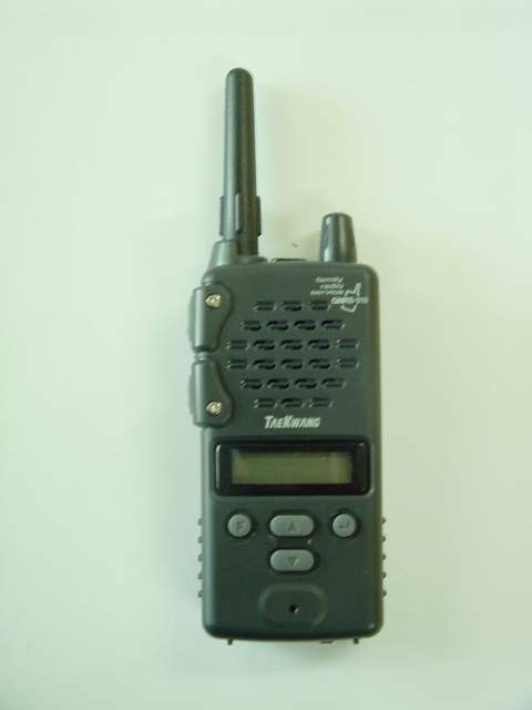
BESGMRS310FRS/GMRS Combination Transceiver
Tae Kwang Industrial Co Ltd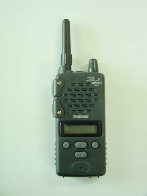
Click to zoom
Application Details
- Equipment Class
- FRF - Part 95 Family Radio Face Held Transmitter
- Date of Grant
- Aug 05, 2002
- Application Purpose
- Original Equipment
- Date of Application
- Jun 25, 2002
- Equipment Note
- FRS/GMRS Combination Transceiver
- Frequency Range
- 467.55000000 - 467.72500000
- Company
- Tae Kwang Industrial Co Ltd
- Country
- South Korea
Documents & Files
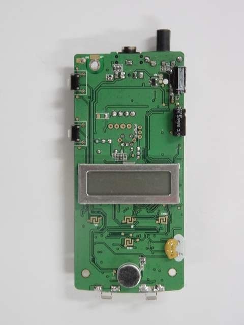

Document Text
Text extracted from the exhibit documents filed with the FCC. Open a document above to read the original.
Users Manual
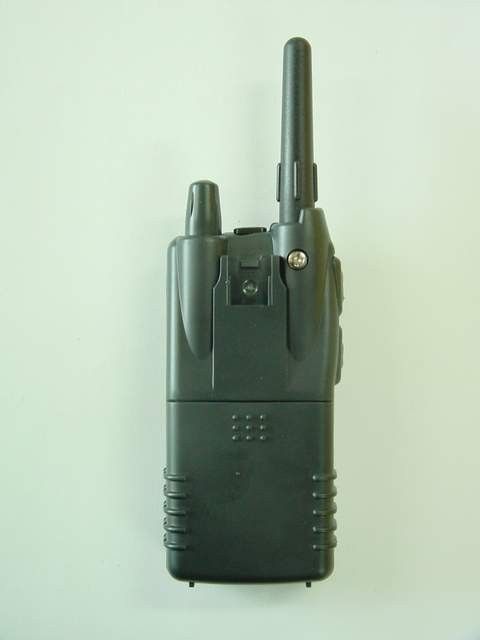
- 1 - USER’S GUIDE. ( GMRS-310 ) Table of Contents 1. Introduction. 2. Contents of Package. 3. Safety Infomation. 4. To Install Batteries . 5. To Attatch Belt Clip. 6. Controls and Functions 7. Basis use method 8. Before think that is breakdown 9. Standard Before use 1 . Introduction. The GMRS-310 is a lightweight, palm-sized radio that you can carry almost anywhere. Use this radio at shopping malls, amusement parks, or sports events to keep in touch with family and friends. Communicating with radio require no service fee or license, and can be used anywhere as listed by the FCC. Your radio and other radios must be on same channel and CTCSS(Continuous Tone Controlled Squelch System) to communicate. The channel is the radio frequency wave your radio uses to transmit. The CTCSS code filters out static, noise, and unwanted chatter on the same radio channel. The GMRS-310 operates on Family Radio Service (FRS) frequencies from 462.5625MHz to 449.2625MHz. Refer to the Channel Frequency and Code Charts beginning on page 7 to 10 for channel and CTCSS code choice. The GMRS-310 is easy to use. But take a few minutes to read this user’s guide so that you can use all features of the GMRS-310. Please read this guide carefully to use all features of GMRS-310 before use. 2 . Contents of Package. FRS & GMRS Unit belt clip Ear set Hand-Strap User’s guide 3 . Safety Infomation. - 2 - When using the rechargeable batteries, use the radio after it is fully charged. ( The GMRS-310 charger is designed for the supplied Ni-MH battery. But the Ni-CD rechargeable battery also can be charged using the charger.) CAUTION: Never charge alkaline batteries. It can damage the radio seriously. Handle the radio gently. Avoid shaking or shocking the radio. And keep the radio in safety. Do not expose the radio to long periods of direct sunlight, nor place the radio close to Heating appliances. Avoid extremes in exposure to water, heat, and cold. It may cause a serious trouble. Do not hold the antenna when the radio is in use . Holding the antenna affects the effective range. 4 . To Install Batteries . NOTE: The GMRS-310 requires 4 AAA batteries. Radio must be OFF before removing batteries. - 3 - - After removing the belt clip, open the battery compartment cover. 1. Pushing back side the battery compartment cover 2. Lift the compartment cover off. 3. Insert 4 AAA batteries. Match the battery polarities with those marked in the battery compartment. 4. Slide the battery compartment cover forward until it snaps into place. 5 . To Attach Belt Clip. 1) Align the belt clip to the mounting rails on the back of the radio. 2) Slide the belt clip downward until it locks into place. 3) To remove Belt Clip Pull the belt clip upward while lifting the lever on the top. - When separate belt clip in substance : Scram in state that lift Clip upper part furtively.(picture) 6. Controls and Functions 1) GMRS-310
Users Manual
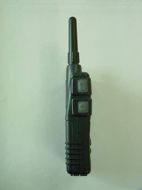
- 4 - Speaker. LCD Window. ENTER Key : Input function that select using "F" button and / button. Reception air state sends CALL signal. / (UP/DOWN) Keys : Use to set the function options. Microphone. FUNCTION Key. : Use to select a desired function menu. PTT(Push To Talk) Key : Press and hold to talk on the radio. Press twice to transmit a call tone. MONITOR/SCAN button : Been using channel monitor or search channel . On-Off/Volume Knob : Turns the radio on/off. Adjusts the volume when the radio is on. Antenna. External Microphone/Charger Jack : Plug the microphone or charger into this jack. 2) LCD Display. - 5 - CALL : Appears when is sending CALL signal to other person. VOX : Appears when the VOX is activated. SCAN : Appears while channel scan is functioning. BEEP : Appears when the BEEP function is on. LOCK : Appears when the key Lock function is activated. Battery : Mark battery state by 3 steps. PRIV : Appear when established ton code. (01 ~ 38). Displays the current ton code. (01 ~ 38) "00" is situation that ton code is not set. TX : Appears while transmitting by pressing and holding the [PTT] key. BUSY : Appears while monitoring or receiving. You must not transmit while this icon is visible. Display the current channel number. (1 ~ 22) 7. Basis use method 1 . Power On/Off and VOLUME adjustment 1) Power On Until lamp enters [VOL/PWR] handle to LCD, it is dolly for clockwise. 2) Power Off Do so that sign may disappear to LCD to turn [VOL/PWR] handle for class clockwise.
Users Manual
- 6 - 3) VOLUME adjustment When power supply is lighted, decrease if volume increases and turns for class clockwise if operate [VOL/PWR] handle for clockwise . 2 . Currency function . ? [PTT] (Push To Talk) button utilization 1) Status that do not click any button is automatic reception air status. 2) If click side [PTT] button, get into transmitter state. When click [PTT] button, transmit message to other person. This time, "TX" icon appears to LCD. 3) If message delivery ends, put [PTT] button. Come into in reception air state. 3 . SCAN/MONITOR function 1) SCAN function a. If click side [MON] shortly, search use frequency. b. While search channel, if click [ ]/[ ] channel search direction increase of each channel or Convert for decreasing direction. c. Finish While search channel, receive signal until reception ends in relevant channel if there is reception lake, and reception two, [after 5 seconds] automatically from next time channel search begin d. If click side [MON] again shortly, stop channel search and return before channel search to channel. 2) MONITOR function . a. If click side [MON] long, regardless of ton code, signal that enter to established channel plain number. b. If there is no aural signal to established channel, background noise is heard. Reception indication icon “BUSY” of LCD appears. 4 . LAMP/LOCK function 1) LAMP function If press [F]/[ ]/[ ], LCD is lighted for 5 seconds. 2) LOCK function . - Button fastening function . a . Can prevent case that change If click [F] long, get into button fastening state and "Key indication" icon of LCD appears channel or tone code to a mistake. b . If press [F] again long, LCD is "Key indication" icon this getting into button fastening cancellation state. 5.CALL function . If press [ENTER] in reception stand-by status, CALL signal is sent out to other person. 6 . Channel selection & ton code (CTCSS) selection . 1) Channel selection(1~22) a. [F] 1st repeatedly channel selection mode select . b. Set -channel using [ ]/[ ] while channel blinks. c. [ENTER] repeatedly established channel store . 2) Ton code (CTCSS) selection (01~38) a. [F] 2nd repeatedly ton code mode select . b. Establish Channel using [ ]/[ ] while Tone Code blinks. (If select '00', can receive signal regardless of other person's ton code.) c. [ENTER] stores establishment repeatedly. 3) channel & frequency spectrum designation Specified frequency and channel are marked alternately in LCD when press [F] and [ENTER] at the same time. 7 . DUAL WATCH function By function that can receive channel separately except existent established channel the two channels alternately reception signal inspect . 1) [F] 3rd repeatedly DUAL WATCH mode select . - 7 - 2) “DCH OFF” is blinker to LCD. 3) Select channel that want using [ ]/[ ]. 4) [ENTER] stores establishment repeatedly. 5) When cancel, press side [MON] shortly. 8 . Transmission of a message output HI/LOW establishment function . 1)[F] 4th repeatedly transmission of a message output HI/LOW establishment mode select . 2)“TPr HI” is blinker to LCD. 3) After use [ ]/[ ] and do so that do “TPr Lo”, press [ENTER]. Transmission of a message output is stored by LOW mode. RF output can become 0.5 W and spare battery in LOW mode. It is useful function if use in near distance. off 8CH ~ 14CH LOW mode fixing channel be . 9 . CALL sound establishment function 1) [F] 5th repeatedly CALL sound establishment mode select . 2) “CAL 1” is blinker to LCD. 3) Using [ ]/[ ] CALL sound [CAL 0] ~ [CAL 5] select . 4) [ENTER] stores establishment repeatedly. 10 . BEE sound (sound that ring when press button) establishment(ON)/cancellation(OFF) function . 1) [F] 6th repeatedly BEEP sound establishment(ON)/cancellation(OFF) mode select . 2) “BP ON” is blinker to LCD. 3) Choose set/revocation using [ ]/[ ]. 4) [ENTER] stores establishment repeatedly. 11 . Roger Beep establishment(ON)/cancellation(OFF) function After send a letter [PTT] repeatedly by signal that inform transmission of a message end, can hear short melody when remove [PTT] hand . Can enter if Beep sound is established, and can not enter if Beep sound is defrosted. 1) [F] 7th repeatedly Roger Beep establishment mode select . 2) “Rb ON” is blinker to LCD. 3) Select establishment (ON)/cancellation (OFF) using [ ]/[ ]. 4) [ENTER] stores establishment repeatedly. 12 . VOX establishment (ON)/cancellation (OFF) VOX(Voice activated transmission) is function that talk without pressing [PTT]. If sound does not enter to MIC, get into reception stand-by status automatically. If turn on while put out power supply, VOX becomes cancellation (OFF). 1) [F] 8th repeatedly VOX establishment/cancellation establishment mode select . 2) “VOX OFF” is blinker to LCD. 3) After use [ ]/[ ] and do so that do “VOX ON”, press [ENTER]. 4) Enter by VOX mode “VOX 3” is blinker. Using [ ]/[ ] VOX sensitivity after select [SEN 1]~[SAN 10], [ENTER] press . (Is sensitive number is low. ) 5) “DLY 150” is blinker during VOX continuance time. [dLY 025] ~ after select [dLY 400] Press [ENTER]. (VOX continuance time can select in "0.25 ~ 4 seconds" by TX (transmission of a message) preservation time.) 13 . Outside speaker/microphone connection function . If 3.5 ø terminals that can connect outside speaker or Mike be, and connect, interior speaker is intercepted. 14 . Charge function . - Can use using sold charger separately. 8. Before think that is breakdown - 8 - - Desire Before ask repair, to inquire to A/S center in case of is not solved after inspect following item. Symptoms upper Point sword four clauses Power supply is not lighted. 1. Confirm whether battery is discharged. 2. Confirm whether new battery and old battery mix. 3. Confirm whether battery polarity is threaded wrongly. Tone is not said. 1 . Confirm whether volume is established by smallest Tone is not clean. 1. Confirm whether battery is discharged. 2. Is not very far away with other person? BEEP sound is not said. 1 . Confirm whether is by BEEP sound OFF (cancel…
Text truncated - open the document above for the full version.
ID Label/Location Info
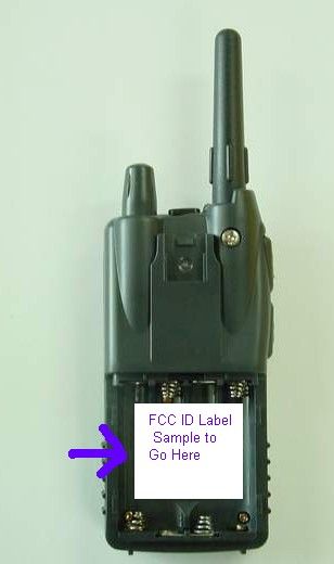
FCC MARKING / LABEL FOR PART 15 FCC ID: BESGMRS310 BRAND NAME: TRUTALK MODEL NO.: GMRS-310 THIS DEVICE COMPLIES WITH PART 15 OF THE FCC RULES. OPERATION IS SUBJECT TO THE FOLLOWING TWO CONDITIONS: (1) THIS DEVICE MAY NOT CAUSE HARMFUL INTERFERENCE, AND (2) THIS DEVICE MUST ACCEPT AND INTERFERENCE RECEIVED, INCLUDING INTERFERENCE THAT MAY CAUSE UNDESIRED OPERATION.
Operational Description
GMRS-310 02-01-28 Page 1 1. THEORY OF OPERATIONS 1-1. Circuit Composition and Operation Theory The basic explanation for the circuit composition GMRS-310 consists mainly of the one board controlling the analog circuit parts and the digital circuit parts for the other control. 1-2. Receiver GMRS-310 transmission parts is composed in the double conversion system, which has the 1 st IF frequency of double 21.7 MHz and the 2 nd IF frequency of 450 KHz. With the RF fronted which has an excellent band characteristics and skirt characteristics, the 2 pole MCF used in the 1 st IF, and the 3 pole ceramic filter in the 2 nd IF, the reception interrupting factors such as the image and the sensitivity repression are reduced for the more stable reception. 1-2-1. RF Front-end The signal received by the antenna will be transmitted to the band pass filter through the antenna switching circuit consisted of L607, D601, D602. The front RF amplifier transistor Q101 consists of the C101, C102, C103, C105 input band pass filter and SAW101 output band pass filter, primarily diminishes the other signal rather than the 1 st IF image and other signal within the reception band and amplifier only the necessary signal within the RF 1-2-2. 1 st Mixer The receiver which has been amplifier in the RF front-end is provided to the base of the 1 st mixer Q102. The 1 st L/O signal provide from the VCO is supplied to the emitter of Q102 and Converted to the 1 st IF 21.7 MHz 1-2-3. 1 st IF Filter and 1 st IF Amplifier The signal covered by Q102 to 21.7 MHz, the 1 st frequency, change its impedance through C114, L105 and then is infused to the fundamental MCF which has the center frequency of 21.7 MHz and the width of +/- 3.75 KHz. Here, the signal reduces the image and other unwanted signal for the 2 nd IF , and changes its impedance again through the R124. Then the signal is infused to the Q103, the 1 st IF amplifier. The signal infused to the Q103 is amplifier approximately by 20 dB in other to acquire the required reception sensitivity, and infused to the IC101 which functions as the 2 nd mixer, the 2 nd IF amplifier, and the FM detector. 1-2-4. 2 nd Mixer, and IF, FM Detector (IC101) The receiver IF signal of 21.7 MHz, which has been infused to IC101 is mixed with the 2 nd L/O converted to 450 KHz, the 2 nd IF frequency. The receiver signal converted to the 2 nd IF signal frequency passed through the CF101, the ceramic filter of 450 KHz again. After the limiting inside the IC101 and the FM demodulating by the quadrature detector inside the IC101, the signal offers the output through the 9 th pin of IC101. The squelch circuit is composed to detect the noises from the received signal demodulate in the 9 th pin of the IC101. For this purpose, the noise filter is using the OP amplifier inside the IC101. GMRS-310 02-01-28 Page 2 1-2-6. De-Emphasis and 300Hz HPF (U801 ) The audio signal which has been FM demodulate in the IC101 is supplies to the IC401C, IC402D which function as the De- emphasis and 300Hz HPF. Since the IC401C has the 300Hz HPF with the 1st characteristics and the De-emphasis characteristics with the corner frequency of approximately 200Hz, and IC402D has the 300Hz HPF with the 4th characteristics, they function as a normal De-emphasis and also reduce the signal such as CTCSS to unwanted noises from the speaker. 1-2-6. Audio Power Amplifier (IC201) The receiver audio signal, which has been adjusted to the appropriate volume by IC201 supplied to the 2 nd pin of the IC201 and amplified approximately by 20 dB. Then, it turns up the speaker with the maximum output of 0.5 watts. The 6 th pin of IC201 is the audio mute terminal. If a voltage supply to the 6 th pin of the IC201 is not supplied to this terminal, the IC201 stops functioning as the audio power amplifier regardless of the signal supplied to the 2 nd pin of the IC201, and there is no sound emitter from the speaker. 1-3. Transmitter The transmitter parts of the GMRS-310 is designed to amplify the RF signal oscillated and modulated by the synthesizer to approximately 2.0W by the power transistor of Q603. 1-3-1. Pre-emphasis ( IC401D ) The voice signal input from the microphone is pre-emphasized at the IC401D. The signal which comes out of the IC401D is limited to a certain amplitude for the voice signal not to exceed the allowable band width assigned for transmission. 1-3-2. KHz LPF ( IC401A,B ) After passing the IC401D limiter, the signal is combined with the CTCSS tone at the digital circuits, and is supplied to the 3KHz LPF has the 4th characteristics and adjusts the assigned frequency band width not to exceed the allowable range. 1-3-3. Tx Power (Q603) The transmitted signal of approximately 0dBm , combined at the at the VCO buffer amplifier Q302 is supplied to the drain of the Q603 amplifiers, through pre-amplifier(Q601) and driver amplifier(Q602) . The transmitted signal amplifier to 2.0W here passes the TX LPF of the 2 nd characteristics of the L605 and the C607, C608 and RX/TX switching takes place by the D601. After this, the signal is provided to the antenna the TX LPF of the 1 st characteristics consisted of the C612, C613, C614, C615, C616, C617, C618, L608, L609, L611. 1-4. “GMRS” Frequency Synthesizer 1-4-1. Voltage Control Oscillator (VCO) The VCO of oscillates 462.5625 MHz to 462.7250 MHz under the transmission condition and 440.8625 MHz to 441.025 MHz under the reception condition. The VCO consist of the clip oscillator of the Q301 and contains the oscillator frequency of approximately 21.7 MHz during the transmission/reception GMRS-310 02-01-28 Page 3 conversion. That is since the VCO should oscillate relatively low frequency during reception compared to transmission, the D302 is biased by the Q303. Therefore as a result, the C323 is added in parallel to the resonance circuit of the VCO to oscillate a low frequency. During transmission, a relatively high frequency should be oscillate compared to reception. Therefore, the D302 is adversely b…
Text truncated - open the document above for the full version.
Parts List/Tune Up Info
GMRS-310 02-01-28 Page 5 2. ALIGNMENT INSTRUCTIONS WARNING Any repairs or adjustment should be made under the supervision of a qualified radio-telephone technician. 2-1. VCO 2-1-1. Power Supply Voltage The power supply voltage should be set for 6.0 Vdc. 2-1-1. VCO Adjustment A. Connect high impedance voltmeter between R302 and C311 B. Adjust L302 for 1.0V. 2-2. TRANSMITTER 2-2-1. Power Supply Voltage The power supply voltage should be set for 6.0 V DC measured at the radio during transmit. Periodically check the supply voltage during the alignment procedure. 2-2-2. Frequency Setting A. Connect a frequency counter or Communications Service Monitor to the antenna connector through an RF power attenuates (5 watt minimum rating, 20 dB minimum attenuation). B. Depress the PTT switch. C. Adjust the TCXO such that output frequency is equal to the channel. Frequency with a maximum error of ±300 Hz. D. Adjust CT301 for ±300 Hz. E. Release the PTT switch. 2-2-3. Output Power Alignment A. Set the power supply voltage for 6.0 V DC. B. Connect a communications Service Monitor or a wattmeter and dummy load to the antenna connector. C. Depress the PTT switch. D. To be convinced for 2.0 watt output power with a maximum error of ± 0.2 watt. E. Release the PTT switch. 2-2-4. Deviation Adjustment A. Connect an audio generator to the microphone jack JIG. The audio frequency should be set at 1 KHz B. Connect an FM deviation meter or communication Service Monitor to the antenna connector Through an RF power attenuates (5 watt minimum rating, 20 dB minimum attenuates ). Set the monitor to read peak deviation. C. Depress the PTT switch. D. Adjust the audio generator level 100 mV rms. E. Adjust RV721 for 2.3 KHz maximum deviation. F. Release the PTT switch. GMRS-310 02-01-28 Page 6 2-3. RECEIVER Note : Insure that the proper channel has been selected before proceedings with the alignment procedure. 2-3-1. Power Supply Voltage. The proper voltage for testing is 6.0 V DC. 2-3-2. 12dB SINAD Alignment A. Connect an RF signal generator or Communications Service Monitor to the antenna connect. B. Connect a SINAD meter and oscilloscope across the speaker terminals. C. Set the output level of the RF signal generator for –47 dBm the generator should be set for 1.5 KHz deviation of a 1 KHz tone. D. Set the audio output level for 0.6 Vrms by adjusting volume. E. Reduce the output level of the RF signal generator for produce a 12 dB SINAD indication. 2-3-3. Squelch Alignment A. Connect an RF signal generator or Communications Service Monitor to the antenna connect. B. Connect a SINAD meter and oscilloscope across the speaker terminals. C. Set the output level of the RF signal generator for –125 dBm the generator should be set for 1.5 KHz deviation of a 1 KHz tone. D. Set the audio output level for 0.6 Vrms by adjusting volume. E. Adjust RV101 for audio output disappears. GMRS-310 02-01-28 Page 7 3. SEMICONDUCTOR AND FUNCTION 3-1. Transistor -------------------------------------------------------------------------------------------------------------------------------------------- Ref No. Description Manufacturer Function -------------------------------------------------------------------------------------------------------------------------------------------- Q101 2SC4226 NEC RX RF Amplifier Q102 2SC4226 NEC RX Mixer Q103 KTC3880 KEC RC IF Amplifier Q201 KRC104S KEC AF Mute Control Q202 KTA1504S KEC AF Mute Control Q301 2SC4226 NEC VCO OSC Q302 2SC4226 NEC VCO Buffer Amplifier Q303 KRC104S KEC TX VCO Switching Q421 KTC3875S KEC Tone Detector Q601 2SC4226 NEC TX RF Amplifier Q602 2SC4226 NEC TX Driver Amplifier Q603 NE5510279A NEC TX Power Amplifier Q604 KRC104S KEC Power Hi/Low Control Q701 2SC4226 NEC VOX Amplifierl Q704 KRC104S KEC Mic Mute Q802 KRC104S KEC AF Path Q901 KRA105S KEC RX B+ Control Q902 KRA105S KEC TX B+ Control Q903 KRA105S KEC VCO B+ Control Q907 KRC111S KEC Back Light LED Control 3-2. Integrated Circuit -------------------------------------------------------------------------------------------------------------------------------------------- Ref No. Description Manufacturer Function -------------------------------------------------------------------------------------------------------------------------------------------- IC101 DBL5018 Daewoo 2 nd IF Mixer/AF Detector IC301 TB31202FN Toshiba PLL IC IC801 HD6438024 Hitachi CPU IC201 LM386 National AF Amplifier IC901 R1120N331B RICOH 3.3V Regulator IC802 24C02 Samsung EEPROM IC401C,402A DBL324 Daewoo RX HPF IC402B,C,D DBL324 Daewoo RX Tone LPF(Tone Detector) IC401A,B,D DBL324 Daewoo TX BPF
Test Report
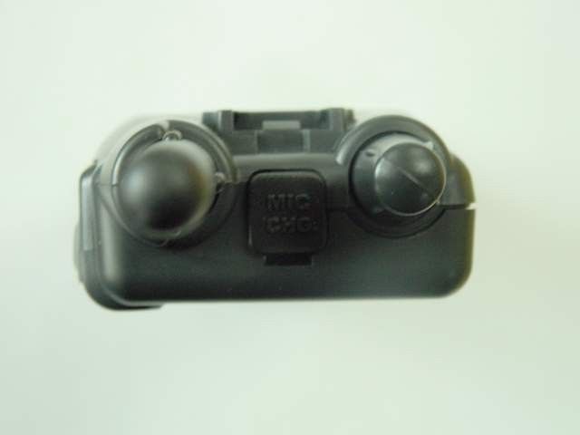
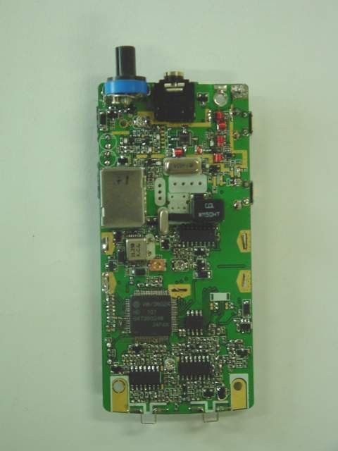
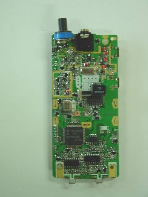
APPLICANT: TAEKWANG INDUSTRIAL CO., LTD. FCC ID: BESGMRS310 REPORT #: T\TIC\507KT2\507KT2TestReport.doc TABLE OF CONTENTS TABLE OF CONTENTS LIST APPLICANT: TAEKWANG INDUSTRIAL CO., LTD. FCC ID: BESGMRS310 TEST REPORT: PAGE 1......COVER SHEET - GENERAL INFORMATION & TECHNICAL DESCR. PAGE 2......TECHNICAL DESCRIPTION CONTINUED PAGE 3......RF POWER OUTPUT PAGE 4......MODULATION CHARACTERISTICS PAGE 5......AUDIO FREQUENCY RESPONSE GRAPH PAGE 6......MODULATION LIMITING GRAPH – 300Hz PAGE 7......MODULATON LIMITING GRAPH – 1000Hz PAGE 8......MODULATION LIMITING GRAPH – 3000Hz PAGE 9......AUDIO LOW PASS FILTER GRAPH PAGE 10.....OCCUPIED BANDWIDTH PAGE 11.....OCCUPIED BANDWIDTH PLOT PAGE 12.....OCCUPIED BANDWIDTH PLOT - CW PAGE 13.....SPURIOUS EMISSIONS AT ANTENNA TERMINALS PAGE 14.....UNWANTED RADIATION - GMRS PAGE 15.....UNWANTED RADIATION - FRS PAGE 16.....METHOD OF MEASURING RADIATED SPURIOUS EMISSIONS PAGE 17.....FREQUENCY STABILITY PAGE 18-21..LIST OF TEST EQUIPMENT EXHIBITS CONTAINING: EXHIBIT 1.........FCC ID LABEL SAMPLE EXHIBIT 2.........SKETCH OF LABEL LOCATION EXHIBIT 3.........EXTERNAL PHOTO – FRONT VIEW EXHIBIT 4.........EXTERNAL PHOTO – TOP VIEW EXHIBIT 5.........EXTERNAL PHOTO – SIDE VIEW EXHIBIT 6.........EXTERNAL PHOTO – REAR VIEW EXHIBIT 7.........INTERNAL PHOTO – COMPONENT VIEW EXHIBIT 8.........INTERNAL PHOTO – COMPONENT VIEW WITHOUT SHIELD EXHIBIT 9.........INTERNAL PHOTO – COPPER VIEW EXHIBIT 10........BLOCK DIAGRAM EXHIBIT 11........SCHEMATIC EXHIBIT 12........USER'S MANUAL EXHIBIT 13........CIRCUIT DESCRIPTION EXHIBIT 14........TUNING PROCEDURE EXHIBIT 15........TEST SET UP PHOTO APPLICANT: TAEKWANG INDUSTRIAL CO., LTD. FCC ID: BESGMRS310 REPORT #: T\TIC\507KT2\507KT2TestReport.doc Page 1 of 21 GENERAL INFORMATION REQUIRED FOR CERTIFICATION 2.1033(c)(1)(2) TAEKWANG INDUSTRIAL CO., LTD. will manufacture the FCCID: BESGMRS310 GMRS/FRS COMBINATION TRANSCEIVER in quantity, for use under FCC RULES PART 95. TAEKWANG INDUSTRIAL CO., LTD. #191-1, ANYANG-7 DONG ANYANG, GYONGGI-DO, KOREA 2.1033 (c) TECHNICAL DESCRIPTION 2.1033(c)(3) Instruction book. A draft copy of the instruction manual is included as EXHIBIT 12 2.1033(c) (4) Type of Emission: 10K8F3E 95.631 Bn = 2M + 2DK M = 3000 D = 2.4K Bn = 2(3000)+2(2.4) = 10K8F3E GMRS Authorized Bandwidth 20.0 kHz 2.1033(c)(5) GMRS Frequency Range: 1. 462.5500 13. 462.7000 95.621 2. 462.5625 14. 462.7125 3. 462.5750 15. 462.7250 4. 462.5875 16. 467.5500 5. 462.6000 17. 467.5750 6. 462.6125 18. 467.6000 7. 462.6250 19. 467.6250 8. 462.6375 20. 467.6500 9. 462.6500 21. 467.6750 10. 462.6625 22. 467.7000 11. 462.6750 23. 467.7250 12. 462.6875 2.10311c)(6)(7) The Maximum Output Power Rating: GMRS – HIGH .5 WATTS LOW .2 WATTS FRS - .1 Watts FRS Authorized Bandwidth 12.5kHz 2.1033(c)(5) FRS Frequency Range: 1. 462.5625 8. 467.5625 95.627 2. 462.5875 9. 467.5875 3. 462.6125 10. 467.6125 4. 462.6375 11. 467.6375 5. 462.6625 12. 467.6625 6. 462.6875 13. 467.6875 7. 462.7125 14. 467.7125 MHz APPLICANT: TAEKWANG INDUSTRIAL CO., LTD. FCC ID: BESGMRS310 REPORT #: T\TIC\507KT2\507KT2TestReport.doc Page 2 of 21 2.1033(c)(6)(7) Power Output shall not exceed 0.50 Watts effective 95.639 radiated power. There can be no provisions for 95.649 increasing the power or varying the power. 2.1033(c)(8) DC Voltages and Current into Final Amplifier: FINAL AMPLIFIER ONLY FOR LOW POWER SETTING INPUT POWER: (6.0V)(.210A) = 1.26 Watts FOR HIGH POWER SETTING INPUT POWER: (6.0V)(.600A) =3.60 Watts 2.1033(c)(9) Tune-up procedure. The tune-up procedure is included as EXHIBIT 14. 2.1033(c)(10) Complete Circuit Diagrams: The circuit diagram is included as EXHIBIT 11 of this report. The block diagrams are included as EXHIBIT 10 of this report. 2.1033(c)(11) A photograph or a drawing of the equipment identification label is included as exhibit No. 1. 2.1033(c)(12) Photographs(8"X10") of the equipment of sufficient clarity to reveal equipment construction and layout, including meters, labels for controls, including any view under shields. See exhibits 3-9. 2.1033(c)(13) Digital modulation is not allowed. 2.1033(c)(14) The data required by 2.1046 through 2.1057 is submitted below. APPLICANT: TAEKWANG INDUSTRIAL CO., LTD. FCC ID: BESGMRS310 REPORT #: T\TIC\507KT2\507KT2TestReport.doc Page 3 of 21 95.639 Power Output shall not exceed 50.0 Watts effective radiated power. There can be no provisions for 95.649 increasing the power or varying the power. 2.1046(a) RF power is measured by the substitution method as outlined in TIA/EIA - 603. With a nominal battery voltage of 6.0 V, and the transmitter properly adjusted the RF output measures: OUTPUT POWER: GMRS: HIGH .5 Watts ERP LOW .2 Watts ERP FRS: .1 Watts ERP 2.1046(a) RF power output. The test procedure used was TIA/EIA-603 S2 APPLICANT: TAEKWANG INDUSTRIAL CO., LTD. FCC ID: BESGMRS310 REPORT #: T\TIC\507KT2\507KT2TestReport.doc Page 4 of 21 2.1047(a)(b) Modulation characteristics: AUDIO FREQUENCY RESPONSE The audio frequency response was measured in ac- cordance with TIA/EIA Specification 603. The audio frequency response curve is shown on the next page. The audio signal was fed into a dummy microphone circuit and into the microphone connector. The input required to produce 30 percent modulation level was measured. See Page 5 of report. 2.1047(b) Audio input versus modulation The audio input level needed for a particular per- percentage of modulation was measured in accor- dance with TIA/EIA Specification 603. The audio input curves versus modulation are on the following pages. Curves are provided for audio input frequen- cies of 300, 1000, and 3000 Hz. See Pages 6,7 & 8 of report. 95.637 Post Limiter Filter Each GMRS transmitter, except a mobile station transmitter with a power of 2.5Watts or less, must be equipped with an audio low pass filter. At any frequency between 3 & 20 kHz the filter must have an attenuation of 60log (f/3) greater than the attenuation at 1kHz. See Page 9 of report. APPLICANT: TAEKWANG INDUSTRIAL CO., LTD. F…
Text truncated - open the document above for the full version.
Contact Information
Applicant
Shi Tae Kim(Chief Engineer)
0343 443 3654-3655Fax: 0343 467 87726
Technical Contact
Timco Engineering, Inc.Mario R de Aranzeta
[email protected]888-472-2424
849 N.W. State Road 45 · Newberry, Florida · United States
Non-Technical Contact
Timco Engineering, Inc.Sharon A Hoffman
[email protected]888-472-2424
Test Firm
Timco Engineering, Inc.S Sanders
Technical Specifications
| # | Rule Parts | Frequency Range | Power Output | Emission | Tolerance |
|---|---|---|---|---|---|
| 4 | 95A | 467.55 MHz - 467.725 MHz | 200.00 mW | 10K8F3E | 5 ppm |
Other Applications from Tae Kwang Industrial Co Ltd

BESTKP-910A
May 15, 2000900 MHz CORDLESS TELEPHONE
Equipment Class
DXX - Part 15 Low Power Communication Device Transmitter
BESFRS-1200
Mar 29, 1999FAMILY RADIO TRANSCEIVER
Equipment Class
FRF - Part 95 Family Radio Face Held Transmitter
BESFRS-1600
Mar 28, 1999FRF - Part 95 Family Radio Face Held Transmitter
Equipment Class
FRF - Part 95 Family Radio Face Held TransmitterBES9EHWLT
Sep 04, 1985DXT - Part 15 Low Power Transceiver, Rx Verified
Equipment Class
DXT - Part 15 Low Power Transceiver, Rx VerifiedBES9EHST-350
Feb 03, 1985DXX - Part 15 Low Power Communication Device Transmitter
Equipment Class
DXX - Part 15 Low Power Communication Device Transmitter