BGA-XMXP03XM Radio RX and FM TX
Audiovox Corporation
Click to zoom
Application Details
- Equipment Class
- DXX - Part 15 Low Power Communication Device Transmitter
- Date of Grant
- Aug 24, 2006
- Application Purpose
- Original Equipment
- Date of Application
- Aug 23, 2006
- Equipment Note
- XM Radio RX and FM TX
- Frequency Range
- 88.10000000 - 107.90000000
- Company
- Audiovox Corporation
- Country
- United States
Documents & Files
Document Text
Text extracted from the exhibit documents filed with the FCC. Open a document above to read the original.
Users Manual
2 Table of Contents Congratulations.......................................................................... 3 FCC Information........................................................................ 4 Cautions and Warnings ............................................................. 5 Contents XMC10 ........................................................................ 6 Accessory Kit .......................................................................... 7 Installation/Wiring Precautions.................................................. 8 Setting Up and Installing Your Kit .............................................. 9 Cabling Interconnections ........................................................ 9 Installing the Cradle Mount Base Assembly .......................... 9 Interconnect Diagram.......................................................... 10 Using Other Manufacturer’s Mounts .................................... 15 Installing the Xpress XM ® Into the Cradle ............................ 15 Connection Options............................................................. 17 Installation Guidelines......................................................... 20 Warranty................................................................................... 24 3 Congratulations Thank you for purchasing the Audiovox Xpress XM ® Satellite Car Kit. You are one step closer to experiencing the latest innovation in XM ® Satellite Radio. XM ® Satellite Radio will revolutionize your vehicle or in-home entertainment. XM ® features over 170 digital channels — the most commercial-free music, over 30 channels of news, sports, talk and entertainment, over 20 dedicated channels of XM ® Instant Traffic & Weather, and the deepest play-list in the industry with access to over 2 million titles! XM ® Satellite Radio service gives you the power to choose what you want to hear - wherever and whenever you want it. XM ® is America’s #1 Satellite Radio provider with over 4 million customers. Your Audiovox Xpress XM ® receiver must be used with an accessory kit, such as the Audiovox Home Kit, Boom Box or Vehicle Kit as required by your specific installation needs. These kits are available at retailers where Audiovox main units are sold. Required subscription for service sold separately. Installation costs and other fees and taxes may apply, including a one-time activation fee. All fees and programming subject to change. College sports games subject to availability. Subscriptions subject to Customer Agreement included with the XM Welcome Kit and available at www.xmradio.com. Only available in the 48 contiguous United States. ©2005 XM ® Satellite Radio Inc. XM ® is a trademark of XM ® Satellite Radio. All rights reserved. All other trademarks are the property of their respective owners. 4 FCC Information NOTE:This equipment has been tested and found to comply with the limits for a Class B digital device, pursuant to Part 15 of the FCC Rules. These limits are designed to provide reasonable protection against harmful interference in a residential installation. This equipment generates, uses and can radiate radio frequency energy and, if not installed and used in accordance with the instructions, may cause harmful interference to radio communications. However, there is no guarantee that interference will not occur in a particular installation. If this equipment does cause harmful interference to radio or television reception, which can be determined by turning the equipment off and on, the user is encouraged to try to correct the interference by one or more of the following measures: — Reorient or relocate the receiving antenna. — Increase the separation between the equipment and receiver. — Connect the equipment into an outlet on a circuit different from that to which the receiver is connected. — Consult the dealer or an experienced radio/TV technician for help. This device complies with Part 15 of the FCC Rules. Operation is subject to the following two conditions: (1) This device may not cause harmful interference, and (2) this device must accept any interference received, including interference that may cause undesired operation. The user is cautioned that changes or modifications not expressly approved by XM ® Satellite Radio, Inc. can void the user’s authority to operate this device. Please note that the power cable supplied with your XMC10 Car Cradle has permently attached ferrite beads. It is the responsibility of the user to use the power cable with these ferrite beads. By adhering to these warnings and safety considerations, stated in the manual and by XM®, accidents. 5 Cautions and Warnings 1. Do not install the XMC10 car cradle in a position that hinders your view through the windshield, or obstructs viewing of the dashboardindicators and displays. 2. Do not install the unit where it may obstruct the operation or deployment of safety devices, such as airbags, etc. 3. Do not allow operation of the unit to detract from safe driving practices; remember that you are responsible as the vehicle operator to adhere to all safe driving and traffic regulations. 4. By adhering to these warnings and safety considerations,serious accidents and/or personal injury can be avoided. 6 Swivel Bracket 1 pc. Contents XMC10 12 Volt-to-5 Volt DC Power Adapter 1 pc. Install Manual Antenna 1 pc. Cradle XMC10 1 pc. 7 ACCESSORY KIT Alcohol Cleaning Pad, Surface Cleaning Pad, Instruction Sheet, Antenna Cable Exit Plug CLA Female Socket 1 pc. OPTIONAL Audio Cable (P/N SAT-RCA) FM Direct Adapter (P/N XMFM-1) Contents XMC10 (Cont) Cassette Adapter 1pc. 8 Installation/Wiring Precautions 1.To prevent a short-circuit, be sure to turn off the ignition and remove the negative (-) battery cable prior to installation. Connect power wires last. 2.Do not install the unit in the locations exposed to direct sunlight or, in areas subject to extreme temperatures. 3.Incorrect installation may cause damage to the system. Mount the unit firmly in …
Text truncated - open the document above for the full version.
Users Manual
Installing the FM Coupler in your vehicle Please note that the CLA cable supplied with your device includes permanently attached ferrite beads at each end. It is the responsibility of the user to use the cable with the ferrite beads.The user is cautioned that changes or modifications not expressly approved by XM Satellite Radio, Inc. can void the user’s authority to operate this device. This device complies with Part 15 of the FCC Rules. Operation is subject to the following two conditions: (1) This device may not cause harmful interference, and (2) this device must accept any interference received, including interference that may cause undesired operation.This equipment has been tested and found to comply with the limits for a Class B digital device, pursuant to Part 15 of the FCC Rules. These limits are designed to provide reasonable protection against harmful interference in a residential installation.This equipment generates, uses and can radiate radio frequency energy and, if not installed and used in accordance with the instructions, may cause harmful interference to radio communications. However, there is no guarantee that interference will not occur in a particular installation. If this equipment does cause harmful interference to radio or television reception, which can be determined by turning the equipment off and on, the user is encouraged to try to correct the interference by one or more of the following measures:- Reorient or relocate the receiving antenna.- Increase the separation between the equipment and receiver.- Connect the equipment into an outlet on a circuit different from that to which the receiver is connected.- Consult the dealer or an experienced radio/TV technician for help. FCC INFORMATION: 2 3 FCC Information Contents Installation Locations 5 Installing the FM Coupler Overview 4 External FM Whip Antenna Routing 8 Internal On Glass Antenna Routing 12 Installation Setup 6 Installing the FM Coupler Overview Installation Locations To install the FM Coupler, first find a suitable location that works in your vehicle. You need to determine the location of your vehicle’s FM Antenna and properly routing the FM Coupler cables to your FM antenna..For best audio performance, install the FM Coupler by either clipping it directly to an external whip antenna (locations 1 through 4) or against an interior on-glass antenna using the additional window Contact Bracket (locations 5 through 7). Step by step installation instructions are provide later in this docu-ment. Your vehicle’s FM antenna will be located in one of seven common locations: 1. front fender 2. rear fender 3. roof top front 4. roof top rear 5. adhered on edges of windshield 6. adhered on top of rear window 7. adhered on rear side glass (in some SUVs) 1 3 5 4 6 2 7 4 5 Install your XM Radio and vehicle kit as described in your XM Radio User’s Manual but leave the XM antenna disconnected from the dock. 1. Locate your vehicles FM antenna and determine the best routing method to get the FM Coupler output cable to the FM antenna. (For external whip antennas, the Coupling Clip needs to be routed outside of the vehicle. For internal on glass antennas, all routing is inside the passenger compartment and the Contact Bracket is used. 2. Connect the FM Coupler input cable to the vehicle dock antenna input. 3. The following steps will guide you through the installation of your FM Coupler 4. Connect the XM Antenna to the FM Coupler antenna input, located on the coupler module about 2 feet from the end of the input cable. Tuck away any excess input cable and the coupler module behind dash or other hidden location for a clean installation. 5. Route the output cable with Coupling Clip to your vehicle FM antenna. ( This guide assumes you have already installed your XM antenna per the instructions in your XM radio user guide. The position of the XM antenna in the illustration below is for example only. There is no need to change your XM antenna installation.) Note: When routing the FM Coupler cable use pre-existing wire channels whenever possible to avoid loose wires on the interior of the vehicle which are susceptible to damage and to maintain a professional looking installation. Route cable carefully by taking notice of how doors open and close, as well as how seats move when they are adjusted so you can be certain there is ample clearance provided for the cable. Avoid inadvertent damage that may be caused by kinking, crimping, twisting or chafing the cables. Secure and tie wrap the excess cable under your dash board, between the seat and the console, or on the floor under a seat or floor mat. Securing the excess cable will help to prevent it from interfering with the everyday use of your vehicle, improve the appearance of the installa-tion, and avoid any undesirable accidental damage to the cables that might result in loss of satellite signal or FM Coupler performance. without boot glass contactbracket inside your vehicle outside car dock XM car antenna coupling clip coupling module input cableoutput cable external antenna External Antenna Internal on-glass antenna boot power XM antenna Installation Setup Installation Setup 6 7 XM car antenna XM receiver coupler clip coupler module XM car antenna XM receiver coupler clip coupler module 8 9 External FM Whip Antenna Routing External FM Whip Antenna Routing For a whip antenna in the rear, route the output cable along the floor under the door jam trim or under the carpet to the rear of the passenger compartment as shown in the illustration below. Route the cable into the trunk through available wire channels and out of the trunk to the external whip antenna. Always cross the weather seal at the lowest part of the trunk to reduce water leaks. For a whip antenna in the front, route the output cable under the dash or carpet to the door jam and outside as shown in the illustration. Route the cable across the weather seal near the bottom of the door to reduce water leaks. After routin…
Text truncated - open the document above for the full version.
Cover Letter(s)
Subject: RE: Review of FM Modulator Date: Tue, 22 Aug 2006 18:51:40 -0400 X-MS-Has-Attach: X-MS-TNEF-Correlator: Thread-Topic: Review of FM Modulator, Audiovox FCC ID: BGA-XMXP03 Thread-Index: AcbFdYAozy4+OeztQFSGGOXGIiJ6sAAcZxv/ABU864A= From: "Rashmi Doshi" <[email protected]> To: <[email protected]>, "Joe Dichoso" <[email protected]>, "Raymond Laforge" <[email protected]> X-OriginalArrivalTime: 22 Aug 2006 22:51:41.0141 (UTC) FILETIME=[88768050:01C6C63D] X-NAS-BWL: Found match for '[email protected]' on the allowed list (417 addresses, 0 domains) X-NAS-Classification: 0 X-NAS-MessageID: 1104 X-NAS-Validation: {9C3ED9BD-B7B8-4535-997B-0205512A69A2} Tim: I just wanted to update you on our latest decision. We have decided that in order to process the application, we are going to require that the applicant submit data showing compliance with two configurations. - Show compliance with tabletop tests using a whip antenna over a ground plane when the coupler is connected to the whip antenna. - Show compliance in 3 different vehicles with windshield antennas when the coupler is placed on the windshield close to the antenna traces. The vehicle should be representative of different configurations of windshield antennas (rear, side) and large or small cars. Once you have reviewed the test reports for completeness and have determined the filing is complete, please contact us to unblock the specific grantee code. At this time please do not process any more applications than what we agree with. Thus we expect one with XXXX grantee code and two with XXXX in the next couple of days. Once the grants are issued we will block the codes again. Please contact Ray LaForge to unblock the grantee code. On Friday, you may have to contact Joe Dichoso. Let me know if you have any additional questions. I appreciate your help in coordinating this with us. Thanks, Rashmi Doshi Page 1 of 12Rashmi Doshi, 06:51 PM 8/22/2006 -0400, RE: Review of FM Modulator 8/22/2006Printed for "Timothy R. Johnson" <[email protected]>
External Photos
Co nn e c t s to XM Ra d i o Clips onto car’s aria l antenna C o nnects to XM RF Antenna RF FM Ferrite overmold Spring clip Close up of clip coupler
External Photos
Connects to XM RF Antenna Co nn e c t s to XM Ra d i o C o nnects to Car Radio C o nnects to Car antenna Direct FM Coupler
External Photos
Front Face Back Face Top Bottom Right Side Left Side Externa l Anten n a co n necte d thr o ug h car cr a d le External Antenna and FM Coupl er connected through car crad le
ID Label/Location Info
Location of FCC Label
Internal Photos
Cas e O pen wit h PCB I n s i de Cas e O pen wit h PCBs Rem o ved Front of PCB Back of PCB
Test Report
Test Results No. R-11574-2 Page 3 of 54 Retlif Testing Laboratories R Test Program Summary Test Results Number: R-11574-2 Customer: XM Radio P.O. Number: 115178-0-IECH Test Sample: XM Radio Receiver containing an 88 to 108 MHz Low Power Transmitter Brandname: Xpress Model Number: 136-4335 Serial Number: 051101005213640400 FCC ID Number: BGA-XMXP03 Test Specification: • FCC Rules and Regulations, Part 15, Subpart C, Paragraph 15.239 (a)(b)(c). • FCC Rules and Regulations, Part 15, Subpart B, Paragraph 15.107 (a) and 15.109 (a). • FCC Rules and Regulations, Part 15, Subpart A, Paragraph 15.31 (d). • ANSI C63.4-2003 (American National Standard for Methods of Measurement of Radio- Noise Emissions from Low Voltage Electrical and Electronic Equipment in the Range of 9 kHz to 40 GHz). Modes of Operation: • During FCC Part 15 Subpart C, Paragraph 15.239 (b)(c) radiated emissions tests; the EUT was configured to transmit a continuous Frequency Modulated (FM) frequency with normal modulation at 88.1, 96.9 and 107.9 MHz onto a representative FM aerial antenna. • During FCC Part 15 Subpart C, Paragraph 15.239 (b)(c) radiated emissions tests; the EUT was configured to transmit a continuous Frequency Modulated (FM) frequency with normal modulation at 88.1, 96.9 and 107.9 MHz into an XM antenna. • During FCC Part 15 Subpart C, Paragraph 15.239 (a) bandwidth tests, the EUT was configured to transmit a continuous Frequency Modulated (FM) frequency with normal modulation at 88.1, 96.9 and 107.9 MHz and without modulation. • During FCC Part 15 Subpart B, Paragraph 15.107(a) conducted emissions tests and 15.109(a) radiated emissions tests; the EUT was configured to receive an XM satellite radio signal then send the audio out to support stereo speakers. Notes: All Radiated and Conducted Emissions test data contained within this test report was acquired by Florida Atlantic University. Retlif was contracted only to complete the test report and files associated with the filing for certification. Inquiries regarding test data should be directed to Florida Atlantic University. Test Results No. R-11574-2 Page 4 of 54 Retlif Testing Laboratories R Test Methods: The following table depicts the test methods that were performed on the XM Radio Receiver and the corresponding test results: FCC Paragraph Test Method Test Results 15.239(a) Occupied Bandwidth Complied 15.239(b) Radiated Emissions Fundamental Field Strength Complied 15.239(c) Radiated Emissions, Spurious Complied Test Results No. R-11574-2 Page 5 of 54 Retlif Testing Laboratories R Revision History Revision Date Pages Affected Test Results No. R-11574-2 Page 6 of 54 Retlif Testing Laboratories R Bandwidth Test Method • The satellite radio receivers were placed on a bench. • The satellite radio receivers were directly connected to a spectrum analyzer using the antenna port and an XM FM Direct accessory. • The satellite radio receivers were set to three of the operating frequencies utilizing normal modulation and no modulation. • The adjustment for FM audio level was set to maximum to measure the peak modulation bandwidth of the unit. • The RBW and VBW of the spectrum analyzer was set to 10 kHz and 30 kHz respectively with a convenient span to include the 200 kHz bandwidth of emission. • Display lines were used to measure the bandwidth from the peak of the emission to –20 dB below the peak. • The above procedure was repeated until all of the selected fundamental frequencies were completed. Test Results No. R-11574-2 Page 7 of 54 Retlif Testing Laboratories R 15.239(a), Occupied Bandwidth Test Data Test Results No. R-11574-2 Page 8 of 54 Retlif Testing Laboratories R 11:13:07 Aug 4, 2006 Catalog Save Load Delete Copy Rename More 1 of 2 File Ref 45.79 dB μ V# Atten 10 dB ∆ Mkr1 116 kHz 0.48 dB Samp Log 10 dB/ VAvg 100 V1 S2 S3 FC AA Center 107.9 MHz #Res BW 10 kHz#VBW 30 kHz Span 500 kHz Sweep 27.5 ms (401 pts) 1 1R Customer XM Radio Test Sample XM Radio Receiver Brand Name Xpress Date: 8-4-2006 Tech: D. Lerner Sheet 1 of 6 FCC Part 15, Subpart C, Section 15.239(a) Bandwidth EUT Transmitting at 107.9 MHz, Modulation applied The bandwidth of the emission was confined within a band 200 kHz wide centered on the operating frequency Test Results No. R-11574-2 Page 9 of 54 Retlif Testing Laboratories R 11:18:04 Aug 4, 2006 Select Marker 1234 Normal Delta Band Pair StartStop Span Pair SpanCenter Off More 1 of 2 Marker Ref 58.2 dB μ V# Atten 10 dB ∆ Mkr1 56 kHz 1.251 dB Samp Log 10 dB/ VAvg 100 V1 S2 S3 FC AA Center 107.9 MHz #Res BW 10 kHz#VBW 30 kHz Span 500 kHz Sweep 27.5 ms (401 pts) 1 1R Customer XM Radio Test Sample XM Radio Receiver Brand Name Xpress Date: 8-4-2006 Tech: D. Lerner Sheet 2 of 6 FCC Part 15, Subpart C, Section 15.239(a) Bandwidth EUT Transmitting at 107.9 MHz, No Modulation applied The bandwidth of the emission was confined within a band 200 kHz wide centered on the operating frequency Test Results No. R-11574-2 Page 10 of 54 Retlif Testing Laboratories R 11:02:43 Aug 4, 2006 Full Screen Display Line 81.99 dB μ V OnO ff Limits Title Preferences Display Ref 47.33 dB μ V# Atten 10 dB ∆ Mkr1 93 kHz 0.355 dB Samp Log 10 dB/ VAvg 100 V1 S2 S3 FC AA Center 96.91 MHz #Res BW 10 kHz#VBW 30 kHz Span 500 kHz Sweep 27.5 ms (401 pts) 1 1R Customer XM Radio Test Sample XM Radio Receiver Brand Name Xpress Date: 8-4-2006 Tech: D. Lerner Sheet 3 of 6 FCC Part 15, Subpart C, Section 15.239(a) Bandwidth EUT Transmitting at 96.9 MHz, Modulation applied The bandwidth of the emission was confined within a band 200 kHz wide centered on the operating frequency Test Results No. R-11574-2 Page 11 of 54 Retlif Testing Laboratories R 11:00:40 Aug 4, 2006 Full Screen Display Line 81.99 dB μ V OnO ff Limits Title Preferences Display Ref 58.9 dB μ V# Atten 10 dB ∆ Mkr1 49 kHz 0.642 dB Samp Log 10 dB/ VAvg 100 V1 S2 S3 FC AA Center 96.91 MHz #Res BW 10 kHz#VBW 30 kHz Span 500 kHz Sweep 27.5 ms (401 pts) 1 1R Customer XM Radio Test Sample XM Radio Receiver Brand Name Xpress Date…
Text truncated - open the document above for the full version.
Test Report
XM Satellite Radio, Inc. In-Vehicle Measurement Procedures EQUIPMENT LIST Type Manufacturer Model No. Cal Date Due Date Spectrum Analyzer Rohde & Schwarz FSIQ7 3/28/2006 3/28/2007 Low Noise Amp Sonoma Inst 310 6/9/2006 6/9/2007 Biconilog Antenna ETS-Lindgren 3142C 6/5/2006 6/5/2007 Test Vehicles Cadillac Escalade Toyota Camry Nissan Maxima TEST PROCEDURE 1. The satellite radio receiver and FM Coupler was installed in each vehicle per the installation guidelines provided to the user and tuned to one of the three test FM frequencies. 2. The RBW and VBW of the spectrum analyzer were set to 120KHz and 300KHz respectively. A peak detector was utilized. 3. For tests where the receiving antenna is in Vertical polarization, the receive antenna is initially placed at one meter from the ground. For Horizontal polarization, the receive antenna is initially placed at three meters from the ground. 4. While monitoring the power of the fundamental FM emission, the receive antenna base is moved horizontally along one of the vehicles sides, at 3 meters from the vehicle. The position that produces the highest emission is found. 5. At the position found in step (4) above, the antenna is moved vertically from 1 meter to 4 meters. The highest FM emission is found and recorded. 6. The above procedure is repeated for each of the four sides of the vehicle. 7. The above procedure is repeated for each of three FM frequencies (88.7MHz, 96.9MHz, and 107.1MHz). 8. The cable loss, amplifier gain, and antenna factors are used to determine the absolute field strength from each peak power measurement as shown in the table below. 9. For spurious emissions spurs identified during the bench test were used as preliminary data to rescan during the vehicle level test. Test Frequency Vertical Polarization V-Factor Horizontal Polarization H-Factor 88.7MHz -19.2 dB -18.8 dB 96.9MHz -20.0 dB -18.2 dB 107.1MHz -21.0 dB -18.7 dB 3 Spectrum A nal y ze r Biconi-log Antenna T e s t V e h i c l e 3 meters Coa x ial Ca ble Low No ise Amplifier Adjustable mast 1 – 4 mete r hei g ht 3 T e s t V e h i c l e Figure 1. In Vehicle Measurement Diagram Measurement Track Vehicle Front Vehicle Rear 0 ° ° ° ° 3 m e ters 3 m e ters 3 m e ters 3 m e ters 2 7 0 9 0 1 8 0 S e n s e a n t e n n a m a s t w i t h 1 - 4 m e t e r a n t h e i g h t Figure 2. In Vehicle Measurement Diagram
Test Report
FM Clip Coupler OATS measurements for Xpress 0 deg (dBuV) 90 deg (dBuV) 180 deg (dBuV) 270 deg (dBuV) spec Limit (dBuV/m) V factor (dB) Max level corrected (dBuV/m) 0 deg (dBuV) 90 deg (dBuV) 180 deg (dBuV) 270 deg (dBuV) spec Limit (dBuV/m) H Factor (dB) Max level corrected (dBuV/m) 88.7 -9.1 50.5 43.9 53.9 58.1 48 -19.20 38.90 -16.1 50.4 50.5 45.7 50.7 48 -18.8 31.90 96.9 -8.1 47.9 49.1 52.9 59.9 48 -20.00 39.90 -14.5 51.7 50.8 45.8 48.5 48 -18.2 33.49 107.1 -10.3 48.2 48.4 52.1 58.7 48 -21.00 37.70 -15.9 50.8 46.7 45.9 46.1 48 -18.7 32.10 88.7 -9.2 53.6 53.3 58.0 53.5 48 -19.20 38.80 -10.7 49.2 55.2 45.4 56.1 48 -18.8 37.30 96.9 -10.9 53 50.9 57.1 51.7 48 -20.00 37.10 -11.6 48.1 54.2 46.9 54.6 48 -18.2 36.40 107.1 -5.9 58.3 57.2 63.1 56.7 48 -21.00 42.10 -5.8 53.3 60.9 52.4 59.9 48 -18.7 42.20 88.7 -19.0 42.9 43.6 48.2 45.8 48 -19.20 29.00 -21.8 40.1 42.0 45.0 44.0 48 -18.8 26.20 96.9 -19.8 48.2 44.1 45.8 45.2 48 -20.00 28.20 -18.3 46.4 47.4 47.3 47.9 48 -18.2 29.70 107.1 -17.6 51.4 47.9 51.2 49.8 48 -21.00 30.40 -13.7 48.0 53.0 47.7 50.3 48 -18.7 34.30 1997 Nissan Maxima J49VKV Glass horiz margin to spec (dB) FAU OATS reading horizontal Escalade glass Camary F90RYJ glass Product Description Freq (MHz) vert margin to spec (dB) FAU OATS reading VERTICAL
Test Report
Test Results No. R-11574-2 Page 1 of 18 Retlif Testing Laboratories R FCC Part 15, Subpart B, Class B, Radiated Emissions Test Method (Home Cradle) 1. Each satellite radio receiver was tested at Florida Atlantic University (FAU) three- meter indoor test site. Test firm FCC registration number is 447616. 2. All radiated emissions test data was obtained by test personnel at FAU. 3. Testing consisted of determining the maximum emissions by placing the test sample three meters away from the measuring antenna. With the spectrum analyzer in max hold, the antenna placed in a vertical polarity was raised and lowered from 1 meter to 4 meters until the maximum emission was determined. 4. After the antenna was raised and lowered the turntable was rotated 360°. The spectrum analyzer set to max hold until the maximum emission was determined. The data was recorded utilizing both data points and graphical plots for each configuration. 5. Steps 3 and 4 were repeated with the antenna in horizontal polarity. 6. The RBW and VBW of the spectrum analyzer were set to 120 kHz and 300 kHz respectively. A peak detector was utilized 7. Graphical Plots indicate the maximum emission. The FCC Part 15, Subpart B, Class B, test limit line was adjusted utilizing the correction factors for each operating frequency and mode of testing. There were four (4) plots; one plot displayed the emissions from 30 MHz and 200 MHz, one plot displayed 200 MHz -1000 MHz, one set in vertical polarity and one set in horizontal polarity. Test Results No. R-11574-2 Page 2 of 18 Retlif Testing Laboratories R 15.109(b), Radiated Emissions FM Direct Test Data Test Results No. R-11574-2 Page 3 of 18 Retlif Testing Laboratories R The following table describes the graphical test data: Plot ID# Test Description FM Direct Adaptor & FM Arial Antenna B-29 88.1MHz Low-Band Vertical B-30 88.1MHz Low-Band Horizontal B-31 96.9MHz Low-Band Vertical B-32 96.9MHz Low-Band Horizontal B-33 107.9MHz Low-Band Vertical B-34 107.9MHz Low-Band Horizontal B-35 88.1MHz High-Band Vertical B-36 88.1MHz High-Band Horizontal B-37 96.9MHz High-Band Vertical B-38 96.9MHz High-Band Horizontal B-39 107.9MHz High-Band Vertical B-40 107.9MHz High-Band Horizontal Test Results No. R-11574-2 Page 4 of 18 Retlif Testing Laboratories R Test Results No. R-11574-2 Page 5 of 18 Retlif Testing Laboratories R Test Results No. R-11574-2 Page 6 of 18 Retlif Testing Laboratories R Test Results No. R-11574-2 Page 7 of 18 Retlif Testing Laboratories R Test Results No. R-11574-2 Page 8 of 18 Retlif Testing Laboratories R Test Results No. R-11574-2 Page 9 of 18 Retlif Testing Laboratories R Test Results No. R-11574-2 Page 10 of 18 Retlif Testing Laboratories R Test Results No. R-11574-2 Page 11 of 18 Retlif Testing Laboratories R Test Results No. R-11574-2 Page 12 of 18 Retlif Testing Laboratories R Test Results No. R-11574-2 Page 13 of 18 Retlif Testing Laboratories R Test Results No. R-11574-2 Page 14 of 18 Retlif Testing Laboratories R Test Results No. R-11574-2 Page 15 of 18 Retlif Testing Laboratories R Test Results No. R-11574-2 Page 16 of 18 Retlif Testing Laboratories R Tabular Test Data Xpress with FM Direct Data Points Correction Factors Corrected Readings Limit Plot ID Peak Frequency (MHz) Peak Power (dBμV) Rotation (°) Height (cm) dB Peak Power (dBuV) DbuV/meter B-29 56.90 55.95 236 100 -18.3 37.65 40 31.00 48.50 112 100 -13.7 34.80 40 88.10 52.45 269 130 -18.5 33.95 43.5 B-30 58.90 49.20 299 148 -18.3 30.90 40 88.10 51.65 158 340 -18.5 33.15 43.5 B-31 96.90 54.25 312 100 -17.5 36.75 43.5 59.20 55.55 265 142 -18.3 37.25 40 31.50 48.95 73 100 -13.7 35.25 40 B-32 96.90 48.70 29 188 -17.5 31.20 43.5 59.10 47.95 63 222 -18.3 29.65 40 B-33 107.90 51.45 300 100 -16.5 34.95 43.5 59.90 56.05 279 100 -18.3 37.75 40 31.50 49.20 80 100 -13.7 35.50 40 B-34 107.90 51.80 278 107 -16.7 35.10 43.5 B-35 220.00 43.70 51 100 -13.8 29.90 46 B-36 220.80 44.30 144 255 -13.8 30.50 46 B-37 43.10 43.10 326 121 -14.4 28.70 40 B-38 220.00 44.20 161 182 -13.8 30.40 46 B-39 200.00 42.95 81 100 -14 28.95 46 B-40 216.00 42.85 260 142 -13.8 29.05 46 Test Results No. R-11574-2 Page 17 of 18 Retlif Testing Laboratories R Test Setup Photograph Radiated Emissions FM Direct Test Setup Test Results No. R-11574-2 Page 18 of 18 Retlif Testing Laboratories R EQUIPMENT LIST FCC Part 15, Subpart B and C, Radiated Emissions Type Manufacturer Model No. Cal Date Due Date Spectrum Analyzer Hewlett Packard 8566B 8-23-04 8-23-06 Spectrum analyzer display Hewlett Packard 8-23-04 8-23-06 Quasi-peak adapter Hewlett Packard 85650A 8-23-04 8-23-06 Biconnical Antenna EMCO 3108 2-24-06 2-24-08 Log Periodic Antenna EMCO 3146 2-24-06 2-24-08 Amplifier Hewlett Packard 8447D 8-01-05 8-01-07 Rx System cable (RE tests) 8-04-05 8-04-07
Test Setup Photos
Test Results No. R-11574-2 Page A1 of A6 Retlif Testing Laboratories R Appendix A: Test Setup Photographs Test Results No. R-11574-2 Page A2 of A6 Retlif Testing Laboratories R Test Setup Photograph Occupied Bandwidth Occupied Bandwidth, Test Setup Test Results No. R-11574-2 Page A3 of A6 Retlif Testing Laboratories R Test Setup Photographs Radiated Emissions Xpress with Aerial Antenna Coupler, View 1 Xpress with Aerial Antenna Coupler, View 2 Test Results No. R-11574-2 Page A4 of A6 Retlif Testing Laboratories R Test Setup Photographs Radiated Emissions Xpress with Aerial Antenna Coupler, View 2 Xpress with XM Antenna Coupler, View 1 Test Results No. R-11574-2 Page A5 of A6 Retlif Testing Laboratories R Test Setup Photographs Radiated Emissions Xpress with XM Antenna Coupler, View 2 Xpress with Home Kit Test Results No. R-11574-2 Page A6 of A6 Retlif Testing Laboratories R Test Setup Photographs Conducted Emissions Conducted Emissions Test Setup, View 1 Conducted Emissions …
Text truncated - open the document above for the full version.
Contact Information
Applicant
Patrick Lavelle(Exclusive Vice President)
[email protected]516 231-7750
Technical Contact
Audiovox ElectronicsJames Tranchina
[email protected]631 865 0602
150 Marcus Blvd · Hauppauge, New York · United States
Non-Technical Contact
Audiovox ElectronicsRick Montpetit
[email protected]631 436 6438
Test Firm
ADVANCED COMPLIANCE SOLUTIONS, INC.Vichate Ungvichian
Technical Specifications
| # | Rule Parts | Frequency Range | Power Output |
|---|---|---|---|
| 1 | 15C | 88.1 MHz - 107.9 MHz | - |
Other Applications from Audiovox Corporation

BGA-XMXP05
Apr 01, 2007XM Satellite RX with FM Transmitter
Equipment Class
DXX - Part 15 Low Power Communication Device Transmitter
BGA-XMXP01
Sep 12, 2005Low Power Transmitter
Equipment Class
DXX - Part 15 Low Power Communication Device Transmitter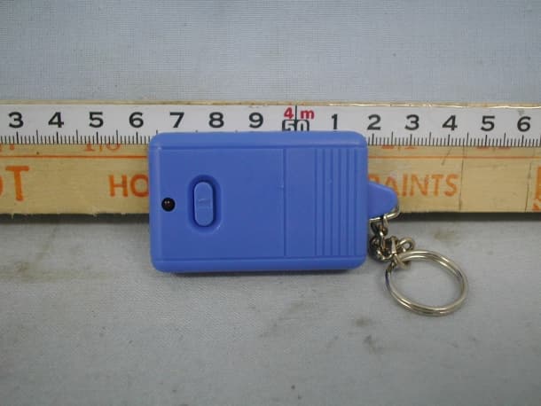
BGA2KTX
Aug 13, 2001Car Alarm Transmitter
Equipment Class
DSC - Part 15 Security/Remote Control Transmitter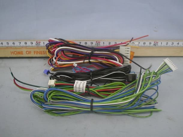
BGA2KRX
Jul 16, 2001Car Alarm Receiver
Equipment Class
CRR - Superregenerative Receiver
BGADF-205
Sep 12, 2000Family Radio Transceiver
Equipment Class
FRF - Part 95 Family Radio Face Held Transmitter