BGAEX8RCar Alarm Receiver
Audiovox Corporation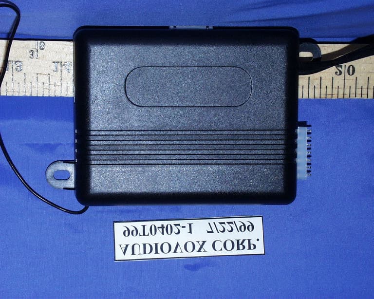
Click to zoom
Application Details
- Equipment Class
- CRR - Superregenerative Receiver
- Date of Grant
- Oct 06, 1999
- Application Purpose
- Original Equipment
- Date of Application
- Aug 03, 1999
- Equipment Note
- Car Alarm Receiver
- Frequency Range
- 302.00000000 - 302.00000000
- Company
- Audiovox Corporation
- Country
- United States
Documents & Files
Document Text
Text extracted from the exhibit documents filed with the FCC. Open a document above to read the original.
ID Label/Location Info
PROPOSED FCC ID LABEL AND LOCATION AUDIOVOX CORPORATION This device complies with Part 15 of the FCC Rules. Operation is subject to the following two conditions: (1) this device may not cause harmful interference, and (2) this device must accept any interference received, including interference that may cause undesired operation. FCC ID: BGAEX8R FCC ID LABEL FCC ID
Test Report
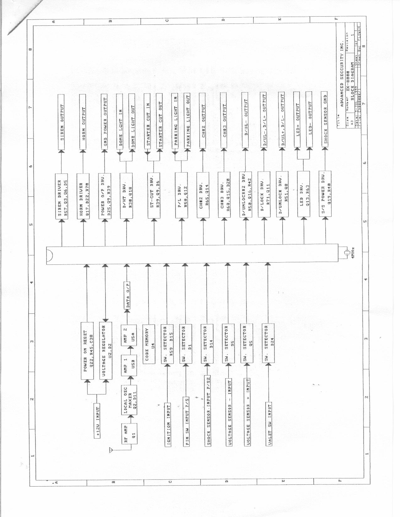
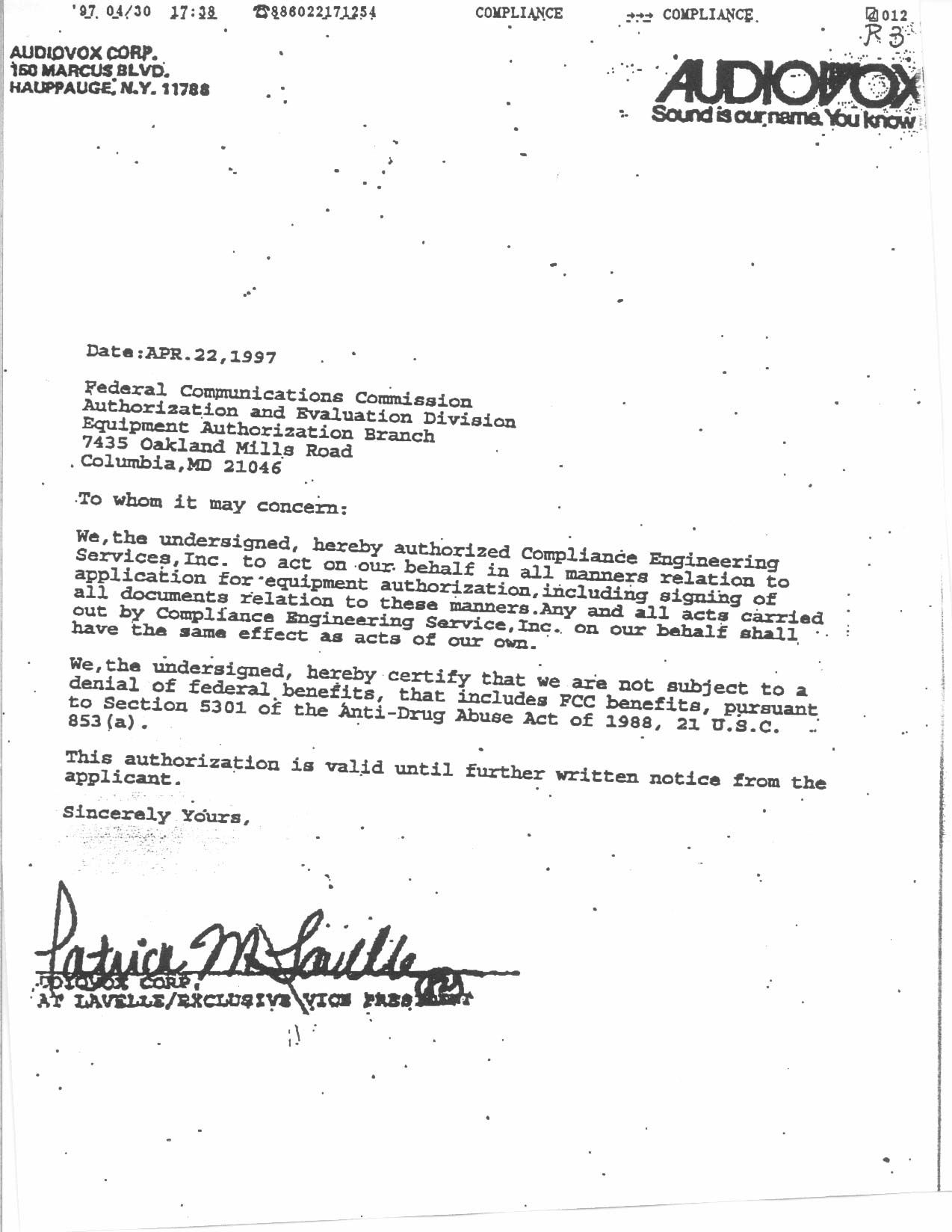
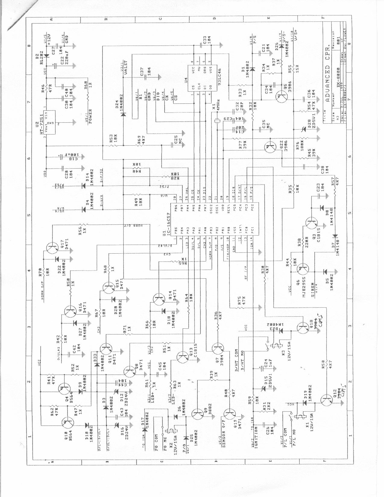
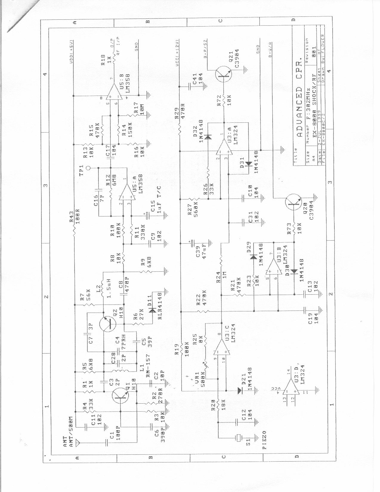
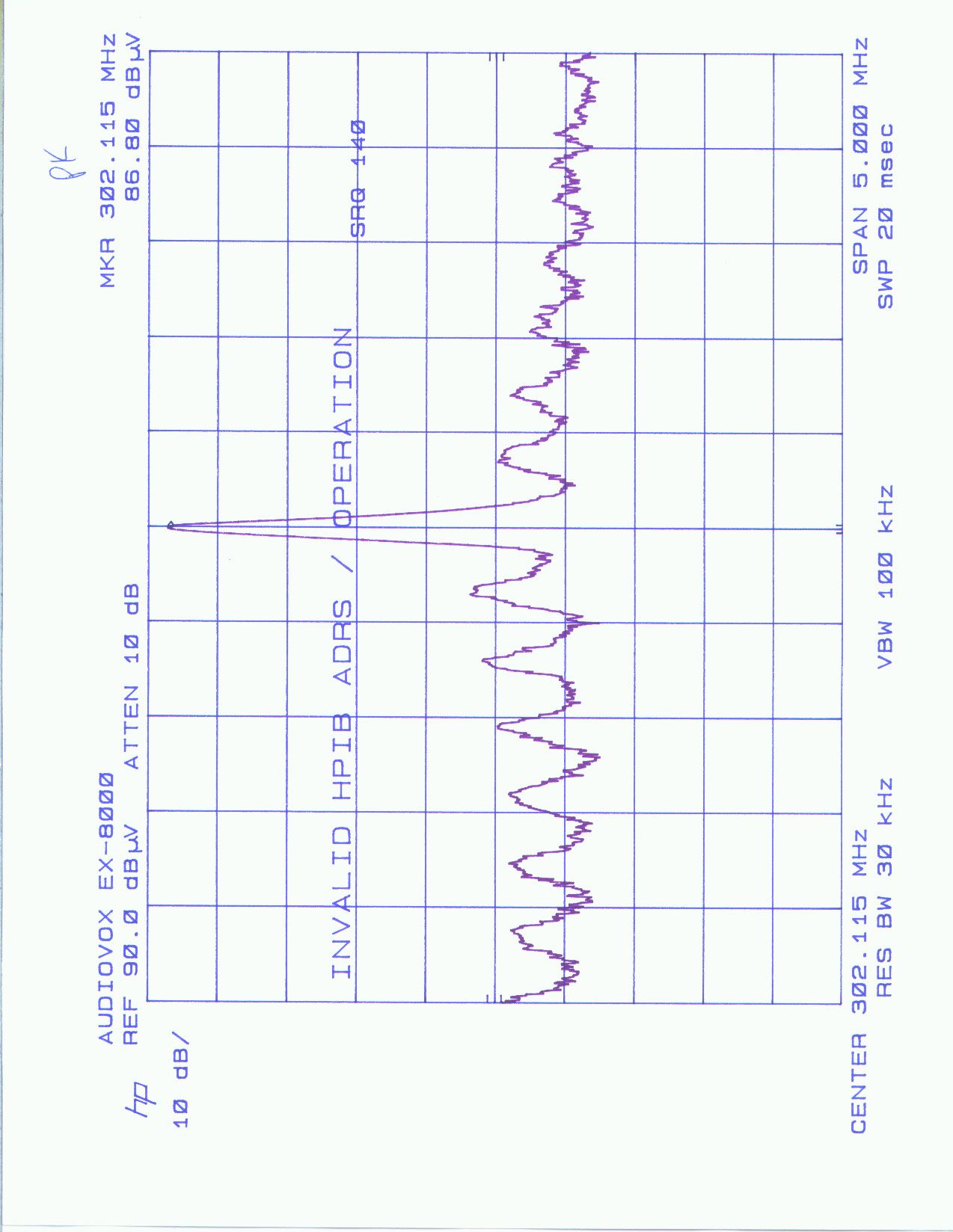
ELECTROMAGNETIC EMISSIONS COMPLIANCE REPORT CERTIFICATION TO FCC PART 15 REQUIREMENTS for UNINTENTIONAL RADIATOR 302 MHz RECEIVER MODEL: EX-8000 FCC ID: BGAEX8R REPORT NO: 99T0402-1 DATE: JULY 13, 1999 Prepared for AUDIOVOX CORPORATION 150 MARCUS BOULEVARD HAUPPAUGE, NY 11788 U.S.A. Prepared by COMPLIANCE ENGINEERING SERVICES, INC. 1366 BORDEAUX DRIVE SUNNYVALE, CA 94089, USA TEL: (408) 752-8166 FAX: (408) 752-8168 TABLE OF CONTENTS 1. VERIFICATION OF COMPLIANCE.................................................................................... 1 2. PRODUCT DESCRIPTION .................................................................................................... 2 3. TEST FACILITY ...................................................................................................................... 2 4. MEASUREMENT EQUIPMENT USED................................................................................ 2 5. TEST CONFIGURATION....................................................................................................... 3 6. TESTS CONDUCTED..............................................................................................................3 7. CONDUCTED EMISSION TEST PROCEDURE................................................................. 3 8. RADIATED EMISSION TEST PROCEDURE .................................................................... 4 9. COHERENT TESTS ................................................................................................................ 4 10. EQUIPMENT MODIFICATIONS........................................................................................ 4 11. TEST CONFIGURATION PHOTOS (RADIATED EMISSION TEST).......................... 5 TEST DATA • Fundamental Frequency Plot • Radiated Emission Data Proposed FCC ID Label......................... Exhibit 1 Agent Authorization Letter.................... Exhibit 2 User Manual................................... Attachment A Block Diagram/Schematics...................... Attachment B REPORT NO:99T0402-1 DATE: JULY 13, 1999 FCC ID:BGAEX8R PAGE NO: COMPLIANCE CONSULTING SERVICESCCS DOCUMENT NO: CCSUP4021B 1366 BORDEAUX DRIVE, SUNNYVALE CA 94089TEL:(408)752-8166 FAX:(408)752-8168 This report shall not be reproduced except in full, without written approval from CCS. 1 1. VERIFICATION OF COMPLIANCE COMPANY NAME : AUDIOVOX CORPORATION 150 MARCUS BOULEVARD HAUPPAUGE, NY 11788 U.S.A. CONTACT PERSON : PAT LAVELLE / EXECUTIVE VICE PRESIDENT TELEPHONE NO. : (516) 231-7750 EUT DESCRIPTION : 302 MHz RECEIVER MODEL NAME/NUMBER : EX-8000 FCC ID : BGAEX8R DATE TESTED : JULY 13, 1999 REPORT NUMBER : 99T0402 TYPE OF EQUIPMENT SECURITY EQUIPMENT (UNINTENTIONAL RADIATOR) EQUIPMENT TYPE 302 MHz SUPERREGENERATE RECEIVER MEASUREMENT PROCEDURE ANSI 63.4 / 1992 LIMIT TYPE CERTIFICATION FCC RULE CFR 47, PART 15.109 The above equipment was tested by Compliance Engineering Services, Inc. for compliance with the requirements set forth in CFR 47, PART 15. This said equipment in the configuration described in this report shows that maximum emission levels emanating from equipment are within the compliance requirements. MIKE C.I. KUO / VICE PRESIDENT COMPLIANCE ENGINEERING SERVICES, INC. REPORT NO:99T0402-1 DATE: JULY 13, 1999 FCC ID:BGAEX8R PAGE NO: COMPLIANCE CONSULTING SERVICESCCS DOCUMENT NO: CCSUP4021B 1366 BORDEAUX DRIVE, SUNNYVALE CA 94089TEL:(408)752-8166 FAX:(408)752-8168 This report shall not be reproduced except in full, without written approval from CCS. 2 2. PRODUCT DESCRIPTION AUDIOVOX CORP., Model EX-8000 is the receiving portion of a multi-purpose security device. The associated Transmitter is manufactured by Audiovox Corp., Model No: FOB-OE3B, FCC ID: BGAOE3B. 3. TEST FACILITY The 3 meter open area test site and conducted measurement facility used to collect the radiated data is located at 561F Monterey Road, Morgan Hill, California, U.S.A. A detailed description of the test facilities was submitted to the Commission on May 27, 1994. The measuring instrument which was utilized in performing the tests documented herein has been calibrated in accordance with the manufacturer's recommendations for utilizing calibration equipment which is traceable to recognized national standards. 4. MEASUREMENT EQUIPMENT USED Manufacturer Model Number Description Cal Due Date H.P. 8640B Signal Generator (0.5 - 1024 MHz) 08/99 H.P. 8566B Spectrum Analyzer (100Hz - 22GHz) 09/99 EMCO 3146 Antenna (200-1000 MHz) 10/99 H.P. 8447D Preamplifier (0.1 - 1300 MHz) 09/99 ARA DRG-18/A Antenna(1 - 18GHZ) 12/99 H.P. 8449B Preamplifier (1-26.5GHZ) 03/00 REPORT NO:99T0402-1 DATE: JULY 13, 1999 FCC ID:BGAEX8R PAGE NO: COMPLIANCE CONSULTING SERVICESCCS DOCUMENT NO: CCSUP4021B 1366 BORDEAUX DRIVE, SUNNYVALE CA 94089TEL:(408)752-8166 FAX:(408)752-8168 This report shall not be reproduced except in full, without written approval from CCS. 3 5. TEST CONFIGURATION Set signal generator to transmit at 302 MHz. The receiver receives the signal. 6. TESTS CONDUCTED CFR 47, 15.107 CODUCTED TESTS CONDUCTED WHEN DEVICE CONNECTED TO AC LINE CFR 47, 15.109 RADIATED EMISSION TESTS CONDUCTED AT 3 METERS 7. CONDUCTED EMISSION TEST PROCEDURE The EUT is located so that the distance between the boundary of the EUT and the closest surface to the LISN is 0.8m. Conducted disturbance shall be measured between the phase lead and the ground, and between the neutral lead and the ground. The frequency 0.450 - 30 MHz shall be investigated. Set the EMI receiver to PEAK detector setting and sweep continuously over the frequency range to be investigated. Set resolution bandwidth to 9kHz minimum. Connect EMI receiver input cable to LINE 1 RF measurement connection on the LISN. Connect a 50ohm terminator to the unused RF connection on the LISN. For each mode of EUT operation, maximize emissions readings by manipulating cable and wire positions. Record the configuration for each EUT power cord which produces emissions closest to the limit. Repeat the same procedure…
Text truncated - open the document above for the full version.
Contact Information
Applicant
Patrick Lavelle(Exclusive Vice President)
[email protected]516 231-7750
Technical Contact
Compliance Engineering ServicesMike C. I. Kuo
[email protected]408-752-8166
1366 Bordeaux Drive · Sunnyvale, California · United States
Non-Technical Contact
Compliance Engineering ServicesAnne Liang
[email protected]408-752-8166
Test Firm
Compliance Certification Services IncSteve Cheng
Technical Specifications
| # | Rule Parts | Frequency Range | Power Output |
|---|---|---|---|
| 1 | 15B | 302 MHz - 302 MHz | - |
Other Applications from Audiovox Corporation

BGA-XMXP05
Apr 01, 2007XM Satellite RX with FM Transmitter
Equipment Class
DXX - Part 15 Low Power Communication Device Transmitter
BGA-XMXP03
Aug 24, 2006XM Radio RX and FM TX
Equipment Class
DXX - Part 15 Low Power Communication Device Transmitter
BGA-XMXP01
Sep 12, 2005Low Power Transmitter
Equipment Class
DXX - Part 15 Low Power Communication Device Transmitter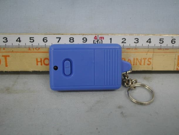
BGA2KTX
Aug 13, 2001Car Alarm Transmitter
Equipment Class
DSC - Part 15 Security/Remote Control Transmitter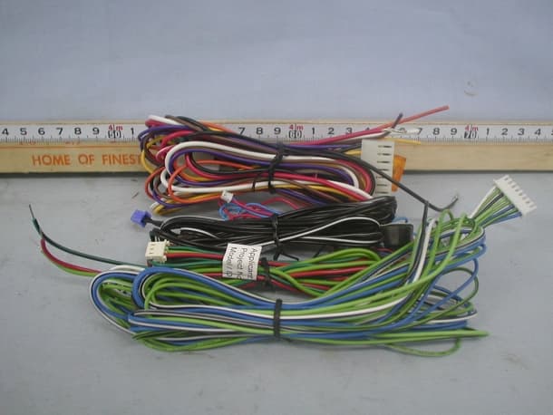
BGA2KRX
Jul 16, 2001Car Alarm Receiver
Equipment Class
CRR - Superregenerative Receiver