BIO460Digital Sudio to Transmitter Link
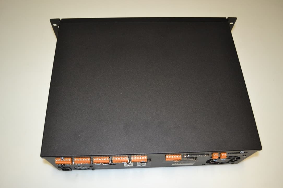
TFT Inc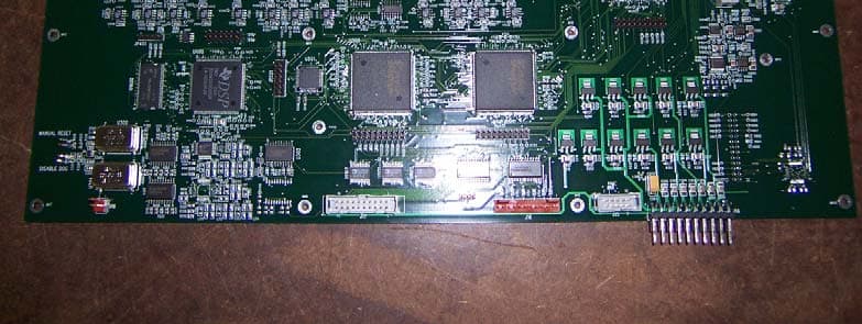
Click to zoom
Application Details
- Equipment Class
- TNB - Licensed Non-Broadcast Station Transmitter
- Date of Grant
- Feb 07, 2005
- Application Purpose
- Original Equipment
- Date of Application
- Feb 07, 2005
- Equipment Note
- Digital Sudio to Transmitter Link
- Frequency Range
- 944.00000000 - 952.00000000
- Company
- TFT Inc
- Country
- United States
Documents & Files
Document Text
Text extracted from the exhibit documents filed with the FCC. Open a document above to read the original.
Users Manual
SECTION I GENERAL INFORMATION 1.1 INTRODUCTION This Model 460 Digital STL Transmitter User’s Guide is arranged in eight sections, as follows: Section I: General Information A general description of the DIGITAL Transmitter, its specifications, general information on the FCC designator, warranty and damage claim procedures, and technical support information. Section II Getting To Know Your Model 460 and Related Equipment Overview of the various system components of the DIGITAL Transmitter and related equipment. Control and Indicator functions, basic component functions, and their interconnection. Section III: Pre-Installation Checkout Some basic test methodology on the DIGITAL Transmitter and its related equipment. The user should find it useful to perform the tests in this section with all the DIGITAL Transmitter equipment on a lab bench. Section IV: Programming The DIGITAL Transmitter Detailed description of setup procedures of various DIGITAL Transmitter system parameters, as well as enabling of optional features. Section V: Installation Instruction for installing and adjusting various system components of the DIGITAL Transmitter. Section VI: Theory of Operation TBD. Section VIII: Theory of Operation Basic description of I/O control circuits. Section VIII: Maintenance and Repair Describes routine maintenance procedures and tools and equipment requirements. 1.2 EQUIPMENT DESCRIPTION The DIGITAL Transmitter is part of a combined Digital Studio to Transmitter Link that provides broadcasters with six uncompressed program channels and a data channel to meet the requirements of consolidated operations. It provides the maximum number of high quality program channels over a single RF channel. The TFT Digital STL consists of a transmitter and receiver pair that accommodates up to three AES/EBU (stereo) inputs or up to six discrete audio channels. The transmitter has a 2-Watt output and delivers them uncompressed in a configurable digital method to the receiver. Sample rates of 32, 44.1, and 48 ks/s are supported. The method of modulation is a function of the number of channels and sample rate and is configurable from a front panel jack that can be connected to a laptop PC. The RF system is frequency agile and set by software in the transmitter and receiver. The frequency and input/output configuration of both the transmitter and receiver can be set for optimum values of threshold and modulation via a laptop PC that can be connected to a modem. User-friendly software with a graphical user interface (GUI) is provided with each system. The transmitter and receiver can be remotely controlled over an internet or LAN connection. 1.3 SPECIFICATIONS The DIGITAL Transmitter performance and physical specifications are listed in Table 1.3-1. 1-1 Table 1.3-1. DIGITAL TRANSMITTER Specifications SYSTEM Frequency................................940-960 MHz (other frequencies available) Step Size..................................12.5 kHz Frequency Stability..................± 5 ppm (±0.0005)% Occupied Bandwidth............... ≤ 500 kHz I/O............................................AES/EBU (XLR, 110 Ω) Analog (XLR, 600Ω) Linear Channels Sample Rate (ks/s) Modulation Type 6 32 256 QAM 4 48 256 QAM 4 44.1 256 QAM 4 32 64 QAM 2 48 16 QAM 2 44.1 16 QAM 2 32 BPSK Frequency Response................0.5 Hz to 22.5 kHz (48 ks/s) 0.5 Hz to 15 kHz (32 ks/s) Distortion.................................< 0.005% at 1 kHz Noise........................................> 92 dB Dynamic Range.......................90 dB static Crosstalk..................................< 80 dB Time Delay..............................< 1 msec Data Channel...........................9600 baud, 9-pin, RS-232 TRANSMITTER Output Power...........................> 2 Watts (nominal) Output Impedance....................50 . Output Connector....................Type N (female) PC Interface.............................Front Panel 9-pin RS-232 Analog Audio Inputs...............600/10 k Ω selectable Analog Levels..........................– 10 to + 18 dBm adjustable AES/EBU Inputs......................110 Ω (Transformer Balanced) MECHANICAL AND ENVIRONMENTAL Dimensions..............................19 x 3.5 x 17 (inches) 48.3 x 8.9 x 43.2 (cm) Weight.....................................20 lbs. (9 kg) AC Power Requirements .........120/240 VAC 50/60 Hz Transmitter...............................100 Watts Operating Temperature............0° to +50° C. 1-2 1-3 1.4 FCC DESIGNATOR Type Certification under FCC Part 74 has been submitted. The FCC emission designator is 500KD7W. The FCC ID is BIO460. 1.5 WARRANTY INFORMATION The following warranty policy and limitations are applicable to the Model 460 Digital STL Transmitter. TFT, Inc. warrants each manufactured Model Digital Studio to Transmitter Link Transmitter to meet published specifications and to be free from defects in material and workmanship. TFT will repair or replace, at its expense, for a period of one (1) year from the date of shipment of equipment, all parts which are defective from faulty material or workmanship. This Warranty does not cover equipment which has been misused and/or altered by the user. Units found to be defective during the warranty period shall be returned to TFT with transportation charges prepaid by the BUYER. It is expressly agreed that replacement and repair shall be the sole remedy of the SELLER with respect to any non-conforming equipment and parts thereof, and shall be in lieu of any other remedy available by applicable law. All returns to the factory must be authorized in advance by TFT. Upon examination by the factory, if any DIGITAL Transmitter Equipment is found to be defective, the unit will be repaired and returned to the BUYER with transportation charges prepaid by TFT during the warranty period. Transportation charges for the Encoder and Decoder units found to be defective within the first 30 days of the warranty period will be paid both ways by TFT . Transportation charges for…
Text truncated - open the document above for the full version.
Cover Letter(s)
Confidentiality Request 1/28/05 AmericanTCB 6731 Whittier Ave. McLean, VA 22101 FCC ID: BIO460 In regards the exhibits submitted in support of the application for FCC ID: BIO460, please classify the following as confidential: • Schematics • Parts List These exhibits contain technical information which Socket Communications deems to be sensitive and proprietary. Therefore this information cannot be published. If this information were to be made public it could be used to the disadvantage of the applicant in the marketplace. Bob Cole President EMCE Engineering (Authorized Agent for TFT, Inc.)
Internal Photos
FCC ID: BIO460 EUT Photos: Internal Top Cover Removed Main PCB – Component Side Main PCB – Solder Side TX PCB – Component Side TX PCB - Solder Side P/S PCB – Component Side P/S PCB - Solder Side Display PCB – Component Side Display PCB – Solder Side
Operational Description
FCC ID: BIO460 Operational Description The following Operational Description appears in Section 1.2 of the User’s Manaul: 1.2 EQUIPMENT DESCRIPTION The DIGITAL Transmitter is part of a combined Digital Studio to Transmitter Link that provides broadcasters with six uncompressed program channels and a data channel to meet the requirements of consolidated operations. It provides the maximum number of high quality program channels over a single RF channel. The TFT Digital STL consists of a transmitter and receiver pair that accommodates up to three AES/EBU (stereo) inputs or up to six discrete audio channels. The transmitter has a 2-Watt output and delivers them uncompressed in a configurable digital method to the receiver. Sample rates of 32, 44.1, and 48 ks/s are supported. The method of modulation is a function of the number of channels and sample rate and is configurable from a front panel jack that can be connected to a laptop PC. The RF system is frequency agile and set by software in the transmitter and receiver. The frequency and input/output configuration of both the transmitter and receiver can be set for optimum values of threshold and modulation via a laptop PC that can be connected to a modem. User-friendly software with a graphical user interface (GUI) is provided with each system. The transmitter and receiver can be remotely controlled over an internet or LAN connection.
RF Exposure Info
To whom it may concern: 1-28-2005 The reasons that TFT Model 460 is not covered by 47CFR 2.1091(b), 47CFR 2.1091(c), 47CFR 2.1093(b) follows: The equipment under test (EUT) is designed to be rack mounted in a fixed location. It is not easily moved from location to another because antenna, power, control and monitoring cables must be removed before re-location. The EUT cannot be operated while in transit from one fixed location to another. The EUT is physically used in a rack mount enclosure. The EUT is normally connected to a transmission line which conducts RF energy from the unit to an antenna, generally located many meters above the body of any possible user or nearby persons. Therefore the EUT is not qualified for the 47CFR2.1091(b). The EUT is not a mobile device as defined by 47CFR2.1091(b). The EUT is designed to be used so that the radiating structure (antenna) is located several meters above the equipment on a support structure. Therefore the EUT is not qualified for the 47CFR2.1093(b) The main consideration is that the EUT is not a mobile or portable device, such as a wireless telephone or portable computer with an RF transmitter. The EUT is generally deployed in a commercial, professional and secured environment and restricted from the vicinity of the general public or passers-by. Best Regards Bob Cole President EMCE Engineering
Test Report
EMCE Report Number: ER050105-3 Date: 2/2/05 Page: 1 of 15 Electromagnetic Compatibility Test Report Model: 460 (Digital STL Transmitter) EMCE Test Report Number: ER050105-3 Dated: 2/2/05 Prepared for: TFT, Inc. 1330 Concourse Drive San Jose, CA 95131 Prepared by: EMCE Engineering 44366 South Grimmer Blvd Fremont, Ca 94538 EMCE Report Number: ER050105-3 Date: 2/2/05 Page: 2 of 15 TABLE OF CONTENTS Paragraph Title Page 1.0 Purpose 3 2.0 Description of Test Sample 3 3.0 Disposition of Test Specimen 3 4.0 Narrative Aspect 3 4.1 Conclusion 3 4.2 Camera, Model ELOP EMC Testing Summary 4 LIST OF TABLES TABLE Title Page 1 Summary of Test Results 4 LIST OF APPENDICES Appendix Title Page A Test Data 6-28 B Test Setup Photographs 29-38 C EUT Photographs 39-50 D Test Equipment List 51-53 E EMCE Laboratory Accreditations 54-55 EMCE Report Number: ER050105-3 Date: 2/2/05 Page: 3 of 15 1.0 PURPOSE Measurements were performed on the TFT, Inc. Digital STL Transmitter Model 460 (hereinafter referred to as the “EUT”) to determine the electromagnetic emissions as they relate to Part 74 of CFR 47. Measurements were performed at the test facilities of: EMCE Engineering 44366 S. Grimmer Blvd Fremont, Ca 94538 See appendix D for list of laboratory accreditations. 2.0 DESCRIPTION OF TEST SAMPLE Testing was conducted to determine the individual EMC characteristics of the Digital STL Transmitter (Model 460, no S/N). The TFT 460 Digital STL Transmitter transmits on one RF channel between 944.0 MHz and 952.0 MHz per CFR 47, 74.502(b). 3.0 DISPOSITION OF TEST SPECIMEN Upon completion of the specified EMC tests the EUT was returned to TFT, Inc. in San Jose, CA, by TFT personnel. 4.0 NARRATIVE ABSTRACT 4.1 Conclusions After completion of all EMC measurements, all measured data was reviewed and compared with the applicable sections from CFR 47, Part 74 (i.e., Applicable sections of 47CFR 74: 74.1 and Subpart E which consists of: 74.501, 74.502, 74.503, 74.531, 74.532, 74.533, 74.534, 74.535, 74.536, 74.537, 74.550, 74.551, 74.561, 74.562, 74.564, and 74.582), and test methods described in CFR 47, Parts 2 and 74. Individual test results will be presented in this section of the report. Table 1 summarizes the test results. EMCE Report Number: ER050105-3 Date: 2/2/05 Page: 4 of 15 TABLE 1: SUMMARY OF TEST RESULTS CFR Section Title Comments Results 2.1046, 74.534 RF Power Output PASSED 2.1047, 74.535 Modulation Characteristics PASSED 2.1049, 74.535 Occupied Bandwidth PASSED 2.1051 Spurious Emissions PASSED 2.1055, 74.561 Frequency Stability PASSED 2.1057 Investigation of Frequency Spectrum PASSED 4.2 EMC Testing Summary 4.2.1 RF Power Output (CFR 2.1046, 74.534) Test results may be found in Appendix A. 4.2.2 Modulation Characteristics (CFR 2.1047, 74.535) Test results may be found in Appendix A 4.2.3 Occupied Bandwidth (CFR 2.1049, 74.535) Test results may be found in Appendix A. 4.2.4 Spurious Emissions (CFR 2.1051) Test results may be found in Appendix A. 4.2.5 Frequency Stability (CFR 2.1055, 74.561) Test results may be found in Appendix A 4.2.6 Radiated Spurious Emissions / Investigation of Frequency Spectrum (CFR 2.1053, 2.1057) Test results may be found in Appendix A EMCE Report Number: ER050105-3 Date: 2/2/05 Page: 5 of 15 APPENDIX A Test Data For Digital STL Transmitter M/N: 460 EMCE Report Number: ER050105-3 Date: 2/2/05 Page: 6 of 15 RF Power Output (CFR 2.1046, 74.534), Modulation Characteristics (CFR 2.1047, 74.535), Occupied Bandwidth (CFR 2.1049, 74.535) Test Location: EMCE Engineering •44366 S. Grimmer Blvd • Fremont, CA 94538 • 510-490-4307 Customer: TFT, Inc. Specification: TFT Mask 950 Work Order #: Date:12/20/2004 Test Type: Radiated Scan Time:10:24:39 AM Equipment: Digital STL Transmitter Sequence#:21 Manufacturer: TFT, Inc. Tested By:Bob Cole Model: 460 S/N: N/A Test Equipment: Function S/N Calibration Date Cal Due Date Asset # HP 8593EM Spectrum Analyzer N/A 08/11/2004 08/11/2005 123 Equipment Under Test (* = EUT): Function Manufacturer Model # S/N Digital STL Transmitter TFT, Inc. 460 N/A Support Devices: Function Manufacturer Model # S/N Attenuator WJ 3514-20 N/A Test Conditions / Notes: 2W power out Transducer Legend: T1=20 dB Attenuator T3=Attenuator TX Cable T2=Chamber Receive Cable to 1 GHz Measurement Data: Reading listed by margin. Test Distance: None # Freq Rdng T1 T2 T3 Dist Corr Spec Margin Polar MHz dBμV dB dB dB dB Table dB dB dB Ant 1 950.014M 108.5 +0.0 139.7 140.0 -0.3 None +20.0 +5.5 +5.7 EMCE Report Number: ER050105-3 Date: 2/2/05 Page: 7 of 15 . EMCE Report Number: ER050105-3 Date: 2/2/05 Page: 8 of 15 Spurious Emissions (CFR 2.1051) Test Location: EMCE Engineering •44366 S. Grimmer Blvd • Fremont, CA 94538 • 510-490-4307 Customer: TFT, Inc. Specification: TFT 2W 1-26GHz Work Order #: Date:12/20/2004 Test Type: Radiated Scan Time:4:50:14 PM Equipment: Digital STL Transmitter Sequence#:2 Manufacturer: TFT, Inc. Tested By:Scott Model: 460 S/N: N/A Test Equipment: Function S/N Calibration Date Cal Due Date Asset # AH Systems DR Horn Antenna 1291 07/28/2004 07/28/2006 389 HP 8593EM Spectrum Analyzer N/A 08/11/2004 08/11/2005 123 Equipment Under Test (* = EUT): Function Manufacturer Model # S/N Digital STL Transmitter* TFT, Inc. 460 N/A Support Devices: Function Manufacturer Model # S/N Attenuattor WJ 3514-20 N/A Test Conditions / Notes: ANTENNA CONDUCTED SCAN Transducer Legend: Measurement Data: Reading listed by margin. Test Distance: None # Freq Rdng Dist Corr Spec Margin Polar MHz dBμV dB dB dB dB Table dBμV/mdBμV/m dB Ant 1 3800.985M 65.1 +0.0 65.1 130.0 -64.9 Vert 2 2851.617M 64.5 +0.0 64.5 130.0 -65.5 Vert 3 5701.725M 59.9 +0.0 59.9 130.0 -70.1 Vert 4 1900.245M 59.0 +0.0 59.0 130.0 -71.0 Vert 5 4750.353M 56.7 +0.0 56.7 130.0 -73.3 Vert 6 7600.460M 52.7 +0.0 52.7 130.0 -77.3 Vert 7 9501.200M 46.1 +0.0 46.1 130.0 -83.9 Vert 8 8551.832M 44.5 +0.0 44.5 130.0 -85.5 Vert EMCE Report Number: ER050105-3 Date: 2/2/05 Page: 9 of 15 9 7347.830M 44.2 +0.0 44.2 130.0 -85.8 Vert 10 7576.400M 44.0…
Text truncated - open the document above for the full version.
Test Setup Photos
FCC ID: BIO460 Test Set-up Photos Antenna Conducted Emissions FCC ID: BIO460 Test Set-up Photos Spurious Radiated Emissions
Contact Information
Applicant
Darryl Eugene Parker(President)
Technical Contact
EMCE EngineeringBob Cole
[email protected]510-490-4307
44366 South Grimmer Blvd. · Fremont, California · United States
Test Firm
EMCE Engineering, Inc.Bob Cole
Technical Specifications
| # | Rule Parts | Frequency Range | Power Output | Emission | Tolerance |
|---|---|---|---|---|---|
| 1 | 74 | 944 MHz - 952 MHz | 2 W | 500KD7W | 0.0005000000 % |
Other Applications from TFT Inc
BIOEAS911PLUS
Mar 05, 2013EAS Encoder/Decoder
Equipment Class
EAD - Part 11 Emergency Alert Devices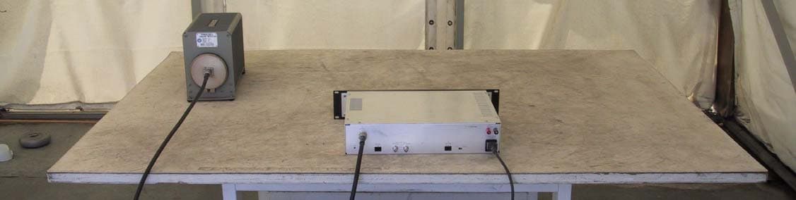
BIO5290
May 29, 2005ANALOG STUDIO TO TRANSMITTER LINK
Equipment Class
TBC - Licensed Broadcast Station Transmitter
BIOEAS911D
Jul 22, 2002Emergency Alert System Decoder
Equipment Class
EAD - Part 11 Emergency Alert DevicesBIOEAS911
Dec 08, 1996Emergency Alert System Encoder/Decoder
Equipment Class
EAD - Part 11 Emergency Alert DevicesBIOEAS930
Mar 25, 1996EAS/AM/FM/Weather Radio Receiver
Equipment Class
CXX - Communications Rcvr for use w/ licensed Tx and CBs