BIOEAS911DEmergency Alert System Decoder
TFT Inc
Click to zoom
Application Details
- Equipment Class
- EAD - Part 11 Emergency Alert Devices
- Date of Grant
- Jul 22, 2002
- Application Purpose
- Original Equipment
- Date of Application
- Jul 22, 2002
- Equipment Note
- Emergency Alert System Decoder
- Frequency Range
- 88.00000000 - 108.00000000
- Company
- TFT Inc
- Country
- United States
Documents & Files
Document Text
Text extracted from the exhibit documents filed with the FCC. Open a document above to read the original.
Users Manual
ii To whom it may concern: June 4, 2002 TFT, Inc. is a manufacturer of EAS Encoders/Decoders, who now seeks Type Certification of an EAS Decoder (only) under FCC Rule Part 11. On January 31, 1996, TFT, Inc. was granted Type Certification on an Emergency Alert System Encoder/Decoder, FCC Identifier BIOEAS911, File No. 31010/EQU 4-3-4. The Decoder (only) for which TFT now seeks Type Certification is part of the original Certification Application made on November 10, 1995. Several of the Part 11 Compliance Tests for that application are incorporated in this new application for an EAS Decoder (only) device, which does not function as an Encoder as well. In order to accomplish this, TFT has removed several circuits and components from the original Encoder/Decoder in order to disable and defeat its functionality as an EAS Encoder. Because the overall construction of the unit is not materially changed, all Decoder tests conducted for the original application remains at no change and may apply to this application as well. Best regards, Edmund Fong Executive Vice President- TFT Inc. EAS 911D Decoder Preliminary Data Sheet Features • Decodes and forwards EAS emergency messages • Two self-contained receivers • RS-232 Output for character generator interface • Built-in impact printer • Digital audio recorder • Front panel mounted speaker • LCD display • Password protected • Automatic or manual operation • FCC Type Notification Pending General Until now a decoder-only for broadcast and cable applications of the Federal Communications Commission’s (FCC) Emergency Alert System (EAS) has not existed. The EAS 911D is a decoder only, based on the proven performance of the TFT EAS 911 line of EAS Encoder/Decoders, that permits a broadcaster or cable operator to receive and forward EAS messages. These operations may be handled either automatically for unmanned situations or manually with the assistance of an operator. The EAS 911D has many of the features of the EAS 911 Encoder/Decoders, including a built-in impact printer, character generator interfaces, a lighted numeric keypad, practice operation, and many visual indicators. The EAS 911D also features easy set-up and operation with a combination of LCD and lighted key displays that guide an operator or installer through each step. Decoder Section The decoder section of the EAS 911D is programmed in the same fashion as the EAS 911 encoder/decoders. Password protection allows an operator to set up all parameters associated with decoding EAS messages, including setting the current date and time, setting the station time zone, automatic observance of daylight savings time, and the station’s FIPS (Federal Information Processing System) code. The decoder can be programmed for automatic forwarding of EAS messages when user-selected criteria of event selection and location are met. The event code and location codes of an incoming EAS message are compared electronically to lists stored in setup of the EAS 911D to decide whether a message should automatically forwarded. If there is a match of both the event field and at least one of the location fields, the message will be automatically forwarded. Also in setting up the EAS 911D several interfaces are available for video character generators. These character generators are available in both analog and digital versions. Some interfaces even permit setting of character generator parameters from the EAS 911D. The user can also select whether text for the Required Weekly Test (RWT) is sent to the character generator or not. In Setup Mode, the EAS 911D can also record a short voice announcement (used for cable television system compliance), set the alert time-out, and enable a one-button method of manually forwarding a message. Receiver Section Built into the EAS 911D are two receiver modules for receiving the two FCC mandated monitoring assignments. These receivers are frequency agile for both AM and FM broadcast and can be configured in any combination if specified at time of order. The frequency for each receiver is set with rotary DIP switches behind an access panel on the front of the unit. All standard broadcast frequencies can be digitally set. Front Panel The EAS 911D front panel is laid out to guide the installer or operator through all the functions necessary to program and operate the unit. In addition to the lighted numeric keypad, the front panel also has other pushbuttons for password, cancel, practice, header send, EOM send, message waiting acknowledgment, manual forwarding, mode switching, and review of both the header and audio portions of an EAS message. Indicators for receiver signal levels, an alert relay closure, an on-air relay closure, and auto/man functions clearly show status of the decoder at a single glance. A speaker key permits audio monitoring of the two built-in receivers and the digital audio recorder. The speaker key also changes the function of the LCD to a bargraph to provide a visual indication of receiver operation. Rear Panel Connectors for RF inputs to the receivers, speaker/printer inhibit, balanced audio output, on-air relay, message alert relay, and digital ports are located on the rear. A professional 120 VAC/60 Hz power and fuse receptacle are also provided. Note: This device has not been authorized as required by the rules of the Federal Communications Commission. This device is not, and may not be offered for sale or lease, or sold or leased, until authorization is obtained. Contents subject to change without notice. ii P/N 5004-EAS911D REV. A June 2002 EQUIPMENT SERIAL NO. __________ SHIPMENT DATE _________________ MODEL EAS911D EMERGENCY ALERT SYSTEM EAS DECODER USER’S GUIDE TFT, INC. 2243 RINGWOOD AVENUE, SAN JOSE, CA 95131 TEL: (408) 943-9323 Service Department Ext. 300 FAX: (408) 432-9218 ii EAS 911D EAS DECODER The EAS DECODER is a combined Emergency Alert System (EAS) Decoder and Receivers in single unit that permits broadcasters, cablecasters and emergency managers …
Text truncated - open the document above for the full version.
Cover Letter(s)
American Telecommunications Certification Body Inc. 6731 Whittier Ave, McLean, VA 22101 July 10, 2002 RE: FCC ID: BIOEAS911D Attention: Bob Cole I have a few comments on this Application. 1 Records from the FCC prior to 1999 are not accessible for review. Please provide all appropriate documentation for review including internal photos, and external photos. 2 Please provide the letter requesting confidentiality of the technical description and the schematics. 3 The test report “TFT Part 2-911D EAS Decoder Part 11 Compliance Test.pdf” is unreadable. Please provide a readable report. 4 The test report “TFT Part 3-911D EAS Decoder Part 11 Compliance Test.pdf” is unreadable. Please provide a readable report. Dennis Ward mailto:[email protected] The items indicated above must be submitted before processing can continue on the above referenced application. Failure to provide the requested information may result in application termination. Correspondence should be considered part of the permanent submission and may be viewed from the Internet after a Grant of Equipment Authorization is issued. Please do not respond to this correspondence using the email reply button. In order for your response to be processed expeditiously, you must submit your documents through the AmericanTCB.com website. Also, please note that partial responses increase processing time and should not be submitted. Any questions about the content of this correspondence should be directed to the sender.
External Photos
Radiated Emissions Test Setup (Rear View) Conducted Emissions Test Setup
ID Label/Location Info
FCC ID Label FCC ID: BIOEAS911D
Internal Photos
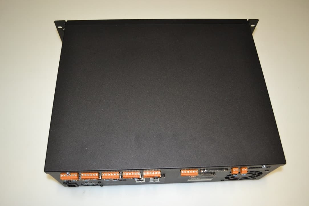
EUT Front View EUT Rear View EUT Internal View Power Supply PCB Top View Power Supply PCB Bottom View Main PCB Top View Main PCB Bottom View
Operational Description
9-1 SECTION IX THEORY OF OPERATION 9.1 The EAS Information Super Highway The Emergency Alert System (EAS) is a nationwide network of radio and television broadcast and cable facilities that can originate or receive and forward (re-transmit) event- and location-specific Emergency Alert messages. Alert messages can originate from the White House, state and local safety agencies, Emergency Operation Centers (EOC), and the National Weather Service (85% of alerts are weather related). When an agency issues an Alert, it transmits an EAS header and message to local AM, FM, and TV stations and cable systems which, in turn, broadcast the message to the general public if the message matches the local requirements. The public can receive alert messages in a matter of seconds and can react quickly to impending emergencies. The EAS message contains digitally encoded event and location information in addition to a normal voice or text announcement. The encoded information permits the network of broadcast and cable stations to decode messages and forward them automatically or manually to a specific area affected by the emergency alert. 9.2 The EAS DECODER: An Overview The EAS DECODER is similar to a smart telephone answering machine. It receives and screens messages on one or two, records and stores them, and forwards selected messages manually or automatically. The digital header in the incoming message is decoded and translated, then displayed on the Liquid Crystal Display (LCD) and logged on the printer. The event and location data is compared with the data stored in the Setup memory to determine if it should be forwarded. If the alert message is to be forwarded, the EAS DECODER inserts a new I.D. code and re-transmits it, along with a two-tone Attention Signal, the recorded voice message and an End Of Message signal. Forwarding can occur automatically or after operator intervention. Refer to Figure 9.2 for a simplified block diagram of the EAS DECODER. Digital Voice Recorder EAS Encoder EAS Message Memory Compare User Programmed Memory FSK Decoder Audio Channel Audio OutBroadcast Transmitter Yes: Auto Forward No: Ignore EAS CASTER Figure 9.2, EAS DECODER Block Diagram 9-2 9.3 A Closer Look: Detailed System Block Diagram The EAS DECODER system consists of the Main Board, the Encoder and Decoder keyboards, the LCD Display Assembly, the Digital Voice Recorder, the Comm Expander and the Printer. Figure 1 in Appendix A illustrates the EAS DECODER system blocks in detail. 9.4 Main Board (Figure 2, Appendix A) The EAS DECODER Main Board consists of three major system blocks: Audio Loop-Through and Switching, Digital Signal Processor/CPU, and Input/Output Control. 9.4.1 Audio Loop Through and Switching (Figure 2, Appendix A) The audio buffering, switching and control section is illustrated on sheet 1 of the Main Board schematic drawing (6601-4060). U1 and U2 provide two balanced input amplifiers for the Channel 1 and 2 audio inputs. Analog switches U3, U8 and U10 route audio signals to and from the inputs, outputs and voice recorder. U4 and U5 are Coders/Decoders (CODECs) that convert the audio signals to digital data, and vice-versa. U7 provides two buffer amplifiers at the outputs of the CODECs. U11 is the internal speaker amplifier; U12 provides a balanced audio EAS message output. 9.4.2 Digital Signal Processor/CPU (Figure 2, Appendix A) The Digital Signal Processor (DSP) section and its related logic is illustrated on sheet 2 of the schematic drawing (6601-4060). U14 is a Texas Instruments TMS320C26 digital signal processor that performs all encoding and decoding functions, and controls all I/O activity. U13 is a Field Programmable Gate Array (FPGA). It generates all internal timing signals and performs all internal digital signal routing. U15 is a real-time clock and provides battery backed-up memory for long term storage of setup information. U16 and U18 are the system random access memory (RAM); U17 and U19 are the system read-only program memory. U21 is a reset circuit and watchdog timer. 9.4.3 Input/Output Control (Figure 2, Appendix A) Input/Output buffering and control for system peripherals and related equipment, is illustrated on sheet 3 of the schematic drawing (6601-4060). U25 through U29 are latches that control the printer, liquid crystal display (LCD), four port communication expander, audio multiplexers and relays. U23 controls the On-Air and Alert relays. U22 and U30 provide RS-232 inputs and outputs. 9.5 Left Section Key Pad (Figure 4, Appendix A) U501, U505. U509, U503, U507 and U511 in series form a 48-bit serial-to-parallel shift register that is used to illuminate the 40 encoder board LEDs. The bits of LED data are shifted in to the keyboard by the I/O control section, above, and then enabled to illuminate or flash the LEDs. U512, U510, U508, U506, U504 and U502 in series form a 48-bit parallel-to-serial shift register that is used to sense the 41 encoder key switches. The bits of switch data are shifted out of the encoder keyboard by the I/O control section, above, and are then interpreted by the DSP/CPU. 9-3 9.6 Right Section Key Pad (Figure 6, Appendix A) U601 and U603 in series form a 16-bit serial-to-parallel shift register that is used to illuminate the 12 decoder board LEDs. The bits of LED data are shifted in to the keyboard by the I/O control section, and then enabled to illuminate or flash the LEDs. U604 and U602 in series form a 16-bit parallel-to-serial shift register that is used to sense the ten decoder key switches. The bits of switch data are shifted out of the decoder keyboard by the I/O control section, above, and are then interpreted by the DSP/CPU. 9.7 LCD Display Assembly The LCD Display Assembly is a 16-character back-lit display with contrast controlled by setup software. The LCD assembly is controlled by the FPGA through an 8-bit parallel data interface at U26 on the main board. 9.8 Digital Voice Recorder (Figure 8, Appendix A) U3 is a sampling analog-to-di…
Text truncated - open the document above for the full version.
Test Report
CERTIFICATE OF COMPLIANCE APPLICABLE SPECIFICATION: 47 CFR PART 2, SUBPART J, PARAGRAPH 2.902 Verification Equipment Authorization Part 15, Subpart B – Unintentional Radiators Paragraph 15.101(a) Verification of Class A Digital Device Report Number: 2121-1 Date of Report: 22 May 2002 I hereby certify that the measurements shown on this report were made in accordance with the procedures of American National Standards Institute (ANSI) Specification C63.4-1992. The voltages conducted along its power leads and electric fields radiated by the equipment listed below meets the Commissions Limits for a Class A Personal Computer Peripheral. Tests were performed on 21 May 2002. Company: TFT Incorporated Street Address: 2243 Ringwood Ave. City, State & ZIP San Jose, CA 95131 Equipment under Test: Emergency Alert System Decoder Model Number: EAS 911D Serial Number: EMI Unit EMCE Engineering, Inc has been place on the Federal Communications Commission’s list of recognized facilities for Parts 15 and 18 DoC approvals. Per the request of EMCE Engineering, the facility has been added to the list of those who perform Measurement Services for the public on a fee basis. This list is published periodically and is also available on the FCC World Wide Web. Additionally, EMCE Engineering has been approved by the National Institute for Science and Technology under the NVLAP program. EMCE Engineering, assumes no responsibility for the continuing validity of test data when the Equipment under Test is not under the continuous physical control of EMCE. The signature below attests to the fact that all measurements reported herein were performed by myself or were made under my supervision, and are correct to the best of my knowledge and belief as of the date specified. I assume full responsibility for the completeness of these measurements and vouch for the qualifications of all persons taking them. Tests were conducted by qualified EMCE Engineering personnel utilizing test equipment maintained in a “current” state of calibration with traceability to NIST. Note • This report or certificate does not represent endorsement by NVLAP or any agency of the US Government. • This report or certificate shall not be reproduced except in full without the written approval of the issuer. Certified by: EMCE Engineering, Inc. Bob Cole President 44366 S. Grimmer Boulevard, Fremont, CA 94538 Report Number: 2121-1 Date: 22 May 2002 Page: 2 of 47 ELECTROMAGNETIC INTERFERENCE TEST REPORT Report Number: 2121-1 Report Date: 22 May 2002 Applicable Specification: 47 CFR Part 15, Subpart B, Paragraph 15.101 Verification of a Class A Digital Device Equipment under Test: Emergency Alert System Decoder Model Number: EAS 911D Serial Number: EMI Unit Prepared for: TFT Incorporated 2243 Ringwood Ave. San Jose, CA 95131 Prepared by: Bob Cole EMCE Engineering, Inc. 44366 S. Grimmer Blvd. Fremont, CA 94538 Phone: 510-490-4307 Fax: 510-490-3441 Note • This report or certificate does not represent endorsement by NVLAP or any agency of the US Government. • This report or certificate shall not be reproduced except in full without the written approval of the issuer. Report Number: 2121-1 Date: 22 May 2002 Page: 3 of 47 TABLE OF CONTENTS Paragraph Title Page 1.0 SCOPE 5 1.1 Objective 5 1.2 Description of EUT 5 1.3 Results/Modifications 5 1.4 Test Limits 5 2.0 APPLICABLE DOCUMENTS 6 2.1 FCC Document 6 2.2 Other Documents 6 3.0 GENERAL SETUP AND TEST CONDITIONS 6 3.1 Test Facility 6 3.2 Description of Open- Field Test Site 8 3.3 Site Attenuation 8 3.4 Ground Plane (Ground Screen) 8 3.5 Input Power for EUT 8 3.6 Accessory Equipment Precautions 9 3.7 Ambient Interference 9 3.8 Personnel 9 3.9 Use of Interference Measuring Equipment 9 3.10 Calibration of Measuring Equipment 10 4.0 PREPARATION OF EUT FOR TEST 10 4.1 Identification of EUT 10 4.2 Setup of EUT 10 4.3 Peripherals Connected 11 5.0 DETAILED MEASUREMENTS 11 5.1 Conducted Emissions, Power Leads, 450kHz to 30MHz 11 5.1.1 Test Results 12 5.1.2 Test Instrumentation 12 5.1.3 Recommendations 12 5.2 Radiated Emissions Test, 30MHz to 1000MHz 13 5.2.1 Vertical Polarization Measurements 14 5.2.2 Horizontal Polarization Measurements 14 5.2.3 Test Results 14 5.2.4 Test Instrumentation 15 5.2.5 Recommendations 15 Report Number: 2121-1 Date: 22 May 2002 Page: 4 of 47 LIST OF FIGURES Figure Title Page 1 EMCE Test Site Layout 7 LIST OF APPENDICES Appendix Title Page A EMI Measurement With the Automatic Spectrum 16 Analyzer B FCC Facility Certification and NVLAP Accreditation 24 C Test Data Sheets 30 D Photographs of Test Setup 35 E FCC Labeling and User Information 46 Report Number: 2121-1 Date: 22 May 2002 Page: 5 of 47 1.0 SCOPE This test report describes the equipment setup, test methods employed and results obtained during EMI testing of a Class A Digital Devices category as defined in Part 15, Subpart A, paragraph 15.3 (h). The tests described herein measured the RF radiated (RFI Field Strength) and power line conducted (RFI Noise Voltage) emissions of the equipment under test (EUT) as installed and operated in a typical setup. The tests conformed to the measurement and test site requirements of ANSI C63.4-1992. 1.1 Objective The tests described herein were performed to establish that the EUT is capable of compliance with the Verification requirements of Part 15, Subpart B, paragraph 15.101 for Unintentional Radiators (Class A Digital Device). 1.2 Description of EUT The EUT is an Emergency Alert System Encoder/Decoder, Model Number: EAS 911, Serial Number: EMI Unit, manufactured by TFT Incorporated. The EUT contained the following options: No Options. 1.3 Results/Modifications The EUT passed FCC Class A conducted and radiated emissions tests. No modification was necessary. The manufacturer may declare the EUT as complying with the FCC interference requirements. FCC labeling and user information is found in Appendix E herein. 1.4 Test Limits FCC Class A conduction and radiation limits are as follows: Conducted Emis…
Text truncated - open the document above for the full version.
Test Setup Photos
Report Number: 2121-1 Date: 22 May 2002 Page: 35 of 47 APPENDIX D PHOTOGRAPHS OF TEST SETUPS PHOTOGRAPHS OF EUT Report Number: 2121-1 Date: 22 May 2002 Page: 36 of 47 Photograph 1. Radiated Emissions Test Setup (Front View) Report Number: 2121-1 Date: 22 May 2002 Page: 37 of 47 Photograph 2. Radiated Emissions Test Setup (Rear View) Report Number: 2121-1 Date: 22 May 2002 Page: 38 of 47 Photograph 3. Conducted Emissions Test Setup Report Number: 2121-1 Date: 22 May 2002 Page: 39 of 47 Photograph 4. EUT Front View Report Number: 2121-1 Date: 22 May 2002 Page: 40 of 47 Photograph 5. EUT Rear View
Contact Information
Applicant
Darryl Eugene Parker(President)
Technical Contact
EMCE EngineeringBob Cole
[email protected]510-490-4307
44366 South Brimmer Blvd · Fremont, California · United States
Non-Technical Contact
EMCE EngineeringBob Cole
[email protected]510-490-4307
Test Firm
EMCE Engineering, Inc.Bob Cole
Technical Specifications
| # | Rule Parts | Frequency Range | Power Output | Tolerance |
|---|---|---|---|---|
| 2 | 11 | 88 MHz - 108 MHz | - | % |
Other Applications from TFT Inc
BIOEAS911PLUS
Mar 05, 2013EAS Encoder/Decoder
Equipment Class
EAD - Part 11 Emergency Alert Devices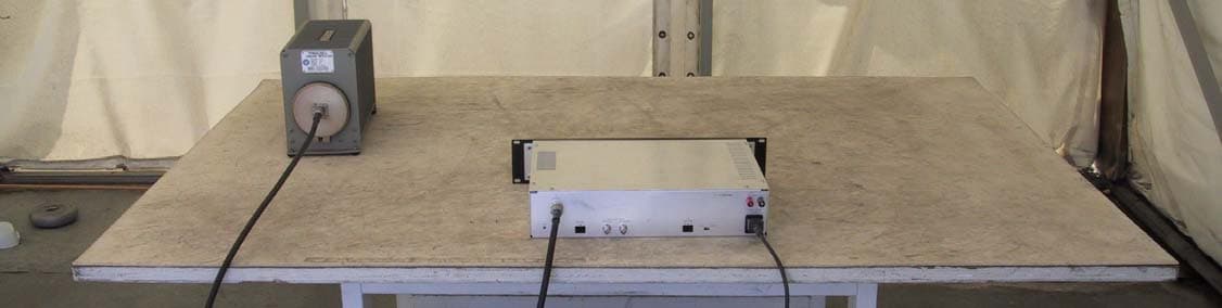
BIO5290
May 29, 2005ANALOG STUDIO TO TRANSMITTER LINK
Equipment Class
TBC - Licensed Broadcast Station Transmitter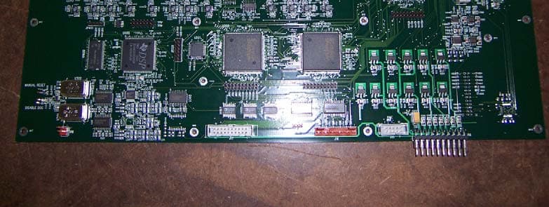
BIO460
Feb 07, 2005Digital Sudio to Transmitter Link
Equipment Class
TNB - Licensed Non-Broadcast Station TransmitterBIOEAS911
Dec 08, 1996Emergency Alert System Encoder/Decoder
Equipment Class
EAD - Part 11 Emergency Alert DevicesBIOEAS930
Mar 25, 1996EAS/AM/FM/Weather Radio Receiver
Equipment Class
CXX - Communications Rcvr for use w/ licensed Tx and CBs