BIOEAS911PLUSEAS Encoder/Decoder
TFT Inc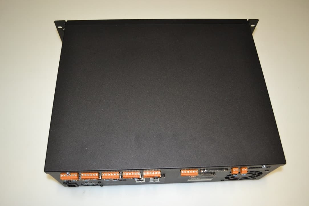
Click to zoom
Application Details
- Equipment Class
- EAD - Part 11 Emergency Alert Devices
- Date of Grant
- Mar 05, 2013
- Application Purpose
- Original Equipment
- Date of Application
- Mar 05, 2013
- Equipment Note
- EAS Encoder/Decoder
- Company
- TFT Inc
- Country
- United States
Documents & Files
Document Text
Text extracted from the exhibit documents filed with the FCC. Open a document above to read the original.
Users Manual
P/N 5004-EAS911+ REV. B January 2013 EQUIPMENT SERIAL NO. SHIPMENT DATE MODEL EAS911+ EAS-CAP USER’S GUIDE TFT, INC. 1953 Concourse Drive San Jose, CA 95131-1708 TEL: (408) 943-9323 FAX: (408)432-9218 EMAIL: [email protected] i CONTENTS SECTION I - GENERAL INFORMATION Paragraph Title Page 1.1 EQUIPMENT DESCRIPTION .............................................................................................................................. 1-1 1.2 SPECIFICATIONS. ................................................................................................................................................ 1-1 1.3 FCC COMPLIANCE STATEMENTS........................................................................................ 1-4 1.4 WARRANTY INFORMATION ............................................................................................................................ 1-4 1.5 CLAIMS FOR DAMAGE IN SHIPMENT ............................................................................................................ 1-4 1.6 TECHNICAL SUPPORT ....................................................................................................................................... 1-4 SECTION II – PRE-INSTALLATION CHECKOUT 2.1 UNPACKING AND INSPECTION ....................................................................................................................... 2-1 2.2 FRONT PANEL INDICATORS ............................................................................................................................ 2-1 2.3 REAR PANEL CONNECTORS ............................................................................................................................ 2-2 2.4 INTERNAL JUMPERS .......................................................................................................................................... 2-3 SECTION III - INSTALLATION Paragraph Title Page 3.1 INTRODUCTION .................................................................................................................................................. 3-1 3.2 MOUNTING AND CONNECTION (ANALOG INSERT) .................................................................................. 3-1 3.3 MOUNTING AND CONNECTION (DIGITAL INSERT) ................................................................................. 3-21 SECTION IV – THEORY OF OPERATION 4.1 INTRODUCTION .................................................................................................................................................. 4-1 4.2 SYSTEM BLOCK DIAGRAM .............................................................................................................................. 4-1 4.3 DETECTION FRAMING CONTROL AND DETECTION VERIFICATION ...................................................... 4-1 4.4 DELAY AND SWITCH.......................................................................................................................................... 4-2 4.5 DETECTION AND CONTROL ............................................................................................................................. 4-3 4.6 POWER SUPPLY ................................................................................................................................................... 4-3 SECTION V – INSTALLATION 5.1 INTRODUCTION............................................................................................................ 5-1 5.2 ENCODER AUDIO OUTPUT LEVEL ADJUSTMENT............................................................ 5-1 ii CONTENTS (Continued) 5.3 DECODER AUDIO INPUT LEVEL ADJUSTMENT............................................................ 5-2 5,5 DIGITAL INTERFACE (RS232)..................................................................................... 5-2 5.6 DIGITAL INTERFACE (RS232)......................................................................................5-2 5.7 DIGITAL INTERFACE (RS485)..................................................................................... 5-3 5.8 THE ON-AIR RELAY .................................................................................................. 5-3 5.9 THE ALERT RELAY ...................................................................................................5-3 5.11 SPEAKER INHIBIT ................................................................................................... 5-3 5.15 MOVING MESSAGE SIGNS ........................................................................................ 5-3 SECTION VI – OPERATION 6.1 INTRODUCTION ...................................................................................................... 6-1 6.2 NETWORK CONNECTION ......................................................................................... 6-1 6.3 OPERATING MODE DETAILS...................................................................................... 6-2 6.4 CAP SET UP MODE PROGRAMMING .......................................................................... 6-3 SECTION VII – THEORY OP OPERATION 7.1 GENERAL DESCRIPTION AND PURPOSE .................................................................... 7-1 SECTION VIII – MAINTENANCE AND REPAIRS 8.1 INTRODUCTION........................................................................................................ 8-1 8.2 TOOL AND TEST EQUIPMENT REQUIREMENTS ......................................................... 8-1 8.3 ROUTINE MAINTENANCE ......................................................................................... 8-1 8.5 DIAGNOSTICS AND REPAIRS .................................................................................... 8-2 8.7 TROUBLE SHOOTING ............................................................................................. 8-2 8.8 TFT SERVICE DEPARTMENT .................................................................................. 8-3 APPENDICES APPENDIX A - ENGINEERING DRAWINGS APPENDIX B - PARTS LISTS APPENDIX C…
Text truncated - open the document above for the full version.
Cover Letter(s)
SCS-F18: Project and Product Certification Representative Authorization Letter Page 1 of 2 Rev 3.0 775 Montague Expressway Milpitas, CA 95035 Tel: 408-526-1188 Fax: 408-526-1088 Email: [email protected] Project and Product Certification Representative Authorization Letter Reason for Amendment (current / obsolete) Revision History Approved Date From To Initial Release (obsolete) 1.0 1.0 Nov-14-2006 Revised wording (obsolete) 1.0 2.0 Sept–25-2007 Updated company template (current) 2.0 3.0 Jan-31-2012 SCS-F18: Project and Product Certification Representative Authorization Letter Page 2 of 2 Rev 3.0 1/7/2013 To: SIEMIC, INC. 775 Montague Expressway, Milpitas, CA 95035 USA Dear Sir/Madam, Re: Project and Product Certification Representative Authorization Letter We, EMCE Engineering, hereby authorize SIEMIC, INC. to act as a Certification Body for certifying for the following project(s): FCC ID: BIOEAS911PLUS Product: EAS Encoder/Decode Model: EAS 911+ We affirm that between SIEMIC and EMCE Engineering, any difference in understanding, including test plan, measurement methods, applicable standards and relevant procedures and processes have been resolved prior to commencement of testing activities. Sincerely, Bob Cole / President EMCE Engineering 44366 S. Grimmer Blvd, Fremont, CA 94538 510-490-4307 / 510-490-3441 Fax / [email protected]
Cover Letter(s)
SCS-F19: Confidentiality Request Letter Page 1 of 3 Rev 3.0 775 Montague Expressway Milpitas, CA 95035 Tel: 408-526-1188 Fax: 408-526-1088 Email: [email protected] Confidentiality Request Letter Reason for Amendment (current / obsolete) Revision History Approved Date From To Initial Release (obsolete) 1.0 1.0 Nov-14-2006 Adding CFR 2.459 (obsolete) 1.0 2.0 August – 11 - 2008 Updated company template & Added text box (current) 2.0 3.0 Jan-31-2012 SCS-F19: Confidentiality Request Letter Page 2 of 3 Rev 3.0 1/25/2013 To: Federal Communications Commission Authorization and Evaluation Division 7435 Oakland Mills Road Columbia, MD Subject: Permanent Confidentiality Request for FCC ID: BIOEAS911PLUS We hereby request confidential treatment of information accompanying this application as outlined below: - Block Diagram - Schematics - Operational Description The above materials contain trade secrets and proprietary information not customarily released to the public. The public disclosure of these materials may be harmful to the applicant and provide unjustified benefits to its competitors. The applicant understands that pursuant to Section 0.457 & 0.459 of the Rules, disclosure of this application and all accompanying documentation will not be made before the date of the Grant for this application. Sincerely, Client’s signature Client’s name / title : Bob Cole / President Contact information / address: 44366 S. Grimmer Blvd, Fremont, CA 94538 [email protected] / 510-490-4307 SCS-F19: Confidentiality Request Letter Page 3 of 3 Rev 3.0 1/25/2013 To: Federal Communications Commission Office of Engineering and Technology Equipment Authorization Division 7345 Oakland Mills Road Columbia, Maryland 21046 Subject: Short Term Confidentiality Request for FCC ID: BIOEAS911PLUS To Whom It May Concern: Pursuant to sections 0.457 and 0.459 of CFR 47 and to avoid premature release of sensitive information prior to marketing or release of the product to the public, the applicant requests the following documents contained in this certification application be temporarily withheld from public disclosure for an initial period of 45 or 180 days (please check one). - User Manual The above materials contain trade secrets and proprietary information not customarily released to the public. The public disclosure of these materials may be harmful to the applicant and provide unjustified benefits to its competitors. Sincerely, Client’s signature : Client’s name / title : Bob Cole / President Contact information / address : 44366 S. Grimmer Blvd, Fremont, CA 94538 [email protected] / 510-490-4307
External Photos
FCC ID: BIOEAS911PLUS External Photos FCC ID: BIOEAS911PLUS External Photos FCC ID: BIOEAS911PLUS External Photos
ID Label/Location Info
Label Location
Internal Photos
FCC ID: BIOEAS911PLUS Internal Photos Top Cover Removed I/O PCB – Component View FCC ID: BIOEAS911PLUS Internal Photos I/O PCB – Solder Side Font Panel LCD PCB FCC ID: BIOEAS911PLUS Internal Photos Interface PCB / SSD – Top View Interface PCB Mounting FCC ID: BIOEAS911PLUS Internal Photos Main PCB – Top Side Main PCB – Bottom Side
Test Report
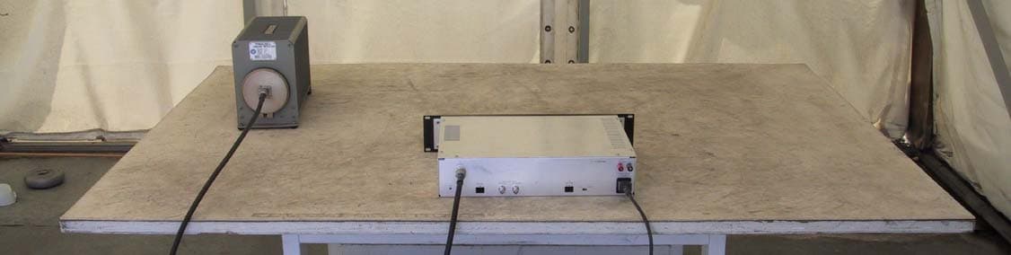
Report #3770-1 12/18/12 Page 1 of 23 Electromagnetic Compatibility Test Report Company Name: TFT, Inc. Equipment Under Test: EAS Encoder / Decoder Model Number: EAS 911+ FCC ID: BIOEAS911PLUS Requirements: 47 CFR Part 2, Subpart J, Paragraph 2.906 47 CFR Part 11, Subpart B – Equipment Requirements Verified by: Bob Cole Authorized Signatory Report #3770-1 Dated: 12/18/12 ACCREDITED BY THE NATIONAL VOLUNTARY LABORATORY ACCREDITATION PROGRAM FOR THE SPECIFIC SCOPE OF ACCREDITATION UNDER LAB CODE #: 200092-0 Report #3770-1 12/18/12 Page: 2 of 23 EMCE Engineering 44366 S. Grimmer Blvd. Fremont, CA 94538 510-490-4307 510-490-3441 Fax Statement of Compliance We, EMCE Engineering, declare under our sole responsibility that the product tested complies with the following listed standards: Equipment under Test: EAS Encoder / Decoder Model Number: PNSD32G-133-610 with sub-assembly 41359-C10-32GOM Serial Number: N/A Report Number: 3770-1 Test Date: 12/18/12 Company: TFT, Inc. Street Address: 1953 Concourse Drive City, State & ZIP San Jose, CA 95133 This Statement of Compliance is based upon compliance of the product with the following FCC Rules: 47 CFR PART 2, SUBPART J, PARAGRAPH 2.906 Part 11, Subpart B – Equipment Requirements Issued by Test Laboratory: Lab Code:200092-0 EMCE Engineering 44366 S. Grimmer Blvd. Fremont, CA 94538 510-490-4307 Office / 510-490-3441 Fax Verified By: Bob Cole Authorized Signatory Report #3770-1 12/18/12 Page: 3 of 23 EMCE Engineering 44366 S. Grimmer Blvd. Fremont, CA 94538 510-490-4307 510-490-3441 Fax Test Location EMCE Electro Magnetic Controlled Environment 44366 S. Grimmer Blvd. Fremont, CA 94538 USA Report #3770-1 12/18/12 Page: 4 of 23 EMCE Engineering 44366 S. Grimmer Blvd. Fremont, CA 94538 510-490-4307 510-490-3441 Fax Table of Contents Accreditation 5 Disclaimer 5 Administrative Data 6 EUT Description 7 Maximum Operating Frequency 7 Testing Configuration 7 Test Summary 8 Test Mode Justification 8 Equipment Modification 8 Test System Details 9 EUT Sample Photos 10 Attachment 1 Emission Results 14 Attachment 2 EMCE NVLAP Accreditation 21 Attachment 3 CFR 47, Part 11 Field Test EMC Susceptibility 23 Test Results Report #3770-1 12/18/12 Page: 5 of 23 EMCE Engineering 44366 S. Grimmer Blvd. Fremont, CA 94538 510-490-4307 510-490-3441 Fax Accreditation EMCE Engineering, has been placed on the Federal Communications Commission’s list of recognized facilities for Parts 15 and 18 DoC approvals. Per the request of EMCE Engineering, the facility has been added to the list of those who perform Measurement Services for the public on a fee basis. This list is published periodically and is also available on the FCC Website. Additionally, EMCE Engineering, has been approved by the National Institute for Standards and Technology under the NVLAP program (Lab Code 200092-0). Disclaimer EMCE Engineering, Inc., assumes no responsibility for the continuing validity of test data when the Equipment under Test is not under the continuous physical control of EMCE. The signature below attests to the fact that all measurements reported herein were performed by myself or were made under my supervision, and are correct to the best of my knowledge and belief as of the date specified. EMCE assumes full responsibility for the completeness of these measurements. Tests were conducted by qualified EMCE Engineering, Inc. personnel utilizing test equipment maintained in a “current” state of calibration with traceability to NIST. This report or certificate does not represent endorsement by NVLAP, NIST or any agency of the US Government. This report or certificate shall not be reproduced except in full without the written approval of the issuer. Report #3770-1 12/18/12 Page: 6 of 23 EMCE Engineering 44366 S. Grimmer Blvd. Fremont, CA 94538 510-490-4307 510-490-3441 Fax Administrative Information Equipment under Test: EAS Encoder / Decoder Model Number: EAS 911+ Serial Number: N/A Report Number: 3770-1 Test Date: 12/18/12 Company: TFT, Inc. Street Address: 1953 Concourse Drive City, State & ZIP San Jose, CA 95133 Report #3770-1 12/18/12 Page: 7 of 23 EMCE Engineering 44366 S. Grimmer Blvd. Fremont, CA 94538 510-490-4307 510-490-3441 Fax EUT DESCRIPTION The equipment under test is a TFT, Inc. EAS Encoder / Decoder M/N: EAS 911+ MAXIMUM OPERATING FREQUENCY EUT operates at the < 108 MHz: Per EN55022, Radiated Emissions must be scanned to a range covering 30 MHz – 1 GHz. TESTING CONFIGURATION The EUT model name EAS 911+ was set up per the applicable specification during EMI testing. Report #3770-1 12/18/12 Page: 8 of 23 EMCE Engineering 44366 S. Grimmer Blvd. Fremont, CA 94538 510-490-4307 510-490-3441 Fax TEST SUMMARY The electromagnetic compatibility requirements on tested model name EAS 911+ for this test are listed below. All results listed in this report are related exclusively to the above- mentioned model as the equipment under test, and confers no endorsement or certification of any other component, host, or subsystem used in the testing configuration. Specification Description Test Results Comments EN55022:2010 CLASS B Conducted Emission Passed EN55022:2010 CLASS B Radiated Emission Passed TEST MODE JUSTIFICATION Test Standard Configuration Info Comments EN 55022 Class B Radiated Emissions EN 55022 Class B Conducted Emissions EQUIPMENT MODIFICATIONS Any modifications installed previous to testing by TFT, Inc. will be incorporated in each production model sold or leased. There were no modifications installed by EMCE Engineering. Report #3770-1 12/18/12 Page: 9 of 23 EMCE Engineering 44366 S. Grimmer Blvd. Fremont, CA 94538 510-490-4307 510-490-3441 Fax TEST SYSTEM DETAILS EUT Model name: EAS Encoder / Decoder Description: EAS 911+ Manufacturer: TFT, Inc. Support Equipment Description Model Number Serial Number Manufacturer Power Cable Description Serial Interface EAS 941A 10101589 TFT, Inc. AC Adapter Modem Modem Blaster C1BF0080649000307HCreative AC Adapter Modem Modem Blaster C1BF00806470…
Text truncated - open the document above for the full version.
Test Report
TFT MODEL EAS911+ Emergency Alert System Encoder/Decoder FCC Part 11 Compliance Tests TFT, Inc. San Jose, California March 5, 2013 Edition 4 Model EAS911+ F CC Part 11 Compli ance Tests, Editi on 4 Page 1 San Jose, CA FCC ID:BIOEAS911PLUS TABLE OF CONTENTS 1. GENERAL INFORMATION Page 5 1.1 Product Description 2. TEST FACILITIES Page 5 2.1 List of Specific Test Equipment 2.2 Lab Test Facility 2.3 Temperature and Humidity Test Facility 2.4 Field Test Facilities 3.. EAS ENCODER COMPLIANCE TESTS 3.1 EAS Encoder Protocol Verification Page 6 3.1.1 Test Objective 3.1.2 Test Block Diagram 3.1.3 Test Methodology 3.1A EAS Encoder Protocol Verification Page 52 §11.32(a)(1) 3 .1A.1 Test Objective 3.1A.2 Test Block Diagram 3.1A.3 Test Methodology 3.2 Encoder Programming Access Verification Page 53 3.2.1 Test Objective 3.2. 2 Test Block Diagram 3.2.3 Test Methodology 3.3 Encoder Input Verification Page 54 3.3.1 Test Objective 3.3.2 Test Block Diagram 3.3.3 Test Methodology 3.4 Encoder Output Verification Page 64A 3.4.1 Test Objective 3. 4.2 Test Block Diagram 3.4.3 Test Methodology 3. 5 Encoder Calibration Support Verification Page 65 3.5.1 Test Objective 3.5.2 Test Block Diagram 3.5.3 Test Methodology 3.6 Encoder Data Retention Verification Page 67 3.6.1 Tes t Objective 3.6.2 Test Block Diagram 3.6.3 Test Methodology 3.7 Encoder Preamble Indicator Verification Page 69 3. 7.1 Test Objective 3. 7.2 Test Block Diagram 3.7.3 Test Methodology 3.8 Encoder Spurious Response Verification Page 71 3.8.1 Test Objective 3.8.2 Test Block Diagram 3.8.3 Test Methodology Model EAS911+ F CC Part 11 Compli ance Tests Page 2 San Jose, CA FCC ID:BIOEAS911PLUS 3.9 Encoder Attention Signal Verification Page 74 3.9.1 Test Objective 3.9.2 Test Block Diagram 3.9 .3 Test Methodology 4. . EAS DECODER COMPLIANCE TESTS 4.1 EAS Decoder Protocol Verification Page 78 4.1.1 Test Objective 4.1.2 Test Block Diagram 4.1.3 Test Methodology 4.2 Decoder Input Verification Page 79 4.2.1 Test Objective 4.2.2 Tes t Block Diagram 4.2.3 Test Methodology 4.3A Decoder Valid Code Verification Page 88 4.3A.1 Test Objective 4.3A.2 Test Block D iagram 4.3A.3 Test Methodology 4.3B Decoder Storage Verification Page 89 4.3B.1 Test Objective 4. 3B.2 Test Block Diagram 4.3B.3 Test Methodology 4.4 Decoder Di splay Verification Page 90 4. 4.1 Test Objective 4.4.2 Test Block Diagram 4.4.3 Test Methodology 4.5 Decoder Indicator Verification Page 91 4.5.1 Test Objective 4.5.2 Test Block Diagram 4.5.3 Test Methodology 4. 6 Decoder Data Retention Verification Page 93 4.6.1 Test Objective 4 .6.2 Test Block Diagram 4.6.3 Test Methodology 4.7 Decoder Output Verification Page 95 4.7.1 Tes t Objective 4.7.2 Test Block Diagram 4.7. 3 Test Methodology 4.8 Decoder Programming Verification Page 96 4.8.1 Tes t Objective 4.8 .2 Tes t Block Diagram 4.8 .3 Test Methodology 4.9 Decoder Rese t Verification Page 98 4.9.1 Test Objective 4.9.2 Test Block Diagram 4.9.3 Test Methodology 4.10 Decoder Message Validity Verification Page 100 4.10.1 Test Objective 4.10.2 Test Block Diagram 4.10.3 Test Methodology 4.11 Decod er EAN Event Override Verification Page 109 4.11 .1 Test Objective 4.11.2 Test Block Diagram 4.11.3 Test Methodology Model EAS911+ F CC Part 11 Compli ance Tests Page 3 San Jose CA FCC ID:BIOEAS911PLUS 1 5. EAS ENCODER/DECODER ENVIRONMENTAL COMPLIANCE TESTS 5.1 Encoder/Dec oder Primary Supply Voltage Variation Verification Page 116 5.1.1 Test Objective 5.1.2 Test Block Diagram 5. 1.3 Test Methodology 5.2 Encoder/Dec oder Operating Temperature and Humidity Verification Page 131 5.2.1 Test Objective 5.2.2 Test Block Diagram 5.2 .3 Test Methodology 5.3 Encoder/Decoder Electromagnetic Field Susceptibility Verification Page 143 5.2.1 Test Objective · 5.2.2 Test Block Diagram 5.2 .3 Test Methodology ATTACHMENTS: USER'S MANUAL PRODUCT LITERATURE EAS ENCODER/DECODER PART 15 COMPLIANCE TESTS LETTER OF AUTHORIZATION Model EAS911+ F CC Part 11 Compli ance Tests Page 4 San Jose, CA FCC ID: BIOEAS911PLUS 1. GENERAL INFORMATION 1.1 Product Description The TFT Model EAS911+ en co de s and decodes messages in accor dance with the newly established Emergency Alert System (EAS) as described in FCC Report and Order and Further Notice of Proposed Rule Making FCC 94-288 that was adopted on November 10, 19 94. The TFT Model EAS911+ is self contained in a 19 " wide by 5” high rack mount enclosure and is in tended to a llow radio, television, and cable broadcasters the ability to send the receive EAS message as required by the FCC. 2. TEST FACILITIES 2.1 List of Specific Test Equipment All equipment maintained by regularly scheduled calibration to meet manufacturer's equipment specifications using manufacturer approved calibration lab practices. TEST EQUIPMENT MANUFACTURER MODEL NUMBER FREQ. RANGE Spectrum Analyzer Signal Hound USB-SA44 10 Hz – 1 GHz Oscilloscope Hewlett Packard 54602B 0 Hz - 150 MHz Printer Brother HL-2040 Multimeter Fluke 8050A Lap top Computer Dell Inspiron 600M Desk top PC Dell Dimension 8300 EAS Encoder/Decoder TFT EAS911 Temperature and Humidity Chamber Tenney 40 AM Field Str. Meter Potomac Instruments FIM-21 AM FIELD SET FM Field Str. Meter Potomac Instruments FIM-71 FM FIELD SET Camera Mino1ta AF-DL Variac Technipower W5MT3A 50 Hz - 60 Hz Storage Oscilloscope Tektronix TDS2024 2.2 Lab Test Facility The laboratory test site collecting data for all tests except field susceptibility is located at: · TFT, Inc. TEL: (408) 943- 9323 1953 Concourse Drive FAX: (408) 432-9218 San Jose CA 95131 All testing performed with 120 VAC, 60Hz wall outlet unfiltered power facilities with ground traceable to central building earth ground. 2.3 Field Test Facilities AM field testing performed at antenna site of: FM field testing performed at antenna site of: KFAX/AM KXSC/FM KTRB/AM San Jose, CA Hayward, CA 2.4 Temperature and Humidity Test Facility Quanta Labs Address: 3190 De La Cruz Blvd., Santa Clara, CA 95054 Model EAS911+ F CC Part 11 Compli ance Tests Page 5 9/4/12 San Jose, CA FC…
Text truncated - open the document above for the full version.
Test Report
Mark Frequency 2083.2Hz (520.8Hz/cycle x4=2083.2Hz) Bit Length = 1.92ms Page 52-2 Space Frequency 1562.5 Hz (520.8Hz /cycle x3 cycles=1562.5Hz) Bit Length = 1.92ms Page 52-3 1 ST Preamble Pause 1 Second Duration Page 52-4 2 nd Preamble Pause 1 second Duration Page 52-5 3 rd Preamble Pause 1 Second Duration Page 52-6 Attention Signal 8 Second Duration Page 52-7 Post-Message Pause 1 Second Duration Minimum Page 52-8 Post-Message before EOM 1 Second Duration Minimum Page 52-9 1st Post Message Preamble Pause 1 Second Duration Page 52-10 2nd Post Message Preamble Pause 1 Second Duration Page 52-11 3rd Post Message Preamble 1 Second Duration Minimum Page 52-12 FCC ID: BIOEAS911PLUS 3.2 Encoder Programming Access Verification 3.2.1 Test Objective The objective of this test is to verify encoder programming access: §11.32(a)(1): Encoder programming. Access to encoder programming shall be prote cted b y a lock o r other security measures and be configured so that authorized personnel c an readily select and program th e EAS Encoder with Originator, Event and Location codes for ei ther manual or automatic operation. 3.2.2 Test Block Diagrams TFT Model EAS911+ Encoder 3.2.3 Test Methodology Pa ssword entry is verified for access to the encoder. A setup password is also verified for the user to gain access to both encoder and decoder programming functions. Password changes require initial password entry, and this is also verified. Model EAS911+ F CC Part 11 Compli ance Tests Page 53 9/4/12 San Jose, CA 3.3 Encoder Input Verification 3.3.1 Test Objective The objective of this test is to verify encoder in put compliance: §11.32(a)(2): Inputs. The encoder sh all have two inputs, one for audio messages and one for data messages (RS-232C with standard protocol and 1200 baud rate). 3.3.2 Test Block Diagrams TFT Model TFT Model EAS911+ EAS911+ Encoder Decoder/Encoder Unit Under Test 3.3.3 Test Methodology The test message ZCZC-PEP-EAN-WAAA/FM - is sent through from the encoder to d ecoder through audio channel 1. Successful decode is verified. The test message ZCZC-PEP-EAN-WAAA/FM - is sent through from the encoder to d ecoder through audio channel 2. Successful decode is verified. The test message ZCZC-PEP-EAN-WAAA/FM - is sent through from the encoder to decoder through the standard protocol da ta channel. Successfu l decode is verified. Model EAS911+ F CC Part 11 Compli ance Tests Page 5 4 2- 15-2013 San Jose, CA FCC ID: BIOEAS911PLUS 3.4 Encoder Output Verification 3.4.1 Test Objective The objective of this test is to verify encoder output compliance: §11.32(a)(3): Outputs. The encoder shall have tw o outputs, one audio and one data port (RS-232C with standard protocol and 1200 baud rate). 3.4.2 Test Block Diagrams TFT Model TFT Model EAS911+ EAS911+ Encoder Decoder/Decoder Unit Under Test 3.4.3 Test Methodology The test message ZCZC-PEP-EAN-WAAA/FM- is sent through from the encoder to d ecoder through audio channel 1. Successful decode is verified. The test message ZCZC-PEP-EAN-WAAA/FM- is sent through from the encoder to d ecoder through audio channel 2. Successful decode is verified. The test message ZCZC-PEP-EAN-WAAA/FM - is sent through from the encoder to decoder through the standard protocol da ta channel. Successfu l decode is verified. Refer to Section 3.3 page 55 to page 64 for test data Model EAS911+ F CC Part 11 Compli ance Tests Page 64A 2- 15-2013 San Jose, CA FCC ID: BIOEAS911PLUS 3.5 Encoder Calibration Support Verification 3.5.1 Test Objective The objective of this test is to verify encoder calibration support compliance: §11.32(a)(4): Calibration. EAS Encoders must pr ovide a means to comply with the modulation l evels requir ed in §11.51(f). §11.51(f): . . . Th e minimum level of modulation for EAS codes, measured at peak modulation levels u sing t he internal calibration output specified in §11.32(a)(4) of this part, shall modulate th e transmitter at no l es s than 80% of full channel modulation limits. Measured at peak modulation levels, each of the Attention Signal to nes shall be calibrated separately to modulate the transmitter at no less than 40%. These two calibrated modulation le vels shall have values that are within 1 dB of each other. 3.5.2 Test Block Diagrams TFT Model EAS911+ Oscilloscope Encoder HP54602B 3.5.3 Test Methodology A steady two tone for system calibration is verified by accessing the test tone menu per the installation and operation manual. Access to a steady alternating FSK mark-space pattern or a steady two tone for system calibration is verified by accessing the tes t tone menu per the installation an d operation manual. The peak to peak level of the FSK and two tone signals are verified to ge within l dB of each other using an oscilloscope. Model EAS911+ F CC Part 11 Compli ance Tests Page 65 9/4/12 San Jose, CA FCC ID: BIOEAS911PLUS + 3.6 Encoder Data Retention Verification 3.6.1 Test Objective The objective of this test is to verify encoder data retention compliance: §11.32(a)(6): Program Data Retention. Program data and codes shall be retained even with the power removed. 3.6.2 Test Block Diagrams TFT Model TFT Model EAS911+ EAS 911 Encoder Decoder 3.6.3 Test Methodology Data retention through power interruptions is verified by ob serving the last ten transmitted EAS messages as recorded on the printer. The indicated time is also calibrated with local time and recorded. Power is then removed for 24 hours. When power is reapplied the la st ten transmitted and received EAS messages are again printed. The time is also recorded and compared with local time. The messages must match before and after power is removed and the time agrees within 5 seconds of the correct time. It is also verified that Event and Location definitions hav e not changed after 24 hours by inspection of the LCD. Model EAS911+ F CC Part 11 Compli ance Tests Page 67 9/4/12 San Jose, CA FCC ID: BIOEAS911PLUS 3.7 Encoder Preamble Indicator Verification 3.7.1 Test Objective The objective …
Text truncated - open the document above for the full version.
Test Report
FCC ID: BIOEAS911PLUS 4.3B Decoder Storage Verification 4.3B.1 Test Objective The objective of this te st is to verify that means for message storage are provided in accordance with: §11.33(a)(3) Storage. Decoders must provide the means to: (i) Record an d store at least tw o minutes of audio or text messages. (ii) Store at le ast 10 preselected header co des for comparison with in co ming header codes. A non-preselected header code that is manually transmitted must be stored for comparison with later incoming header codes. Th e header codes of the last ten received valid messages which still have valid time periods must be stored for comparison with the in coming valid hea der codes of la ter messages. The header codes will be deleted fr om storage as th eir valid time periods expire. 4.3B.2 Test Block Diagram TFT Model TFT Model EAS911+ EAS911+ Encoder Decoder 4.3B.3 Test Methodology Verification of two minutes or more of audio or t ex t transmission storage is p erformed in c onjunction with an external tape recorder. The message alert relay is observed to activate upon successful decode and verification of an EAS message which in tu rn activates a remote tape recorder. A two minutes voice message id produced that is followed by an EOM transmission The EOM causes the message alert relay to deac tivate and thereby stop the recorder. . The verification of message storage is accomplished by placing the decoder in automatic forwar d mode and sending a se quence of ten dif fer ent mess ages that are all set to expire at the same time. E…
Text truncated - open the document above for the full version.
Contact Information
Applicant
Darryl Eugene Parker(President)
Test Firm
Universal Compliance Labs dba EMCE EngineeringBob Cole
Technical Specifications
| # | Rule Parts | Frequency Range | Power Output |
|---|---|---|---|
| 1 | 11 | - | - |
Other Applications from TFT Inc
BIO5290
May 29, 2005ANALOG STUDIO TO TRANSMITTER LINK
Equipment Class
TBC - Licensed Broadcast Station Transmitter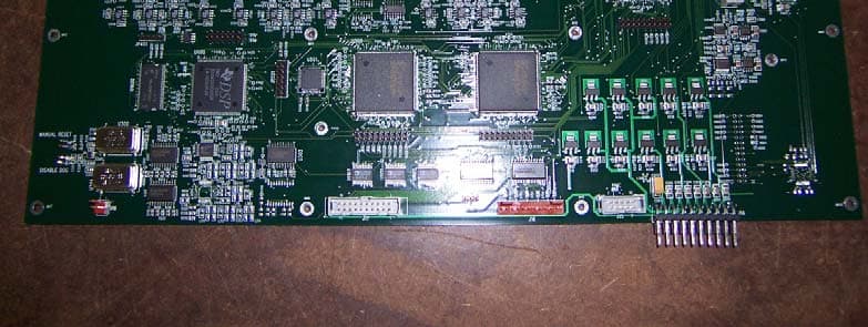
BIO460
Feb 07, 2005Digital Sudio to Transmitter Link
Equipment Class
TNB - Licensed Non-Broadcast Station Transmitter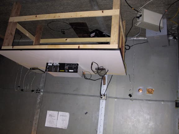
BIOEAS911D
Jul 22, 2002Emergency Alert System Decoder
Equipment Class
EAD - Part 11 Emergency Alert DevicesBIOEAS911
Dec 08, 1996Emergency Alert System Encoder/Decoder
Equipment Class
EAD - Part 11 Emergency Alert DevicesBIOEAS930
Mar 25, 1996EAS/AM/FM/Weather Radio Receiver
Equipment Class
CXX - Communications Rcvr for use w/ licensed Tx and CBs