BMTMBSR100MWRepeater
EMCEE Broadcast Products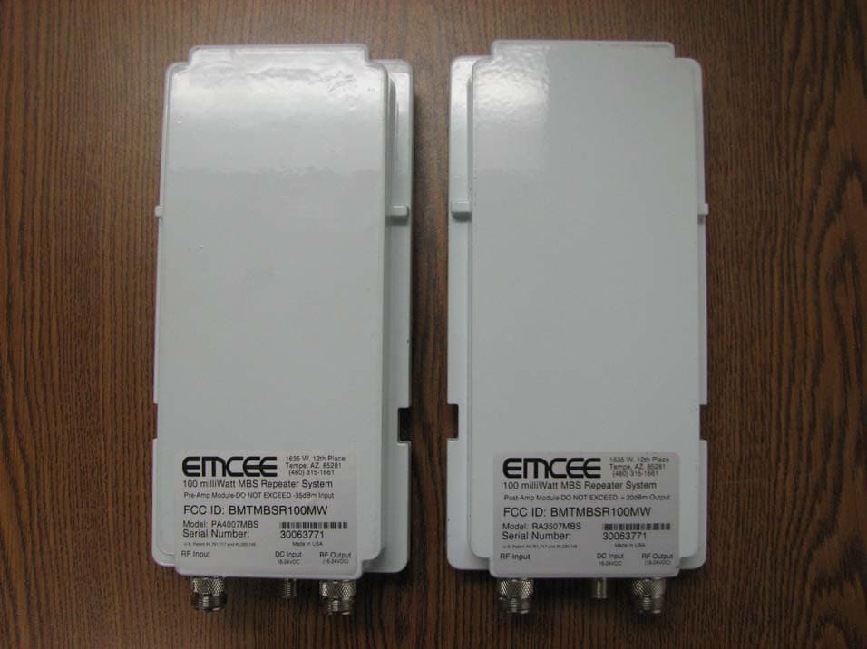
Click to zoom
Application Details
- Equipment Class
- TNB - Licensed Non-Broadcast Station Transmitter
- Date of Grant
- Aug 15, 2007
- Application Purpose
- Original Equipment
- Date of Application
- Jun 19, 2007
- Equipment Note
- Repeater
- Frequency Range
- 2572.00000000 - 2614.00000000
- Company
- EMCEE Broadcast Products
- Country
- United States
Documents & Files
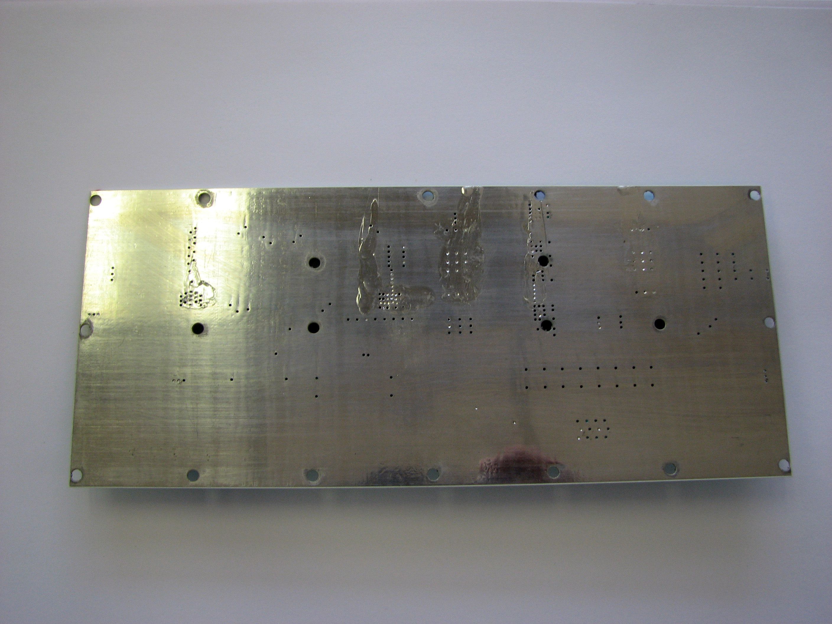
Document Text
Text extracted from the exhibit documents filed with the FCC. Open a document above to read the original.
Users Manual
Installation Instructions MBSR100MW MBS Repeater U.S Patent #4,791,717, #5,020,149 READ ME FIRST! The EMCEE MBSR100MW is a professional solid state low-power MBS Band retransmission repeater (amplifier) system, and is formed from a combination of a pre-selected frequency input pre-amplifier module (P/N 701007) and an AGC controlled 100mW post amplifier module (P/N 50800002A), each of which is in a separate chassis/housing and connected via an interconnecting coaxial cable with Type ‘N’ connectors. The system is capable of retransmitting from one to seven MBS channels with either analog NTSC or digital modulation. The system provides an end-to-end electrical gain typically 70dB. The system has no frequency generating circuits, and as such, the output carrier frequencies and modulations are dependent on the inputs. The pre-amplifier contains a dual section inter-digital filter system which provides high Q MBS pass-band circuitry at the input stage. This is to prevent pre-amplifier input overloads due to out of band interference from close stations utilizing the LBS and UBS bands. The input pre-selection also prevents the retransmission of out of band signals. The output (post) amplifier has an output AGC range of 20dB, with a 20dBm average power output power threshold. The AGC circuitry is designed to provide a constant low distortion output with varying input signal power levels due to fades and other signal anomalies. The system has the following average output power capability: 1 Channel @ 20dBm/Channel ±1dB (20dBm Composite Power) 2 Channels @ 17dBm/Channel ±1dB (20dBm Composite Power) 4 Channels @ 14dBm/Channel ±1dB (20dBm Composite Power) 7 Channels @ 11dBm/Channel ±1dB (20dBm Composite Power) Warning: DO NOT EXCEED 20dBm Composite Power Output! PLANNING the INSTALLATION Proper installation pre-planning will yield the best performance of the installed system. DANGER WATCH FOR WIRES You can be KILLED! If this product comes near electric power lines. EMCEE MBSR100MW Installation Instructions Page 2 DANGER WATCH FOR WIRES You can be KILLED! If this product comes near electric power lines. ©2007 EMCEE Communications Field deployment and configuration of the system includes fitting the system with the appropriate receive and re-transmit antennas. Typically, narrow beam parabolic reflectors are used to provide the necessary input/output link budget and output coverage area. The system, fully into the AGC range, has a maximum input power level of -35 dBm and is labeled “DO NOT EXCEED -35 dBm Input” accordingly. A typical installation will have input link characteristics as follows: Base Station EIRP (maximum) 60.0 dBm 10 Mile Path Loss -124.9 dB Receive Antenna Gain (typical) 24.0 dBi System Input Level - 40.9 dBm System Gain 70.0 dB Inter-Connecting Cable Loss -3.0 dB Transmit Antenna Gain (typical) 24.0 dBi EIRP 50.1 dBm Using a spectrum analyzer in the channel power mode, measure the RF output power level from the prospective receive antenna and confirm that the input power level is between -35 and -47dBm. If necessary, use a larger or smaller antenna to adjust the input level accordingly. As an alternate method, if the receive antenna output level is too high, a 50 Ohm, type ‘N’ attenuator may be used. Note: DO NOT use attenuators between the pre-amp and post-amp sections of the system. The repeater system has ~70dB of electrical gain plus the gain of the receive and transmit antennas. It is important that the transmit and receive antenna installation provides a high degree of isolation (at least 100dB) between them so the system does not oscillate due to feedback. This can be accomplished through vertical separation and cross-polarization of the antennas (50 feet recommended), providing input to output shielding by using building blockage or other means, while using good field engineering and installation practices. Install the pre-amplifier module as close as possible to the receive antenna to minimize the noise figure of the system. Also install the post-amp module as close as possible to the transmit antenna. Utilize a premium low-loss cable with quality connectors between the pre-amp and post-amp modules for the best performance results. EMCEE MBSR100MW Installation Instructions Page 3 DANGER WATCH FOR WIRES You can be KILLED! If this product comes near electric power lines. ©2007 EMCEE Communications Choose a transmit antenna that will provide the best coverage pattern for the shadowed area to be served. SERVICING the SYSTEM There are no internal user adjustments or user serviceable parts inside the unit. Do not disassemble the unit; the Warranty will be void if the unit is opened. If either module does not properly function, return it to the factory for repair or replacement. UNPACKING the SYSTEM Remove the power supply, then insert a finger into the finger hole of the inner carton liner, lift to expose unit and accessories. Remove the “L-Screw” from the mounting bracket and replace the bracket as shown. Install the power supply indoors close to an available AC outlet. Use a good quality RG-6 cable (min.) to connect the power supply between module power input and the power inserter. ATTACHING MODULES to the ANTENNA MAST Mount the modules with the connectors facing down. Slide the mounting clamp into the indentations on the housing and up into place. Hand-Tighten the “L-Screw” to secure the module to the antenna mast or tower leg. DO NOT use a wrench or pliers to tighten the “L-Screw”. Mast or tower leg size can be 1” to 2-1/2”. CONNECTING THE MODULES Connect the antenna output connector to the RF Input ‘N’ connector on the pre- amp module. Connect the RF inter-connecting cable ‘N’ connector to the ‘N’ jack marked RF output. Connect the RF inter-connecting cable ‘N’ connector to the RF input connector of the post-amp module. EMCEE MBSR100MW Installation Instructions Page 4 DANGER WATCH FOR WIRES You can be KILLED! If this product comes near electric power lines. ©2007 EMCEE Commun…
Text truncated - open the document above for the full version.
Attestation Statements
BMTMBSR100MW ATTESTATION STATEMENT I certify that the testing procedures and the accumulated test data contained in this report have been personally supervised by me, and that the test results are true and correct to the best of my knowledge and belief. ___________________ James A. Yard, CEO EMCEE Communications
Cover Letter(s)
1635 West 12 th Place Tempe, Arizona 85281 USA 480-315-1661 June 20, 2007 Joe Dichoso Office of Engineering and Technology Re: FCC ID BMTMBSR100MW Dear Sir: We formally request confidentiality for the schematic diagrams submitted with this application. These documents contain proprietary design specific information and are not released in the public domain. Sincerely, James A. Yard, CEO
External Photos
BMTMBSR100MW EXTERNAL PHOTOS
ID Label/Location Info
BMTMBSR100MW FCC IDENTIFICATION LABELS
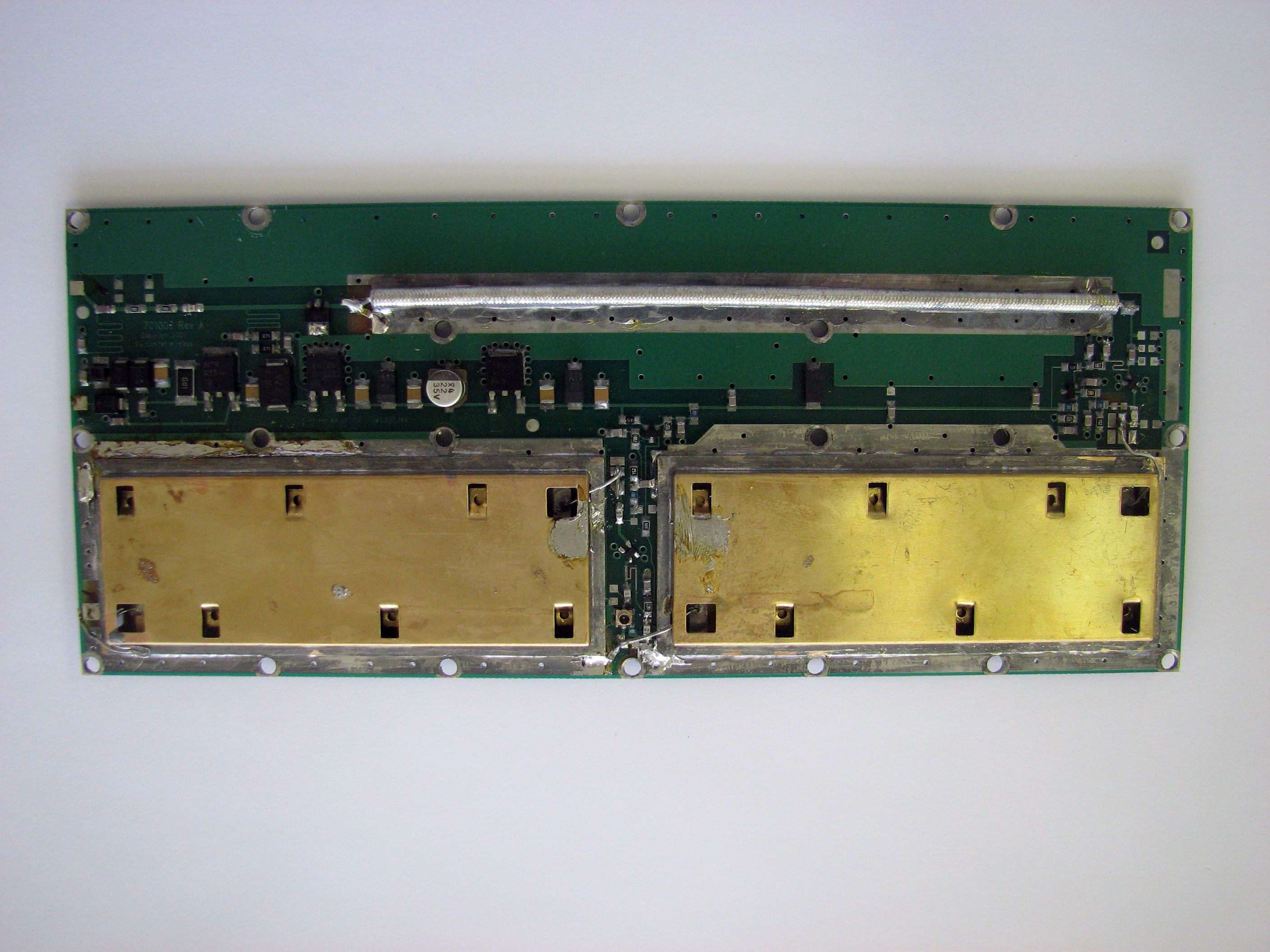
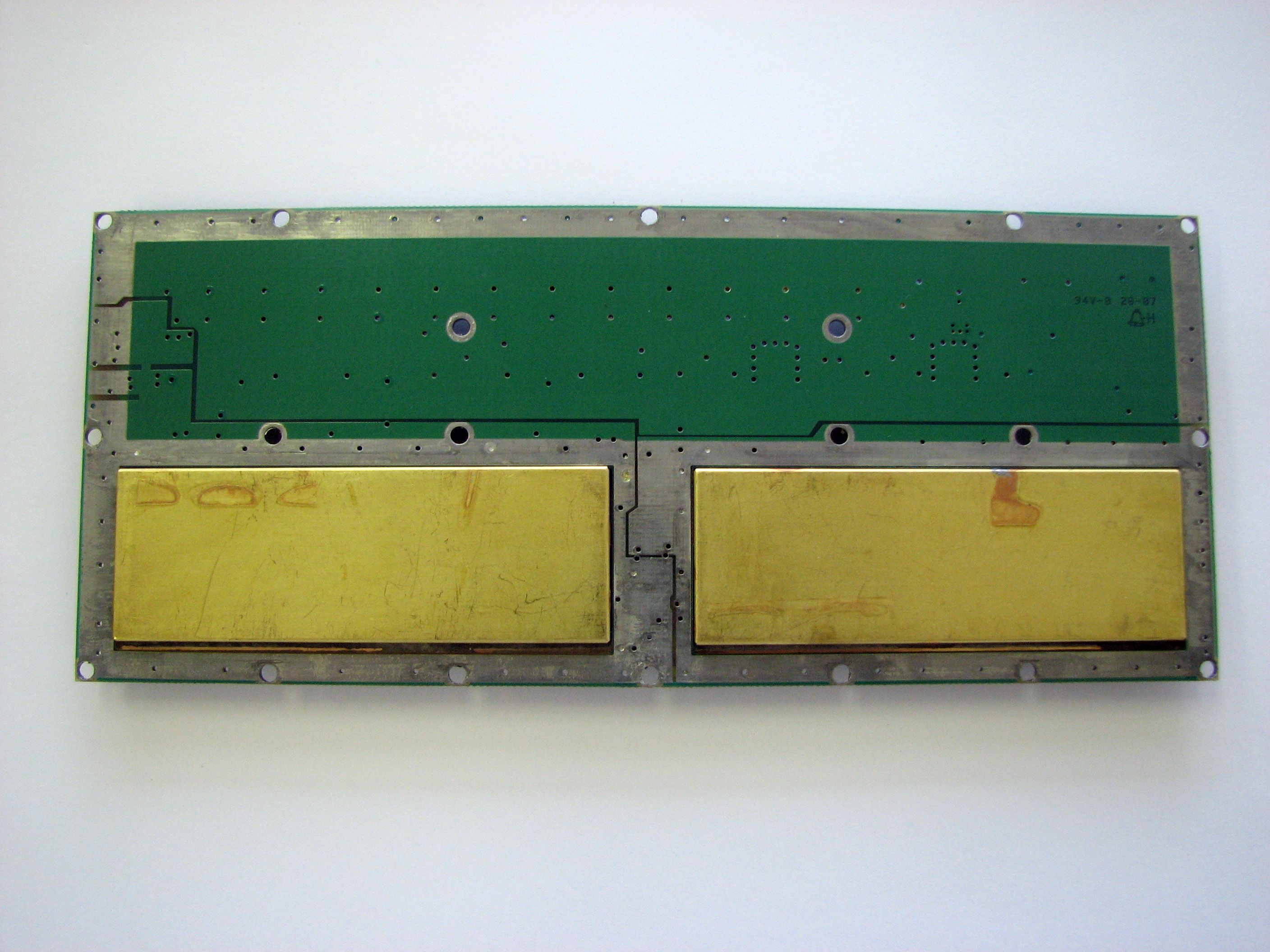
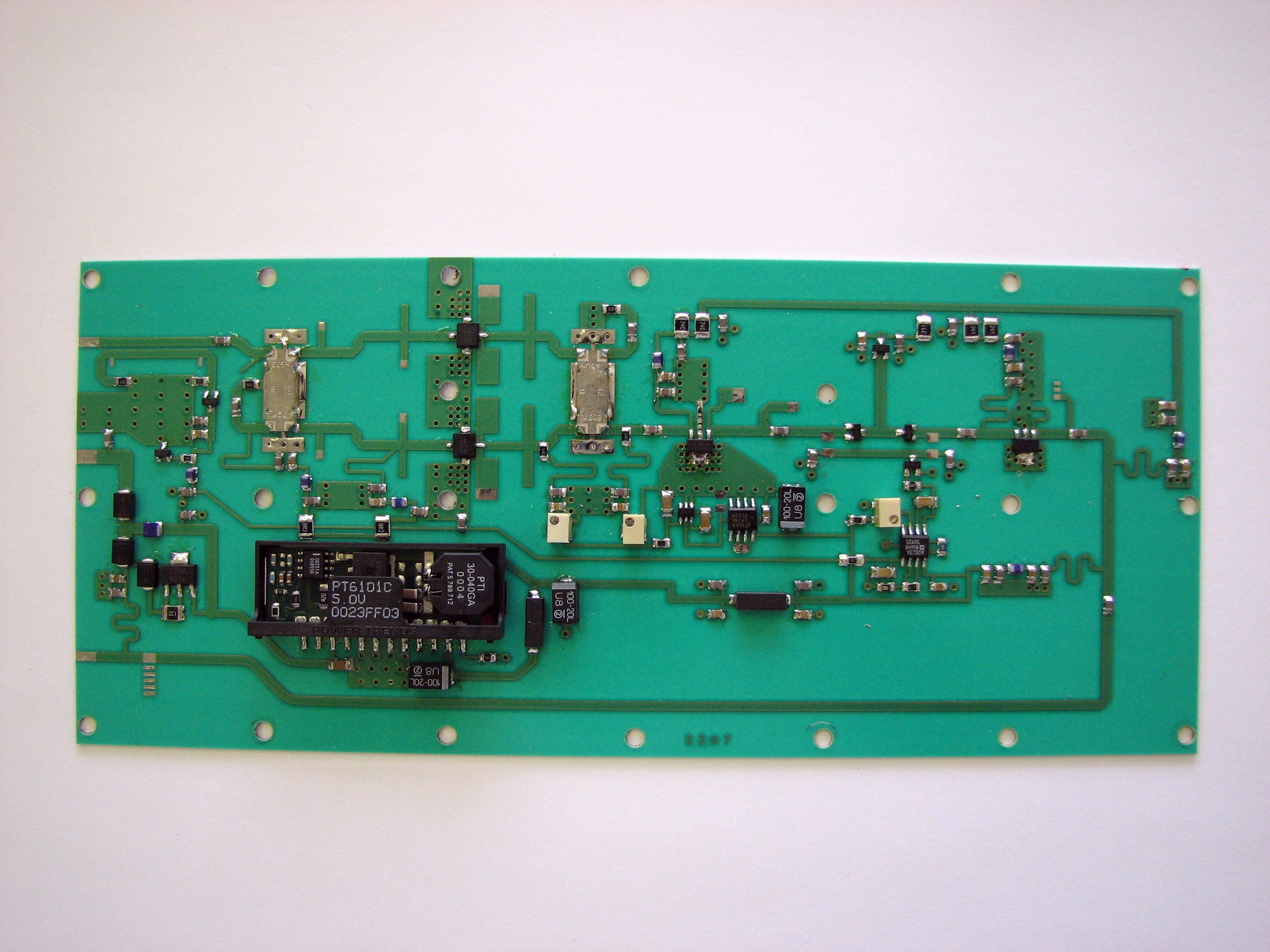
Internal Photos
BMTMBSR100MW INTERNAL PHOTO
Operational Description
BMTMBSR100MW OPERATIONAL DESCRIPTION The MBSR100MW is a solid state low-power MBS Band retransmission repeater (amplifier) system, and is formed from a combination of a pre-selected frequency input pre-amplifier module (P/N 701007) and an AGC controlled 100mW post amplifier module (P/N 50800002A), each of which is in a separate chassis/housing and connected via an interconnecting coaxial cable with Type ‘N’ connectors. The system is capable of retransmitting from one to seven MBS channels with either analog NTSC or digital modulation. The system provides an end-to-end gain of about 70dB. The system has no frequency generating circuits, and as such, the output carrier frequencies and modulations are dependent on the inputs. The pre-amplifier contains a dual section inter-digital filter system which provides high Q MBS pass-band circuitry at the input stage. This is to prevent pre-amplifier input overloads due to out of band interference from close stations utilizing the LBS and UBS bands. The input pre-selection also prevents the retransmission of out of band signals. The output (post) amplifier has an output AGC range of 20dB, with a 20dBm average power output power threshold. The AGC circuitry is necessary to provide a constant low distortion output with varying input signal power levels. Field deployment and configuration of the system includes fitting the system with the appropriate receive and re-transmit antennas. Typically, narrow beam parabolic reflectors are used to provide the necessary input/output link budget and output coverage area. The system, fully into the AGC range, has a maximum input level of -35 dBm and is labeled “DO NOT EXCEED -35 dBm Input” accordingly. A typical installation would have input link characteristics as follows: Base Station EIRP (maximum) 63.0 dBm 10 Mile Path Loss -124.9 dB Receive Antenna Gain (typical) 24.0 dB System Input Level - 37.9 dBm The spectral performance of the system complies with FCC §27.53. All construction and manufacturing techniques are in accordance with accepted principles of good engineering and manufacturing practice. The system is powered with a low voltage (16-24VDC) supply and requires low current (<1 Ampere), and as such, no hazard to operating personnel exists. The pre-amp and post amplifier modules are sealed, therefore there are no user serviceable parts or adjustments inside.
Test Report
FCC TYPE ACCEPTANCE REPORT FOR THE BMTMBSR100MW, 100 mW MBS BAND BOOSTER SYSTEM EMCEE Communications 1635 West 12 th Place Tempe, AZ 85281 480-315-1661 Application For FCC Certification MBSR100MW-Test Report Page 2 TABLE OF CONTENTS 1.0 INTRODUCTION.....................................................................................................3 2.0 CERTIFICATION OF DATA ......................................................................................3 4.0 OPERATIONAL DESCRIPTION ................................................................................4 4.1 SYSTEM SPECIFICATIONS........................................................................................... 5 5.0 EXTERNAL PHOTOS...............................................................................................5 5.1 IDENTIFICATION LABEL.............................................................................................. 6 6.0 INTERNAL PHOTOS ...............................................................................................6 7.0 PARTS LISTS AND TUNE-UP PROCEEDURE ...........................................................7 8.0 TEST RESULTS ......................................................................................................9 8.1 SYSTEM GAIN MEASUREMENT............................................................................. 9 8.2 OCCUPIED BANDWIDTH ...................................................................................... 9 8.3 POWER OUTPUT MEASUREMENTS .................................................................... 11 8.4 SPURIOUS EMISSIONS AT ANTENNA TERMINALS.............................................. 13 8.5 ATTENUATION CHARACTERISTICS & FREQUENCY RESPONSE ......................... 18 8.6 MODULATION CHARACTERISTICS..................................................................... 20 8.7 FREQUENCY STABILITY ..................................................................................... 20 8.8 FIELD STRENGTH OF SPURIOUS EMISSIONS ..................................................... 21 9.0 SUMMARY ...........................................................................................................22 Application For FCC Certification MBSR100MW-Test Report Page 3 1.0 INTRODUCTION This report contains the required information for type acceptance of the EMCEE Model MBSR100MW low-power repeater system. The data presented was taken from laboratory tests performed on a production repeater system designed to receive and amplify up to seven digital or analog channels in the MBS band (2572-2614 MHz). This device is intended to provide retransmission gap filling into service areas which are shadowed from reception from the main MBS base station. The repeater system design and test data reflect the rules as prescribed in Part 27 of the Commission’s Rules. 2.0 CERTIFICATION OF DATA FCC §2.909 I certify that the testing procedures and the accumulated test data contained in this report have been personally supervised by me, and that the test results are true and correct to the best of my knowledge and belief. ___________________ James A. Yard, CEO EMCEE Communications 3.0 TEST EQUIPMENT The following is a list of major test equipment which was used in testing the PA-2507MBS and RA-2507MBS low power repeater system. Manufacturer Model # Serial Number Description HP/Agilent 89431A US39312280 VSA RF Section HP/Agilent 89441A US39313875 Vector Signal Analyzer HP/Agilent 8753ES US39171643 Vector Network Analyzer HP/Agilent E4433B US38080113 Signal Generator (2) HP/Agilent E4402B US39010125 Spectrum Analyzer HP/Agilent E3611 KR83015731 DC Power Supply HP/Agilent E7405A US39440172 EMC/Spectrum Analyzer Conifer MC-7EBS Multi-channel Analog/Digital Signal Source Application For FCC Certification MBSR100MW-Test Report Page 4 4.0 OPERATIONAL DESCRIPTION The MBSR100MW is a solid state low-power MBS Band retransmission repeater (amplifier) system, and is formed from a combination of a pre-selected frequency input pre-amplifier module (P/N 701007) and an AGC controlled 100mW post amplifier module (P/N 50800002A), each of which is in a separate chassis/housing and connected via an interconnecting coaxial cable with Type ‘N’ connectors. The system is capable of retransmitting from one to seven MBS channels with either analog NTSC or digital modulation. The system provides an end-to-end gain of about 70dB. The system has no frequency generating circuits, and as such, the output carrier frequencies and modulations are dependent on the inputs. The pre-amplifier contains a dual section inter-digital filter system which provides high Q MBS pass-band circuitry at the input stage. This is to prevent pre-amplifier input overloads due to out of band interference from close stations utilizing the LBS and UBS bands. The input pre-selection also prevents the retransmission of out of band signals. The output (post) amplifier has an output AGC range of 20dB, with a 20dBm average power output power threshold. The AGC circuitry is necessary to provide a constant low distortion output with varying input signal power levels. Field deployment and configuration of the system includes fitting the system with the appropriate receive and re-transmit antennas. Typically, narrow beam parabolic reflectors are used to provide the necessary input/output link budget and output coverage area. The system, fully into the AGC range, has a maximum input level of -35 dBm and is labeled “DO NOT EXCEED -35 dBm Input” accordingly. A typical installation would have input link characteristics as follows: Base Station EIRP (maximum) 63.0 dBm 10 Mile Path Loss -124.9 dB Receive Antenna Gain (typical) 24.0 dB System Input Level - 37.9 dBm The spectral performance of the system complies with FCC §27.53. All construction and manufacturing techniques are in accordance with accepted principles of good engineering and manufacturing practice. The system is powered with a low voltage (16-24VDC) supply a…
Text truncated - open the document above for the full version.
Test Setup Photos
BMTMBSR100MW TEST SETUP PHOTO
Contact Information
Applicant
James A Yard(CEO)
Technical Specifications
| # | Rule Parts | Frequency Range | Power Output | Emission | Tolerance |
|---|---|---|---|---|---|
| 1 | 27 | 2.57 GHz - 2.61 GHz | 100.00 mW | D7W | Amp |
Other Applications from EMCEE Broadcast Products
BMTLPU500
Sep 22, 2009Broadcast Transmitter
Equipment Class
TBC - Licensed Broadcast Station Transmitter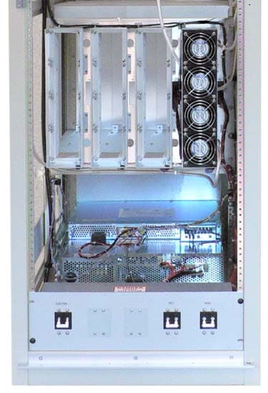
BMTTTHDU250
Aug 17, 2009Broadcast Transmitter
Equipment Class
TBC - Licensed Broadcast Station Transmitter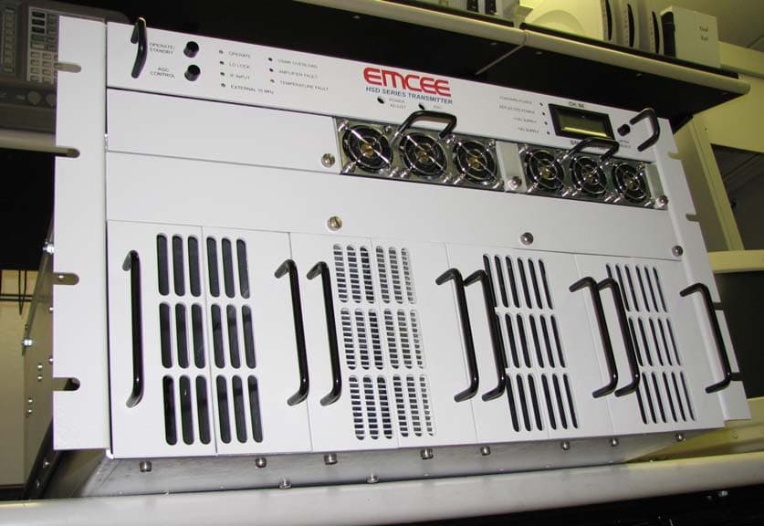
BMTHSD-1250
Jan 22, 2008EBS/BRS Transmitter
Equipment Class
TNB - Licensed Non-Broadcast Station Transmitter
BMTHSD-2500
Nov 25, 2007Transmitter
Equipment Class
TNB - Licensed Non-Broadcast Station Transmitter
BMTHSD-5000
Oct 22, 2007MMDS/ITFS/EBS/BRS Transmitter
Equipment Class
TNB - Licensed Non-Broadcast Station Transmitter