BOILAXTMaxiva LAXT Digital Television Transmitter
GatesAir, Inc.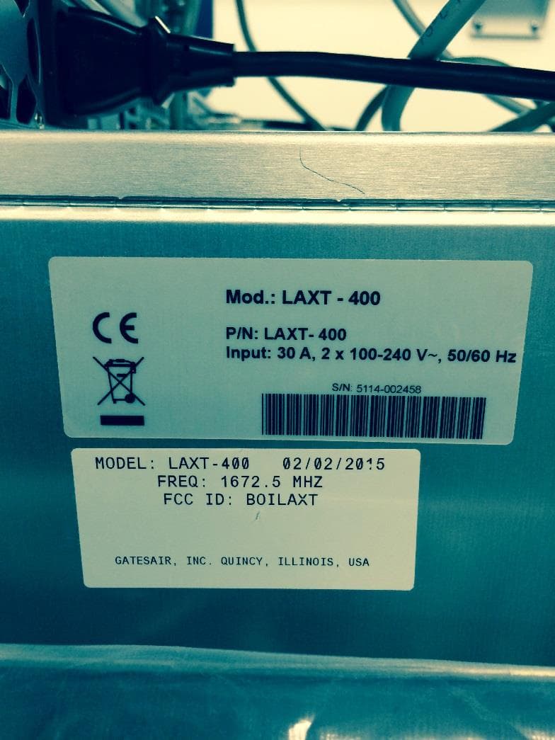
Click to zoom
Application Details
- Equipment Class
- TNB - Licensed Non-Broadcast Station Transmitter
- Date of Grant
- Apr 23, 2015
- Application Purpose
- Original Equipment
- Date of Application
- Feb 08, 2015
- Equipment Note
- Maxiva LAXT Digital Television Transmitter
- Frequency Range
- 1672.50000000 - 1672.50000000
- Company
- GatesAir, Inc.
- Country
- United States
Documents & Files
Document Text
Text extracted from the exhibit documents filed with the FCC. Open a document above to read the original.
Cover Letter(s)
5300 Kings Island Dr Mason, OH USA 45040 1 800.622.0022 gatesair.com Application for Equipment Certification Feb 07, 2015 To Whom it may Concern, This letter and the accompanying test report and documents are in application for FCC Certification of a series of Digital Television transmitters to be operated under the requirements of FCC Part 27.53 (j). Four models of the Maxiva LAXT series of transmitters are included in this application, with power output ratings from 50 watts to 400 watts, before the output filter. All models use identical sub-assemblies, with the only significant difference between them being that the 400W system uses a combiner and the other system could have single or dual outputs to achieve the desired power levels. The other significant difference being the number of output amplifier modules used to produce the required power. The Maxiva LAXT series of transmitters are an advanced modular design, using the same components and assemblies in a building-block approach to create transmitters with output power ratings from 50 watts to 400 watts at the output connection or connections. A single transmitter houses each model. Our test report intends to show that the performance of the transmitter is well within the limits imposed by Part 27.53 (j). Tests were conducted on a single 400 watt model, the LAXT-400. This is the highest output power level offered in this series of transmitters. These tests are also asserted to be typical of the performance to be had from lower power versions of the same transmitter.
Cover Letter(s)
5300 Kings Island Dr Mason, OH USA 45040 1 800.622.0022 gatesair.com Application for Equipment Certification TABLE OF CONTENTS Confidentiality Requested 1. Cover Letter NO 2. Table of Contents NO 3. Request for Confidentiality NO A. Equipment ID Label Plate and Mounting Location NO B. Modulation Description NO C. Technical Description YES D. Installation and Operating Instructions/Technical Manual YES E. Tuning Up Procedure YES F. Schematics YES G. Modulator Schematic YES H. LAXT-400 Transmitter Photos YES I. PA Module Description YES J. DC Voltages and Currents of Final Amplifiers NO K. PA Module Photos YES L. Output Bandpass Filter Specification YES M. Test Report NO
Cover Letter(s)
5300 Kings Island Dr Mason, OH USA 45040 1 800.622.0022 gatesair.com NDA Example RESTRICTED ACCESS OF EQUIPMENT AND DOCUMENTATION NOTICE This Restricted Access of Equipment and Documentation Notice is to inform (insert name of FCC licensee) that access to equipment and related documentation supplied by GatesAir, Inc. is to be restricted to only authorized users by means to ensure the security of the equipment and confidentiality of related documentation at all times, and only designated professionals shall be allowed to maintain or service the equipment. This notice includes, but is not limited to, internal photographs and user manuals to be held confidential and out of the public domain. GatesAir, Inc. By: Name: John Harmon Title: Compliance Engineer Date: Jan 30, 2015 Place: Mason, OH
Cover Letter(s)
5300 Kings Island Dr Mason, OH USA 45040 1 800.622.0022 gatesair.com Feb 18, 2015 To: Evelyn Cherry Re: FCC Correspondence Number: 46703 Dear Ms. Cherry, In response to your email – correspondence number: 46703, “... Below is the updated filing request plus the document specifically states that: “...the Exhibits marked on the Table of Contents "Confidentiality Requested", and also marked as "Confidential" on their cover pages, be withheld from public inspection.” And also “To support the requested confidentiality, we have placed the information requested to be kept confidential in Exhibits whose cover pages and whose entries in the Table of Contents are marked as described above. The table of contents page states each exhibit specifically its status.” The amended document below is signed and dated and does now reference both FCC rules. Best Regards, John Harmon 5300 Kings Island Dr Mason, OH USA 45040 1 800.622.0022 gatesair.com Feb 09, 2015 Request for Confidentiality Pursuant to 47CFR 0.459 and 0.457(d), we hereby request that the Exhibits marked on the Table of Contents "Confidentiality Requested", and also marked as "Confidential" on their cover pages, be withheld from public inspection. Each Exhibit so-marked contains information of a proprietary nature to our company, and possibly to our customers also. Information which could be obtained from the cited Exhibits, which are commonly known as "Trade Secrets", includes printed circuit trace routing, component selection, RF circuit "broadbanding" techniques, mechanical construction layouts and modulation methods. The confidentiality of such information is carefully guarded within our company, and only shared when further disclosure is restricted by binding agreement. Additional proprietary information is contained within drawings, schematics and equipment configuration instructions, normally supplied to customers only after their purchase of the described equipment. Our customers, after having made such purchases, have no reason to share the documents with other parties and, in some cases, may be restricted from doing so by binding agreement. Additionally, those documents are normally supplied as hard copies as part of the equipment's documentation, and often in a size that is difficult to duplicate with standard office equipment. We are therefore concerned that in the event the above described information were to be made available in a public forum, particularly one as easy to access as the World Wide Web, our competitors, or those of our customers, could easily obtain and use it to compromise our ability, and that of our customers, to maintain our respective competitive positions in the marketplace worldwide. We therefore respectfully ask that you honor our request to maintain that confidentiality in regard to the selected documents. To support the requested confidentiality, we have placed the information requested to be kept confidential in Exhibits whose cover pages and whose entries in the Table of Contents are marked as described above. Sincerely, John Harmon Compliance Engineer 513.459.3804 (office) [email protected]
Cover Letter(s)
5300 Kings Island Dr Mason, OH USA 45040 1 800.622.0022 gatesair.com Grant Status Notification BOILAXT Apr 14, 2015 To Whom it may Concern, I was inquiring on the status of the application for FCC ID: BOILAXT, Confirmation number EA885711. Thank you for reply, Best Regards, John Harmon
Cover Letter(s)
5300 Kings Island Dr Mason, OH USA 45040 1 800.622.0022 gatesair.com Application for Equipment Certification TABLE OF CONTENTS Confidentiality Requested 1. Cover Letter NO 2. Table of Contents NO 3. Request for Confidentiality NO A. Equipment ID Label Plate and Mounting Location NO B. Modulation Description NO C. Technical Description YES D. Installation and Operating Instructions/Technical Manual YES E. Tuning Up Procedure YES F. Schematics YES G. Modulator Schematic YES H. LAXT-400 Transmitter Photos NO I. PA Module Description YES J. DC Voltages and Currents of Final Amplifiers NO K. PA Module Photos YES L. Output Bandpass Filter Specification YES M. Test Report NO
Cover Letter(s)
5300 Kings Island Dr Mason, OH USA 45040 1 800.622.0022 gatesair.com April 24, 2015 To: Evelyn Prado Re: FCC Correspondence Number: 46771 Dear Ms. Prado, In response to your email – correspondence number: 46703, The Table of Contents has been updated to reflect that the LAXT-400 Transmitters external photos (Exhibit H) are not confidential. The amended document has been submitted along with this document. Best Regards, John Harmon
External Photos
5300 Kings Island Dr Mason, OH USA 45040 1 800.622.0022 gatesair.com Application for Equipment Certification EXHIBIT A ID Label Plate and Location 2.1033 (c) (11) Identification Plate A photograph or drawing of the equipment identification plate or label showing the information to be placed thereon.
External Photos
5300 Kings Island Dr Mason, OH USA 45040 1 800.622.0022 gatesair.com Application for Equipment Certification EXHIBIT H Transmitter Photos Front View Rear View Side Side Bottom
ID Label/Location Info
5300 Kings Island Dr Mason, OH USA 45040 1 800.622.0022 gatesair.com Application for Equipment Certification EXHIBIT A ID Label Plate and Location 2.1033 (c) (11) Identification Plate A photograph or drawing of the equipment identification plate or label showing the information to be placed thereon.
Operational Description
5300 Kings Island Dr Mason, OH USA 45040 1 800.622.0022 gatesair.com EXHIBIT B Modulation Description The type of modulation used in the Maxiva LAXT transmitters is DVB-H. This is a COFDM modulation transmission standard. It is fully described in ETSI standard EN 300 744. The particular form of DVB-H transmission intended for this particular use with a channel width of 5 MHz.
Operational Description
5300 Kings Island Dr Mason, OH USA 45040 1 800.622.0022 gatesair.com Application for Equipment Certification EXHIBIT J DC Voltages and Currents of Final Amplifier 2.1033 (c) (8) Final amplifier DC voltages & currents The LAXT has two main power supplies that provide voltages for the transmitter system, 28 VDC and 50 VDC. The 28 VDC is used to power the control circuitry while the 50 VDC is used to power the RF Power circuits. The 50 VDC outputs from each supply are diode OR’d together on the Motherboard. If one power supply fails the transmitter will operate a reduced power of -6 dB. A display screen from the transmitter has been captured to show the required data.
RF Exposure Info
5300 Kings Island Dr Mason, OH USA 45040 1 800.622.0022 gatesair.com RF Exposure The antenna(s) used for this transmitter must be fixed-mounted on outdoor permanent structures. RF exposure compliance is addressed at the time of licensing, as required by the responsible FCC Bureau(s), including antenna co- location requirements of section 1.1307(b)(3).
Test Report
Page 1 of 34 Certification of Compliance Maxiva LAXT Digital TV Transmitter for FCC Title 47 This document is compiled to provide the data and records supporting a Certification of Compliance with FCC Rules set forth in 47CFR Parts 2 and 27. Certification as described in Part 2, Subpart J applies to all subsequent identical units marketed. Use of the Certification method requires that the required records are filed accompanying FCC Form 731. The test record shall be retained as required by 2.938(c). The transmitter tested is referred to by GatesAir as: Trade Name MAXIVA LAXT FCC Identifier BOILAXT Frequency 1672.5 MHz Model: Rated Power LAXT-50 50 Watts LAXT-100 100 Watts LAXT-200 200 Watts LAXT-400(Tested) 400 Watts Sample Tested: LAXT-400 400 Watts Serial Number 5114-002576 The person responsible for testing is: ________________________________________ John Harmon 02-08-2014 Compliance Engineer Page 2 of 34 Table of Contents As an aid to locating needed information in this document, the following Table of Contents links each portion of the record with the appropriate Rule and locates it in this document by page number. Rule # Page Rules and Standards Applied in these Measurements ................................................................................... 3 Test Equipment Used in these Measurements .............................................................................................. 3 2.938 Retention of records. .................................................................................................................. 4 (a) Records to be maintained ........................................................................................................... 4 (1) Original Design Drawings and Specifications ............................................................................. 4 (2) Production Testing and Inspection Procedures ......................................................................... 4 (3) Test Results Demonstrating Compliance ................................................................................... 4 (c) Record retention period ............................................................................................................. 4 2.1033 Application for certification. ....................................................................................................... 5 (a) Filed on FCC Form 731 ................................................................................................................ 5 (c) Contents of Technical Report ..................................................................................................... 5 (1) Name and address of manufacturer .......................................................................................... 5 (2) FCC Identifier ............................................................................................................................. 5 (3) Installation and operating instructions ...................................................................................... 5 (4) Type or Types of emission, ........................................................................................................ 5 (5) Frequency Range ....................................................................................................................... 5 (6) Range of operating power ......................................................................................................... 6 (7) Maximum Power ....................................................................................................................... 6 (8) Final amplifier DC voltages & currents ...................................................................................... 6 (9) Tune-up procedure .................................................................................................................... 7 (10) Schematics & Circuit descriptions.............................................................................................. 7 (11) Identification Plate .................................................................................................................... 7 (12) Photographs of equipment ........................................................................................................ 8 (13) Description of digital modulation ............................................................................................ 15 (14) Required Data, 2.1046 through 2.1057 ................................................................................... 15 2.1046 Measurements required: RF power output. ............................................................................. 16 27.53 Emission limits. ............................................................................................................................. 17 2.1047 Measurements required: Modulation characteristics. ............................................................. 18 2.1057 Frequency spectrum to be investigated. .................................................................................. 21 2.1051 Measurements required: Spurious emissions at antenna terminals. ....................................... 24 2.1053 Measurements required: Field strength of spurious radiation. ............................................... 27 2.1055 Measurements required: Frequency stability. ......................................................................... 33 Page 3 of 34 Rules and Standards Applied in these Measurements Requirement: Standard / Procedure 2.1046(a), (c)RF Power Output The output power at the transmitter output flange and at the output from the output bandpass filter were both measured while operating into a standard test load, using a calibrated RF power meter. 2.1047 27.53(j) Emission Limits Adjacent Bands Measured and calculated as directed by 27.53(j). Output power from the bandpass filter was used as the reference output power for measurement of out of band em…
Text truncated - open the document above for the full version.
Contact Information
Applicant
John R Harmon(Compliance Engineer)
Technical Contact
GatesAir, Inc.John Harmon
[email protected]5134593804
5300 Kings Island Dr Ste 101 · Mason, Ohio · United States
Non-Technical Contact
GatesAir, IncRay Miklius
[email protected]5134593495
Technical Specifications
| # | Rule Parts | Frequency Range | Power Output | Emission | Tolerance |
|---|---|---|---|---|---|
| 4 | 27 | 1.67 GHz - 1.67 GHz | 50 W | 5M00W7W | 2 Hz |
Other Applications from GatesAir, Inc.
BOI-GXLP300
Dec 04, 2024LPFM Transmitter
Equipment Class
TBC - Licensed Broadcast Station Transmitter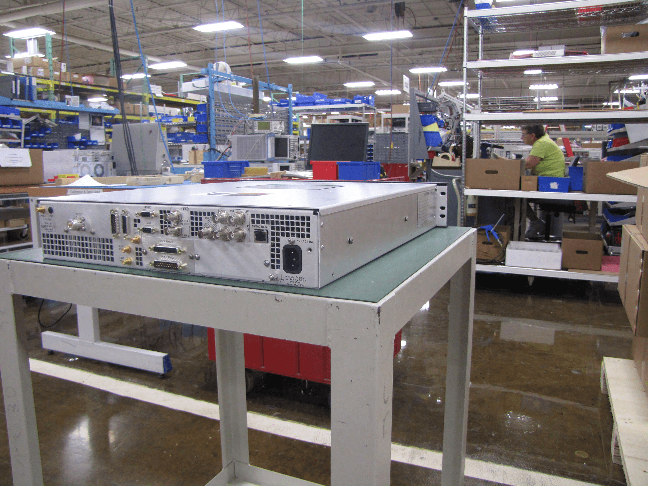
BOIUAXCC
Mar 24, 2014Maxiva Compact Class
Equipment Class
TBC - Licensed Broadcast Station Transmitter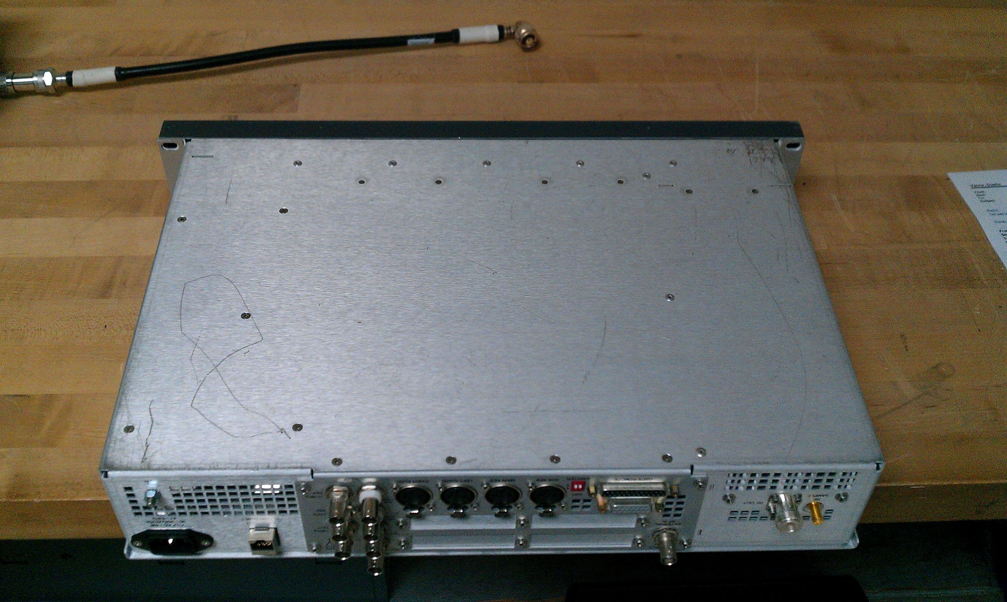
BOIFAXLP
Feb 04, 2014Flexiva Air-Cooled FM Transmitter/Exciter for Analog and Digital Standards Compact Class, Low Power - 50 W to 3.5 kW
Equipment Class
TBC - Licensed Broadcast Station Transmitter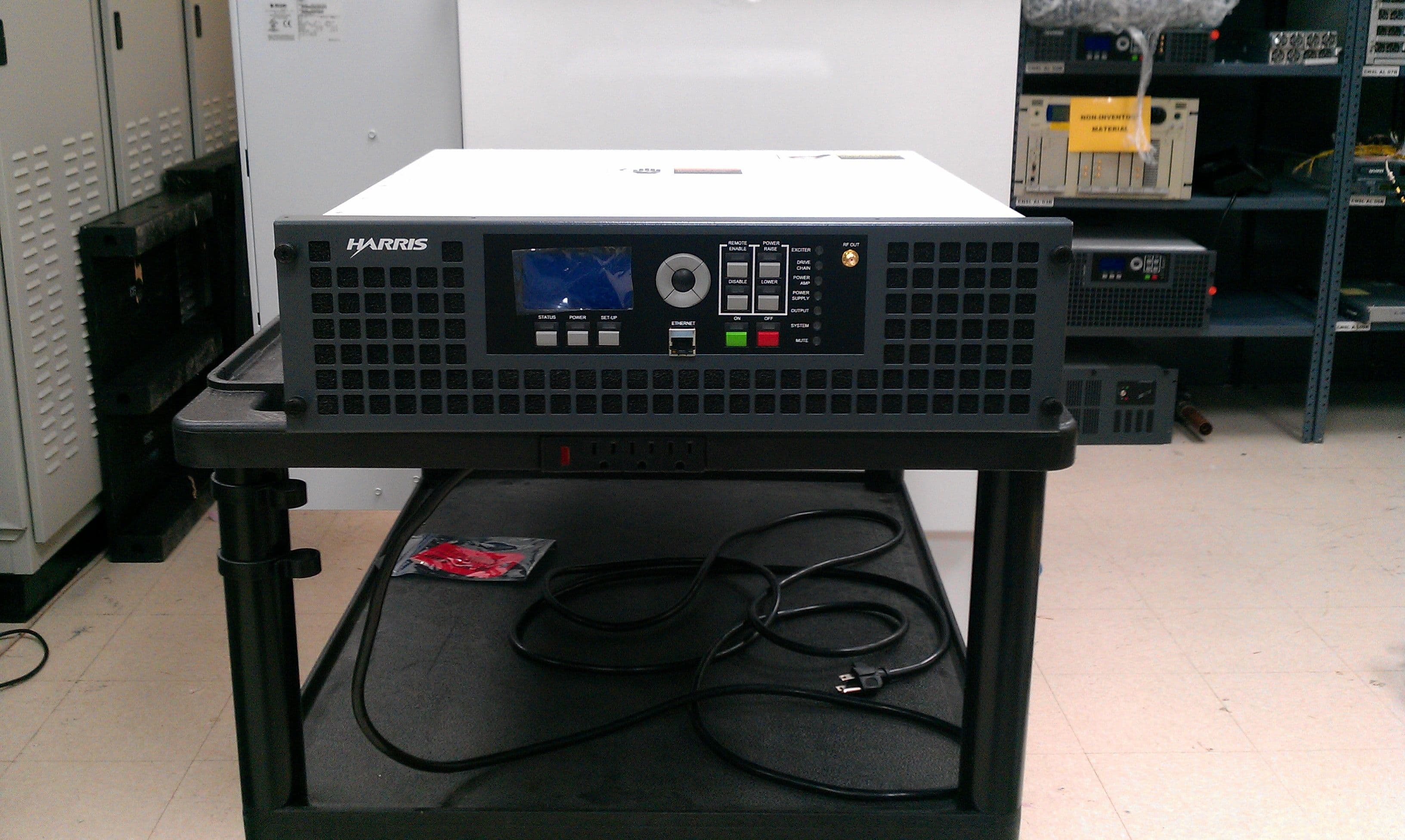
BOIFAXMP
Feb 03, 2014Air-Cooled FM Transmitter for Analog and Digital Standards Compact Class, Low Power
Equipment Class
TBC - Licensed Broadcast Station Transmitter
BOI-UAXFLID
Oct 25, 2010Maxiva UAX Transmitter Indoor System
Equipment Class
TNB - Licensed Non-Broadcast Station Transmitter