BOIUAXCCMaxiva Compact Class
GatesAir, Inc.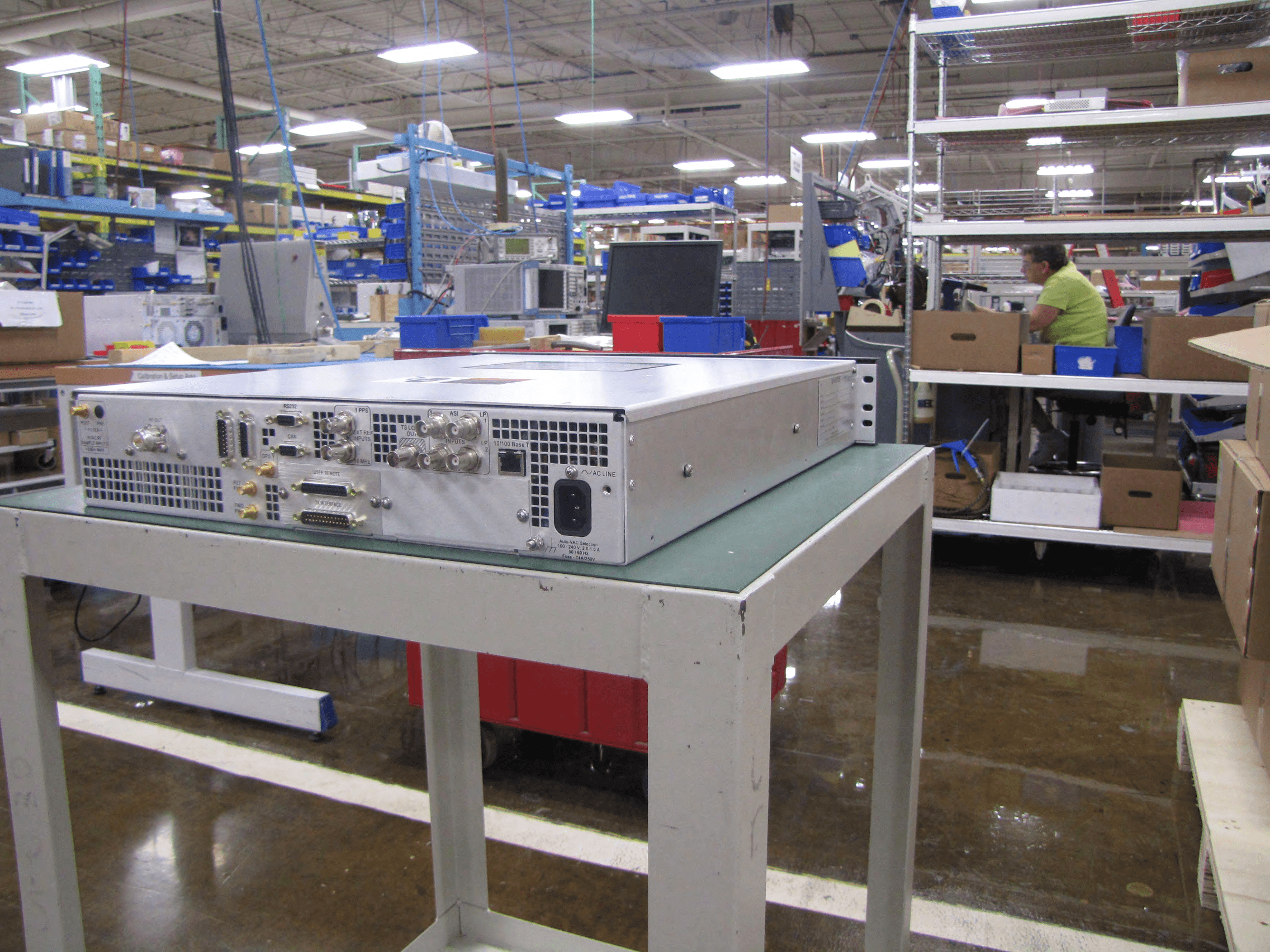
Click to zoom
Application Details
- Equipment Class
- TBC - Licensed Broadcast Station Transmitter
- Date of Grant
- Mar 24, 2014
- Application Purpose
- Original Equipment
- Date of Application
- Nov 04, 2013
- Equipment Note
- Maxiva Compact Class
- Frequency Range
- 614.00000000 - 806.00000000
- Company
- GatesAir, Inc.
- Country
- United States
Documents & Files
Document Text
Text extracted from the exhibit documents filed with the FCC. Open a document above to read the original.
Attestation Statements
Harris Oct 1 To W In re g No ch Since John Carl W Broadcast is an ind 7, 2013 hom it May C o gards to the M hanges have be rely, Harmon Williams dependent compan oncern: axiva Compac t een made to th ny not affiliated with t Class Transm he design or m h Harris Corporation itter, FCC ID: B anufacture sin n. BOIUAXCC: nce the testing date of Augu sst 23 – Septem 9800 South Meridi Eng ber 10, 2011 . ian Boulevard, Suite 30 glewood, CO USA 801 phone 1‐303‐476‐50 0 harrisbroadcast.co 00 12 00 om
Cover Letter(s)
22 April 2013 Nemko Canada Inc 303 River Road Ottawa, Ontario, Canada K1V 1H2 Attn: Director of Certification Authority to Act as Agent FCC On our behalf, I appoint Jenny Gibbs of Nemko USA, Inc. at 802 N Kealy Avenue, Lewisville TX 75057 to act as our agent in the preparation of this application for equipment certification. I certify that submitted documents properly describe the device or system for which equipment certification is sought. I also certify that each unit manufactured, imported or marketed, as defined in FCC regulations will have affixed to it a label identical to that submitted for approval with this application. In signing this letter, Applicant certifies that neither the applicant nor any party to the application is not subject to a denial of Federal benefits, that include FCC benefits, pursuant to Section 5301 of the Anti-Drug Abuse Act of 1988, 21 U.S.C. § 862 because of a conviction for possession or distribution of a controlled substance. See 47 CFR 1.2002(b) for the definition of a "party" for these purposes. For instances where our authorized agent signs the application for certification on our behalf, I acknowledge that all responsibility for complying with the terms and conditions for certification, as specified by Nemko Canada Inc, still resides at Harris Broadcast, 3200 Wismann Ln, Quincy, IL 62301. Dated this 22 Day of April 20 13 Agency agreement expiration date: 22 April 2014 By: Carl B Williams Signature Printed Title: Systems engineer On behalf of : HarrisBroadcast Telephone: 217-221-7334
Cover Letter(s)
Carl Williams P.O. Box 4290 Quincy, IL 62301 217.221.7334 22 April 2013 Nemko Canada Inc. 303 River Road Ottawa, Ontario, Canada K1V 1H2 FCC ID: BOIUAXCC Product Name: Maxiva Compact Class Request for Confidentiality Pursuant to Sections 0.457 and 0.459 of the commission’s rules, we hereby request that the following documents be held confidential: • Schematics • Block diagram • Bill of Materials/Parts List • Technical/Operational Description • User Manual • Internal Photos These materials contain trade secrets and proprietary information and are not customarily released to the public. The public disclosure of this information might be harmful to the company and provide unjustified benefits to our competitors. In addition, we hereby provide additional justification to request the user manual and internal photos provided, as held under long-term confidenitiality in accordance with FCC rules for this non-consumer device. These exhibits are for licensed professional use only and not made for public use. These exhibits are kept in secured file at Harris facility for licensed operators only designated by Harris. NDA process is used to control non-authorized use of the manual. Dated this 22 Day of April 20 13 By: Carl B Williams Signature Printed Title: Systems Engineer On behalf of : HarrisBroadcast Telephone: 217-221-7334
Cover Letter(s)
RESTRICTED ACCESS OF EQUIPMENT AND DOCUMENTATION NOTICE This Restricted Access of Equipment and Documentation Notice is to inform (insert name of FCC licensee) that access to equipment and related documentation supplied by HBC Solutions, Inc. is to be restricted to only authorized users by means to ensure the security of the equipment and confidentiality of related documentation at all times, and only designated professionals shall be allowed to maintain or service the equipment. This notice includes, but is not limited to, internal photographs and user manuals to be held confidential and out of the public domain. HBC Solutions, Inc. By: ______________ Name: _Carl Williams_________________________ Title: ____System Engineer____________________ Date: ______April 23, 2012________ ____________ Place: ____Quincy, IL____ _____________________
ID Label/Location Info
MODEL: UAX-80AT-C DATE: 4/4/2013 PART NO: 995-0318-001G FCC ID: BOIUAXCC SERIAL NO: KH10003264-1-09 OTHER ID: FREQUENCY: 683 MHZ CHANNEL: 49 POWER OUT: .100 KW AVG PK 100-240 VAC 1 PHASE 50/60 HZ WORK ORDER#: PRD0441278 OPERATION#: 10 Use small plate
Parts List/Tune Up Info
11/27/12888-2843-0015-1 WARNING: Disconnect primary power prior to servicing. Maxiva UAX-C Series Section 5 Maintenance and Alignments 5 This section contains the maintenance and alignment procedures for the Maxiva UAX- C Series UHF transmitter. This includes routine maintenance, PA module replacement, PA module repair, transmitter calibration and PC Board replacement procedures. ! WA R N I N G : THE SERVICE WORK DESCRIBED IN THIS SECTION MUST BE CARRIED OUT BY TRAINED STAFF ONLY. 5.1Technical Assistance Refer to the page iii at the front of the manual for further information regarding technical assistance. 5-2888-2843-00111/27/12 WARNING: Disconnect primary power prior to servicing. Section 5 Maintenance and Alignments Maxiva UAX-C Series 5.2PA Module Removal and Replacement ! CAUTION: TOXIC BERYLLIUM SOME COMPONENTS IN THE PA MODULE CONTAIN TOXIC BERYLLIUM. THIS LIMITS MODULE REPAIR TO A MODULAR LEVEL CONSISTING OF PALLETS AND PC BOARDS ONLY. HOT SURFACE MAXIVA PA MODULES ARE DESIGNED TO HANDLE VERY HIGH TEMPERATURES AND MAY BE EXTREMELY HOT, UP TO 58 O F (32 O C) ABOVE ROOM TEMPERATURE. DO NOT TOUCH THE MODULE WITH BARE HANDS AFTER THE TRANSMITTER HAS BEEN RUNNING, ESPECIALLY IN HIGH AMBIENT TEMPERATURE ENVIRONMENTS. PROTECTIVE GLOVES CAN BE OBTAINED FROM HARRIS, PART #0990006483 OR GRAINGER ITEM #4JF36. RADIO FREQUENCY HAZARD. DO NOT ATTEMPT TO OPERATE THE TRANSMITTER OR AMPLIFIER WITH THE COVER REMOVED. 5.2.1PA Module Removal Required Tools: WAGO extractor tool #1 Phillips screw driver 8 mm (5/16") open end wrench The type of PA module will vary depending on transmitter model. PA and PS modules must be removed (or installed) with the transmitter turned off and unplugged. STEP 1Turn off the transmitter and disconnect AC power. STEP 2Remove the four screws from the top cover on the UAX-C and slide the cover toward the rear of the unit to remove it. ! CAUTION: THE PA MODULE MAY BE HOT. ALLOW THE COMPONENTS TO COOL OR USE PROTECTIVE GLOVES TO PROTECT HANDS. 11/27/12888-2843-0015-3 WARNING: Disconnect primary power prior to servicing. Section 5 Maintenance and Alignments Maxiva UAX-C Series STEP 3See Figure 5-1. Remove the two screws from the rear panel on either side of the output connector. Figure 5-1 RF Output Connector STEP 4Remove the two PA module screws from the right side of the chassis. These screws thread into L brackets attached to the side of the PA module heat sink. (Note: the right screw in the photo below may not be present in some versions). STEP 5Loosen the two screws that hold the L brackets to the PA module heat sink and then rotate the L brackets 90 o to allow maximum clearance during module removal. (Note: the right bracket may not be used in some versions). Rear PA Module Screws Side PA Module Screws 5-4888-2843-00111/27/12 WARNING: Disconnect primary power prior to servicing. Section 5 Maintenance and Alignments Maxiva UAX-C Series Figure 5-2 PA Module L Brackets (rotated) STEP 6Remove the two nuts (Figure 5-3) that fasten the PA module to the bottom of the chassis. STEP 7Disconnect ribbon cable from PA interface board (J1) shown in Figure 5- 3. The ribbon cable should be pulled back through the interface board (out of the PA section) and secured to keep it out of the way during module removal. STEP 8Slide PA module toward front of chassis output until RF connector clears the rear of the chassis. ! CAUTION: DO NOT DAMAGE COMPONENTS ON PA INTERFACE BOARD WHEN INSTALLING THE PA MODULE FROM THE CHASSIS. STEP 9 Remove the RF input cable J2 from PA module front. STEP 10Lift the PA module partially out of the chassis (tip PA interface board upward) STEP 11Remove the two RF connectors J5 & J6 that attach to the coupler. STEP 12Use a WAGO tool to disconnect power supply wires 43 & 44 from TB1 on the interface board. STEP 13Remove the A9J4 ribbon cable from the J4 connector on the PA interface board. STEP 14Remove the A9J3 ribbon cable from the J3 connector on the PA interface board. 11/27/12888-2843-0015-5 WARNING: Disconnect primary power prior to servicing. Section 5 Maintenance and Alignments Maxiva UAX-C Series Figure 5-3 Amplifier Compartment STEP 15Remove the amplifier from the chassis. STEP 16End of procedure. J 2 J1 Nut Nut J5 & J6 43 & 44 J4J3 5-6888-2843-00111/27/12 WARNING: Disconnect primary power prior to servicing. Section 5 Maintenance and Alignments Maxiva UAX-C Series 5.2.2PA Module Installation Required Tools: WAGO extractor tool #1 Phillips screw driver 8 mm (5/16") open end wrench M7 nut driver The type of PA module will vary depending on transmitter model. PA and PS modules must be removed (or installed) with the transmitter turned off and unplugged. STEP 1Turn off the transmitter and disconnect AC power. STEP 2Remove the four screws from the top cover on the UAX-C and slide the cover toward the rear of the unit to remove it. STEP 3Place PA module partially into chassis with PA interface board tilted upward. ! CAUTION: DO NOT DAMAGE COMPONENTS ON PA INTERFACE BOARD WHEN REMOVING THE PA MODULE FROM THE CHASSIS STEP 4 Connect yellow power supply wires numbered 43 & 44 (or 54 & 55 depending on version) to PA interface board WAGO connector TB1. STEP 5Connect the ribbon cable A9J4 to connector J4 on the PA interface board (red wire in ribbon cable goes toward pin 1 side of connector). STEP 6Position the PA module flange mounting holes go over the studs in the bottom of the chassis. Lower the PA module onto the transmitter chassis backplane. NOTE: Installation tip, When placing the PA into the system, place it into the chassis with the module angled so the outside part of the PA goes in first. Then drop the PA interface side into the unit. Also make sure the RF cables that run along the side of the unit are out of the way as the PA is placed into the unit. STEP 7Connect the two RF connectors J5 & J6 to coupler (J6 is closest to the output connector). 11/27/12888-2843-0015-7 WARNING: Disconnect primary power prior to servicing. Section 5 Maintenance and Align…
Text truncated - open the document above for the full version.
RF Exposure Info
Prediction of MPE limit at a given distance Equation from page 18 of OET Bulletin 65, Edition 97-01 where:S = power density P = power input to the antenna G = power gain of the antenna in the direction of interest relative to an isotropic radiator R = distance to the center of radiation of the antenna Maximum peak output power at antenna input terminal:50.0(dBm)* Maximum peak output power at antenna input terminal:100000.0(mW) Antenna gain(maximum):10(dBi)* Maximum antenna gain:10.00(numeric) Time Averaging:100(%)* Prediction distance:550(cm)* Prediction frequency:473(MHz)* MPE limit for uncontrolled exposure at prediction frequency:0.315(mW/cm^2) Power density at prediction frequency:0.263(mW/cm^2) This equates to:2.63W/m^2 2 4R PG S π =
Test Report
Maxiva Compact Class FCC Certification Compliance Test Report for FCC Title 47 Trade Name Maxiva Compact Class TV Transmitter/Transposer/Gap Filler Models UAX-80AT-C, UAX-50AT-C, UAX-25AT-C, UAX-5AT-C, UAX-80R6, UAX-50R6, UAX-25R6, UAX10R6, UAX5R6 Name and address of manufacturer or responsible party Harris Corporation 3200 Wismann Lane Quincy, Il. 62305 FCC Identifier BOIUAXCC Serial Number Prototype Type (AM, FM, TV, etc) TV, (ATSC) RF Frequency Range Any single UHF channel from 14 to Ch. 69 RF Power Rating Power ratings vary by model from 5W to 100W Date(s) on which testing was performed August 23 – September 10, 2011 Address of test locations Harris Corporation 3200 Wismann Lane Quincy, Il. 62305 Harris Corporation 5300 Kings Island Dr. Ste. 101 Mason Ohio 45040 HARRIS COMMUNICATIONS Document Number: BD-REG-09-008 Maxiva Compact Class FCC Certification PERSON PRIMARILY RESPONSIBLE FOR TESTING Name Paul Mizwicki Title Project Manager Address for contact purposes Harris Corporation 5300 Kings Island Dr. Ste. 101 Mason Ohio 45040 Telephone 513-459-3478 Email [email protected] Name(s) of others who performed testing if applicable John Harmon, Engineering Dept. Mason OH. Terry Hollenberg, Quincy, IL Signature Date Signed Official of Responsible Party Name Carl Williams Title Systems Engineer Address for contact purposes Harris Corporation 3200 Wismann Lane Quincy, Il. 62305 Telephone 217-221-7334 Email [email protected] Signature Date Signed 09-14-2011 HARRIS COMMUNICATIONS Maxiva Compact Class FCC Certification FCC Verification Test Plan Purpose and Scope This test plan prescribes tests applicable to demonstrate compliance with the requirements of US 47CFR2 and 47CFR74 for digital operation of the Maxiva Compact Class transmitter. Analog compliance will not be demonstrated for FCC purposes as analog television broadcast ceased on February 17, 2009. Table of Contents 1. References...................................................................................................................................................................... 3 2. Administrative Requirements ....................................................................................................................................... 4 3. Evaluation Requirements Summary ............................................................................................................................ 5 4. RF power output. ........................................................................................................................................................... 6 5. Modulation characteristics. .......................................................................................................................................... 7 Occupied bandwidth. ............................................................................................................................................................ 8 6. Reference(s) ................................................................................................................................................................... 8 Spurious emissions at antenna terminals. ....................................................................................................................... 10 Frequency stability. ............................................................................................................................................................ 29 7. Reference(s) ................................................................................................................................................................. 29 Frequency spectrum to be investigated. .......................................................................................................................... 31 8. TV transmission standards: Digital ........................................................................................................................... 32 9. Indicating Instruments ................................................................................................................................................ 34 Description of Modifications Performed to Achieve Compliance .................................................................................. 37 10. Photos of Test Setup ............................................................................................................................................... 37 11. Block Diagram of Test Setup .................................................................................................................................. 40 13. List of Measuring Equipment Used ............................................................................................................................. 40 1. References 47CFR Part 2 PART 2--FREQUENCY ALLOCATIONS AND RADIO TREATY MATTERS; GENERAL RULES AND REGULATIONS October 2008 Revision 47 CFR Part 74 PART 74—EXPERIMENTAL RADIO, AUXILIARY, SPECIAL BROADCAST AND OTHER PROGRAM DISTRIBUTIONAL SERVICES October 2008 Revision ANSI/TIA-603-C-2004 Land Mobile FM or PM - Communications Equipment - Measurement and Performance Standards 2004 ATSC A/64B, 26 May 2008 ATSC Recommended Practice: Transmission Measurement and Compliance for Digital Television 26 May 2008 HARRIS COMMUNICATIONS Maxiva Compact Class FCC Certification 2. Administrative Requirements 2.1. Reference: 47CFR 2.955 Item Description Information or reference to information Comment Location of original design drawings and specifications and all changes that have been made that may affect compliance with the requirements of § 2.953. All design and build documentation located at Harris BCD Procedures used for production inspection and testing (if tests were performed) to insure the conformance required by § 2.953. (Statistical production line emission testing is not required) Refer to Sections 4-8 Record of the measurements made on an appropriate test site that demonstrat…
Text truncated - open the document above for the full version.
Test Report
Frequency (MHz) Harmonic Tx Ouput Before Filters (dBm) Input Directional Coupler Response and RG223 Cable Loss (dB) Adjusted Tx Ouput Power Before Filters (dBm) Attenuation of BPF+LPF (dB) Calculated Transmitter Spurious Signal Power (dBm) Spurious Emission Power Referenced to Total Power (dBc) 683 Fundamental ‐10.75 ‐36.18 46.93 0 0 0 1366 2nd ‐71.35 ‐41.65 ‐29.7 ‐80 ‐109.7 ‐156.63 2049 3rd ‐68.89 ‐35.45 ‐33.44 ‐82 ‐115.44 ‐162.37 2732 4th ‐86 ‐36.43 ‐49.57 ‐81 ‐130.57 ‐177.5 3415 5th ‐78.26 ‐35.45 ‐42.81 ‐64 ‐106.81 ‐153.74 4098 6th ‐89.5 ‐34.55 ‐54.95 ‐75 ‐129.95 ‐176.88 4781 7th ‐89.5 ‐36.25 ‐53.25 ‐30.76 ‐84.01 ‐130.94 5464 8th ‐90.5 ‐34.5 ‐56 ‐65 ‐121 ‐167.93 6147 9th ‐88.6 ‐40.65 ‐47.95 ‐86 ‐133.95 ‐180.88 6830 10th ‐89 ‐36.15 ‐52.85 ‐52 ‐104.85 ‐151.78 GPS Band L5 ‐72.5 ‐40.67 ‐31.83 ‐80 ‐111.83 ‐158.76 GPS Band L2 ‐71.67 ‐41.2 ‐30.47 ‐80 ‐110.47 ‐157.4 GPS Band L1 ‐70 ‐40.3 ‐29.7 ‐80 ‐109.7 ‐156.63
Contact Information
Applicant
John R Harmon(Compliance Engineer)
Technical Contact
HBC Solutions, Inc.John Harmon
[email protected]513 459 3804
5300 Kings Island Drive, Suite 101 · Mason, Ohio · United States
Non-Technical Contact
HBC Solutions, Inc.John Harmon
[email protected]513 459 3804
Test Firm
Nemko USA, Inc.Jenny Gibbs
Technical Specifications
| # | Rule Parts | Frequency Range | Power Output | Emission | Tolerance |
|---|---|---|---|---|---|
| 2 | 74 | 614 MHz - 806 MHz | 100 W | 6M00C7W | 0.008 ppm |
Other Applications from GatesAir, Inc.
BOI-GXLP300
Dec 04, 2024LPFM Transmitter
Equipment Class
TBC - Licensed Broadcast Station Transmitter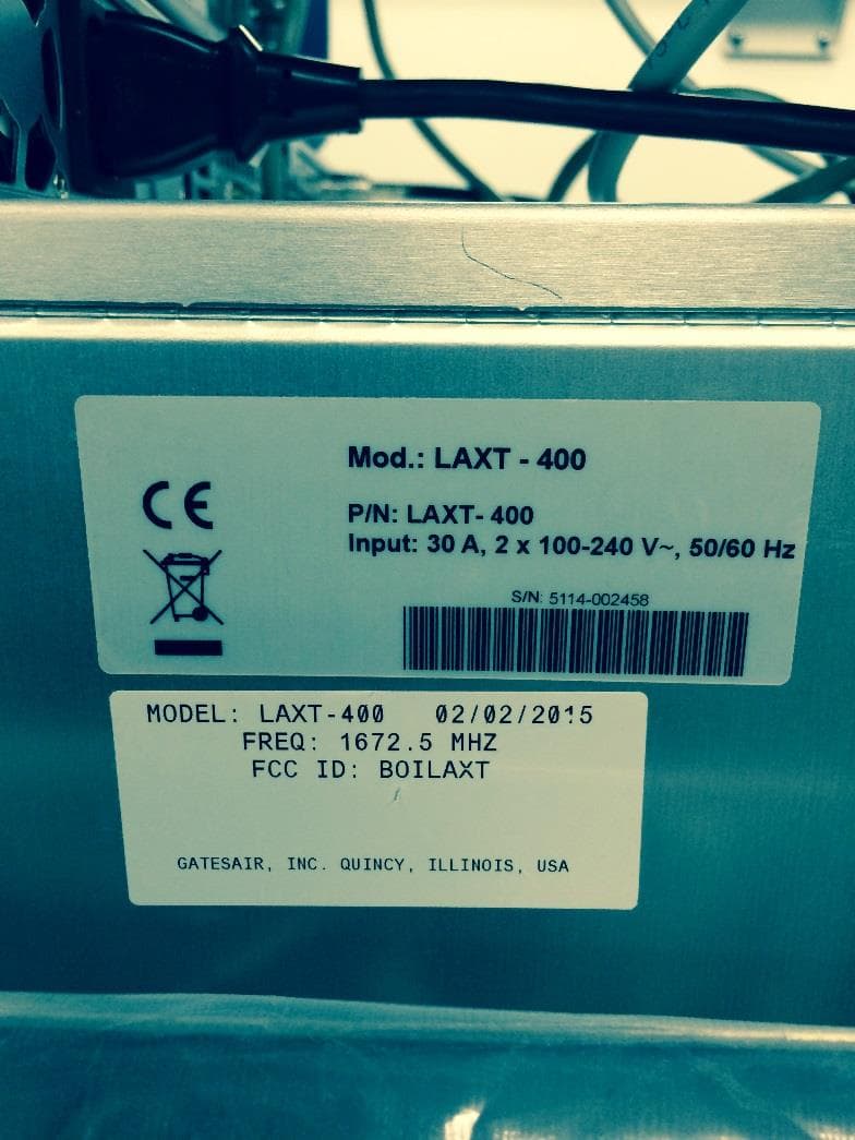
BOILAXT
Apr 23, 2015Maxiva LAXT Digital Television Transmitter
Equipment Class
TNB - Licensed Non-Broadcast Station Transmitter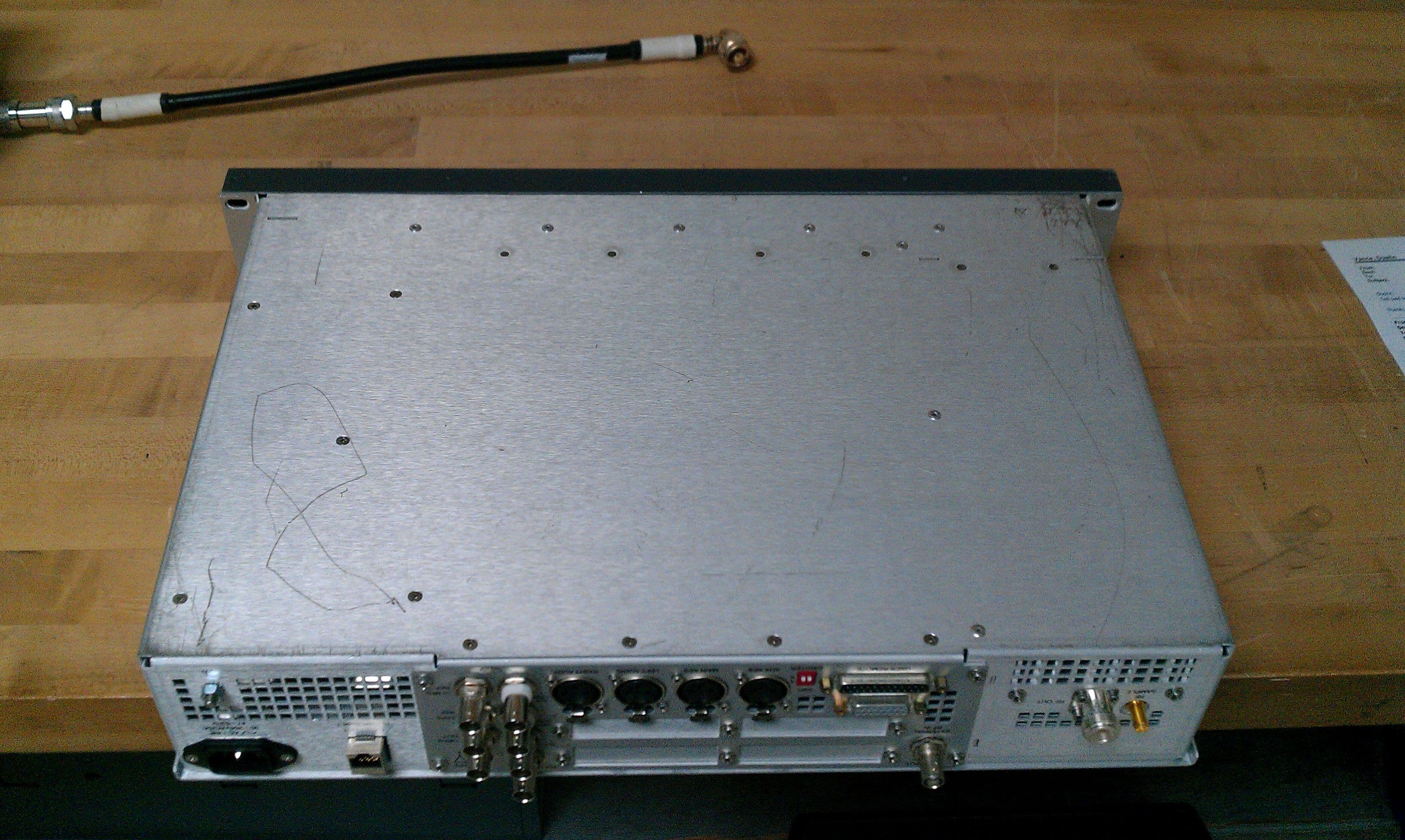
BOIFAXLP
Feb 04, 2014Flexiva Air-Cooled FM Transmitter/Exciter for Analog and Digital Standards Compact Class, Low Power - 50 W to 3.5 kW
Equipment Class
TBC - Licensed Broadcast Station Transmitter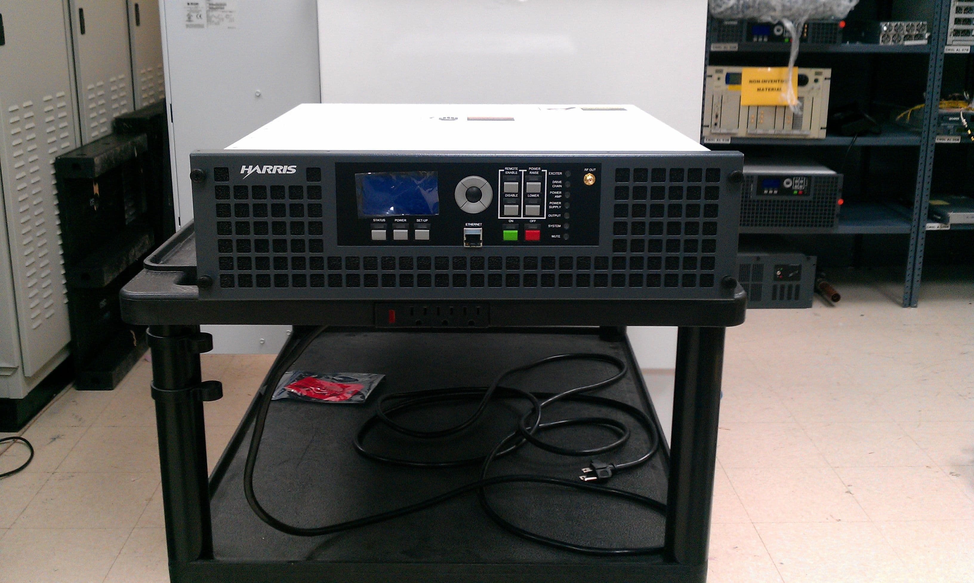
BOIFAXMP
Feb 03, 2014Air-Cooled FM Transmitter for Analog and Digital Standards Compact Class, Low Power
Equipment Class
TBC - Licensed Broadcast Station Transmitter
BOI-UAXFLID
Oct 25, 2010Maxiva UAX Transmitter Indoor System
Equipment Class
TNB - Licensed Non-Broadcast Station Transmitter