BSYKS395Cordless Microphone System
GMT Industrial Ltd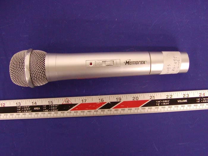
Click to zoom
Application Details
- Equipment Class
- TNF - Licensed Non-Broadcast Transmitter Held to Face
- Date of Grant
- Feb 04, 2004
- Application Purpose
- Original Equipment
- Date of Application
- Feb 04, 2004
- Equipment Note
- Cordless Microphone System
- Frequency Range
- 171.04500000 - 171.04500000
- Company
- GMT Industrial Ltd
- Country
- Hong Kong
Documents & Files
Document Text
Text extracted from the exhibit documents filed with the FCC. Open a document above to read the original.
Users Manual
CMATCL Owners Manual/Operating Instructions CMATCL, model KS395/MKA381 General....... The CMATCL, KS395/MKA381 is a hand held Transmitter operating within the FCC part 90 frequency range. The transmitter is especially suited for use wherever a small, reliable hand held wireless microphone is required. Versions are available with optional microphone capsules. Please note that each transmitter requires a matching receiver on the same frequency. Standard “off the shelf” frequencies are available. The CMATCL KS395/MKA381 features single channel crystal controlled units for the ultimate stability and clarity as well as economy. Setup: Before setting up the transmitter, it is necessary to setup the receiver or at least check the receiver operation if the receiver has been installed previously. Place the receiver in an area with the antennas in clear view of the transmitter operating area. Connect the receiver audio output to the audio input of the mixer, amplifier or other device. Turn the input to these items down at this point. Apply power to the receiver. Note that there should be no “Carrier” or TX light on at the receiver at this time. If there is a light on, this indicates that other users nearby may be using the frequency or that RF interference is present on the frequency. If the interference is not severe, suitable operation can sometimes be made possible by adjusting the squelch control until the light goes off. (Transmitter off) If the light cannot be made to go off by adjusting the squelch control, then the frequency should be changed. Set the receiver audio output control to its midpoint (50% of rotation). Open the transmitter battery door and install a fresh 9 volts alkaline battery. Place the transmitter in the position desired and turn on the power switch. The Green battery light should flash once and go off. The carrier light at the receiver should now be on. You are now ready to use the microphone. Place the transmitter mute switch in the on position (up). Talk in your normal tone and volume. If the Red light on the transmitter comes on or continues to flash as you speak, turn down the microphone gain control until the Red light is off or only flash’s on occasion. If the audio to the mixer or amplifier sounds distorted or clipped, try reducing the input volume of the mixer or amplifier, or turn the volume down on the receiver. FCC REGULATIONS The CMATCL, model KS395/MKA381 is a certification under United States Federal Communications Part 90. Licensing of CMATCL equipment is the users responsibility and license depends upon the users classification and the frequency selected. CMATCL strongly urges the user to contact the appropriate telecommunications authority before ordering frequencies other than factory preset frequency. CAUTION: Changes or modifications made by the user will void the user authority to use the equipment.
External Photos
GMT INDUSTRIAL LTD. FCC ID: BSYKS395 APPENDIX C - EUT PHOTOGRAPHS Chassis - Front View Chassis – Rear View
ID Label/Location Info
APPENDIX A - FCC ID LABELING AND LOCATION Proposed FCC ID Labeling Proposed FCC ID Location Rear Side of EUT, battery removed / Proposed Label Location The label is permenantly adhesive to the EUT. FCC ID: BSYKS395
Internal Photos
GMT INDUSTRIAL LTD. FCC ID: BSYKS395 Transmitter Board – Housing and Component View Transmitter Board – Component View GMT INDUSTRIAL LTD. FCC ID: BSYKS395 Transmitter Board – Solder View
Test Report
Note: This test report is specially limited to the above client company and product model. It may not be duplicated without prior written consent of Bay Area Compliance Laboratory Corporation. This report must not be used by the client to claim product endorsement by NVLAP or any agency of the U.S. Government. FCC PART 90 EMI MEASUREMENT AND TEST REPORT For GMT INDUSTRIAL LTD. UNIT 1006, 10/F., EASTERN CENTRE, 1065 KING’S ROAD, HONGKONG. FCC ID: BSYKS395 2004-01-21 This Report Concerns: Original Report Equipment Type: Cordless Microphone System Test Engineer: Ming Jin Report Number: R0312095 Test Date: 2003-12-23 Reviewed By: Ling Zhang Prepared By: Bay Area Compliance Laboratory Corporation 230 Commercial Street Sunnyvale, CA 94085 Tel: (408) 732-9162 Fax: (408) 732 9164 GMT INDUSTRIAL LTD. FCC ID: BSYKS395 Report # R0312095Rpt FCC Part 90 Test Report Page 2 of 22 TABLE OF CONTENTS GENERAL INFORMATION.......................................................................................................................................4 PRODUCT DESCRIPTION FOR EQUIPMENT UNDER TEST (EUT) ....................................................................................4 OBJECTIVE...................................................................................................................................................................4 RELATED GRANT/SUBMISSION.....................................................................................................................................4 TEST METHODOLOGY..................................................................................................................................................4 TEST FACILITY.............................................................................................................................................................4 SYSTEM TEST CONFIGURATION ..........................................................................................................................6 JUSTIFICATION.............................................................................................................................................................6 SPECIAL ACCESSORIES.................................................................................................................................................6 SCHEMATICS / BLOCK DIAGRAM.................................................................................................................................6 EQUIPMENT MODIFICATIONS.......................................................................................................................................6 CONFIGURATION OF TEST SYSTEM..............................................................................................................................7 TEST SETUP BLOCK DIAGRAM.....................................................................................................................................7 REQUIREMENTS OF PROVISIONS ........................................................................................................................8 REQUIREMENTS AND TEST SUMMARY.........................................................................................................................8 LABELING REQUIREMENT............................................................................................................................................8 §2.1046 AND §90.265(B)(2) - CONDUCTED OUTPUT POWER ............................................................................9 PROVISION APPLICABLE...............................................................................................................................................9 TEST PROCEDURE........................................................................................................................................................9 TEST EQUIPMENT.........................................................................................................................................................9 TEST RESULTS.............................................................................................................................................................9 §2.1047, §90.265(B) AND §90.210 (B) - MODULATION CHARACTERISTICS .................................................10 PROVISION APPLICABLE.............................................................................................................................................10 TEST PROCEDURE......................................................................................................................................................10 TEST EQUIPMENT.......................................................................................................................................................10 TEST RESULTS...........................................................................................................................................................10 §2.1049, §90.265(B)(1), AND §90.210 (B) - OCCUPIED BANDWIDTH OF EMISSION ....................................13 PROVISION APPLICABLE.............................................................................................................................................13 TEST PROCEDURE......................................................................................................................................................13 TEST EQUIPMENT.......................................................................................................................................................13 TEST RESULTS...........................................................................................................................................................13 §2.1051 AND §90.210(B) - RADIATED SPURIOUS EMISSION ...........................................................................16 PROVISION APPLICABLE........................................…
Text truncated - open the document above for the full version.
Test Setup Photos
GMT INDUSTRIAL LTD. FCC ID: BSYKS395 APPENDIX B - TEST SETUP PHOTOGRAPHS Radiated Emission - Front View Radiated Emission - Rear View
Contact Information
Applicant
S. Selvam
Test Firm
Bay Area Compliance LaboratoryJohn Chan
Technical Specifications
| # | Rule Parts | Frequency Range | Power Output | Emission | Tolerance |
|---|---|---|---|---|---|
| 1 | 90 | 171.045 MHz - 171.045 MHz | 22.00 mW | 26K0F3E | 50.0000000000 ppm |
Other Applications from GMT Industrial Ltd
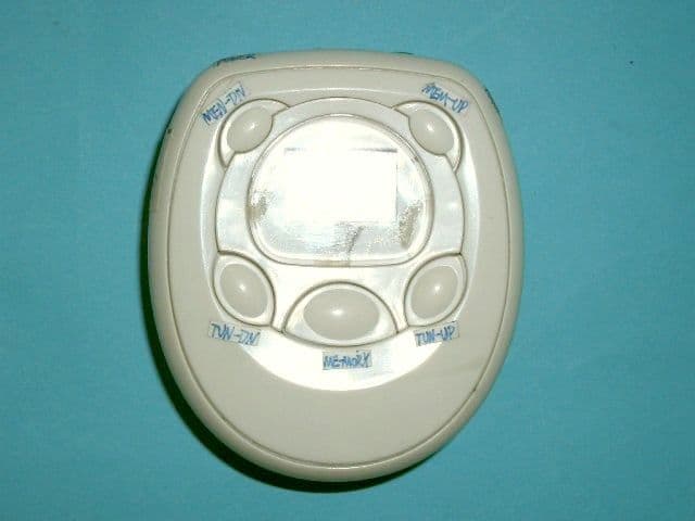
BSYRDT6806
Oct 28, 2007ARMBAND RADIO
Equipment Class
CYY - Communications Receiver used w/Pt 15 Transmitter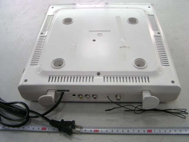
BSYKCL8806DT
Feb 21, 20067" cable LCD TV with Radio Weatherband Rx
Equipment Class
CXX - Communications Rcvr for use w/ licensed Tx and CBs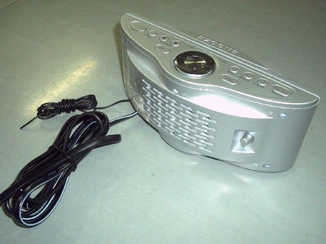
BSYCR6806DT
Feb 20, 2006DIGITAL TUNE AM/FM STEREO RADIO
Equipment Class
CXX - Communications Rcvr for use w/ licensed Tx and CBs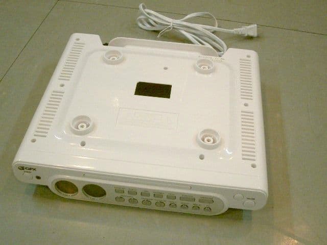
BSYKCCD6316DT
Feb 14, 2006Digital Tuner AM/ FM Stereo Radio
Equipment Class
CXX - Communications Rcvr for use w/ licensed Tx and CBs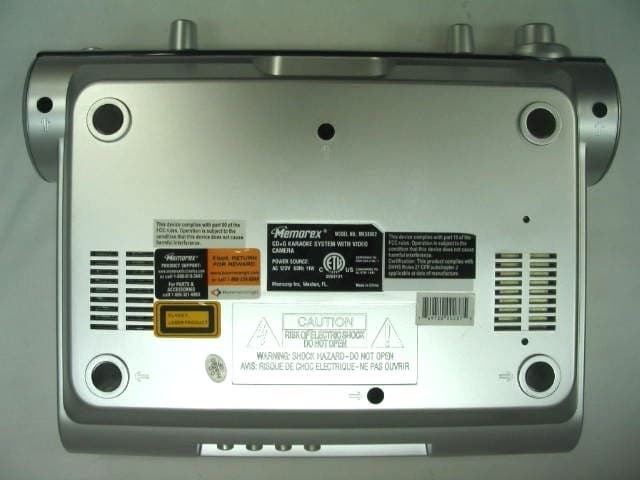
BSYKS359
Sep 19, 2004Set Top Box with Camera
Equipment Class
CXX - Communications Rcvr for use w/ licensed Tx and CBs