BV8CS803Digital Trunked Control Station
Harris Corporation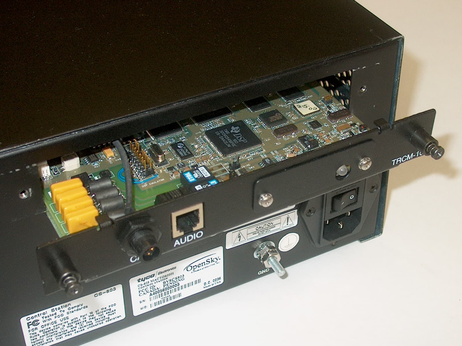
Click to zoom
Application Details
- Equipment Class
- TNB - Licensed Non-Broadcast Station Transmitter
- Date of Grant
- May 26, 2003
- Application Purpose
- Original Equipment
- Date of Application
- May 26, 2003
- Equipment Note
- Digital Trunked Control Station
- Frequency Range
- 806.00000000 - 824.00000000
- Company
- Harris Corporation
- Country
- United States
Documents & Files
Document Text
Text extracted from the exhibit documents filed with the FCC. Open a document above to read the original.
Users Manual
Operator’s Manual OpenSky CS-803/ SP-103/TRCM-103 Digital Trunked Control Station OpenSky is a registered trademark of M/A-COM, Inc. NOTICE! This manual covers M/A-COM products manufactured and sold by M/A- COM, Inc. NOTICE! Repairs to this equipment should be made only by an authorized service technician or facility designated by the supplier. Any repairs, alterations or substitutions of recommended parts made by the user to this equipment not approved by the manufacturer could void the user's authority to operate the equipment in addition to the manufacturer's warranty. This manual is published by M/A-COM, Inc., without any warranty. Improvements and changes to this manual necessitated by typographical errors, inaccuracies of current information, or improvements to programs and/or equipment, may be made by M/A-COM, Inc., at any time and without notice. Such changes will be incorporated into new editions of this manual. No part of this manual may be reproduced or transmitted in any form or by any means, electronic or mechanical, including photocopying and recording, for any purpose, without the express written permission of M/A-COM, Inc. Copyright 2003 M/A-COM, Inc. All rights reserved. 3 Proper Radio Use, Installation, and Service Introduction Use, installation, and service of the CS-803 radio as summarized below will ensure the safe performance of this equipment. Use of this radio as described below will result in user exposure substantially below the FCC recommended limits for human exposure to Radio Frequency Electromagnetic energy. Proper Use Do not operate this radio if any of the RF connectors are not secure or if open connections are not properly terminated. Proper Installation and Service The CS-803 radio and antenna must be professionally installed by experienced antenna installation professionals. During the installation of directional antennas, the installer must not point the main beam of the antenna to locations occupied by persons within the distance of maximum permissible exposure limits specified in Part 2 of the FCC regulations. Failure to follow these instructions will void the product warranty and may expose the end user and others to excessive Radio Frequency hazard. All antennas are intended to be installed outdoors and at distances from personnel well beyond the minimum allowable distance. Proper grounding is necessary, not only for correct functionality and maximum performance, but for minimizing damage that may occur from lightning strikes. The CS-803 radio and the SP-103 do not include a lightning-protection device, but it is recommended and only effective if the connection is made as the design intended. Follow the installation instructions to ensure a properly grounded unit. FCC regulations This device complies with Part 15 of the FCC Rules. Operation is subject to the following two conditions: (1) this device may not cause harmful interference; and (2) this device must accept any interference received, including interference that may cause undesired operation. This device is not required to comply with the FCC RF exposure limits for Uncontrolled Exposure (General Population) and Occupational Exposure, because it is assumed that neither uncontrolled nor occupational exposure is applicable in the general installation configuration. The installation of the antenna for the CS-803 is to be performed such that no person is within 10 meters during normal operation, and the CS-803 must be disabled before maintenance to the antenna is attempted. The Federal Communications Commission (FCC) requires the user to obtain a station license for this radio equipment before operating it. The operator is responsible at all times for the proper operation and maintenance of the equipment. FCC regulations state that the frequency, deviation, and power of a radio transmitter must be maintained within specified limits. It is recommended, therefore, that these three parameters be checked before the station is placed in service. 5 Important Safety Instructions 1) Read these instructions. 2) Keep these instructions. 3) Heed all warnings. 4) Follow all instructions. 5) Do not use this apparatus near water. 6) Clean only with dry cloth. 7) Do not block any ventilation openings. Install in accordance with the manufacturer’s instructions. 8) Do not install near any heat sources such as radiators, heat registers, stoves, or other apparatus (including amplifiers) that produce heat. 9) Do not defeat the safety purpose of the polarized or grounding-type plug. A polarized plug has two blades with one wider than the other. A grounding type plug has two blades and a third grounding prong. The wide blade or the third prong is provided for your safety. If the provided plug does not fit into your outlet, consult an electrician for replacement of the obsolete outlet. 10) Protect the power cord from being walked on or pinched particularly at plugs, convenience receptacles, and the point where they exit from the apparatus. 11) Only use attachments/accessories specified by the manufacturer. 12) Use only with the cart, stand, tripod, bracket, or table specified by the manufacturer, or sold with the apparatus. When a cart is used, use caution when moving the cart/apparatus combination to avoid injury from tip-over. 13) Unplug this apparatus during lightning storms or when unused for long periods of time. 14) Refer all servicing to qualified service personnel. Servicing is required when the apparatus has been damaged in any way, such as power-supply cord or plug is damaged, liquid has been spilled or objects have fallen into the apparatus, the apparatus has been exposed to rain or moisture, does not operate normally, or has been dropped. 15) Warning: The lightning bolt signifies an alert to the user of the presence of uninsulated “dangerous voltage” within the product’s enclosure that may be of significant magnitude to constitute a risk of electric shock to persons. 7 16) Warning: The exclamation point a…
Text truncated - open the document above for the full version.
Cover Letter(s)
M/A-COM, Inc. 221 Jefferson Ridge Parkway Lynchburg, VA 24501 [email protected] Regulatory Manager Telephone: (434) 455-9377 Fax: (434) 455-6815 May 15, 2003 Federal Communications Commission Authorization & Evaluation Division 7435 Oakland Mills Road Columbia Maryland 21046 Attention: To Whom it may concern Subject: Type Acceptance FCC ID: BV8CS803 M/A –COM, Inc. wishes the certification of the BV8CS803 control basestation to Part 90 of the 47 CFR. M/A-COM, Inc. wishes to submit this confidentiality letter for the record for FCC ID:BV8CS803 M/A-COM, Inc. is requesting that Exhibit 4 (Circuit Descriptions), Exhibit 5 (Schematic Diagrams), Exhibit 10 (Parts List and Tune Up Procedures), and Exhibit 12 (Operational Description) not be made routinely available for public inspection. M/A-COM, Inc. considers the information in these exhibits to be classified as trade secrets, pursuant to 47 CFR Section 0.457(d) and Section 552(b)(4) of the Freedom of Information Act. Please mark Exhibits 4, 5, 10, and 12 as “Confidential.” Regards, Bryan McWatters M/A-COM, Inc. Engineering Regulatory Manager 221 Jefferson Ridge Parkway Lynchburg VA, 24501 (434)455-9377 Fax(434)455-6815 [email protected]
Cover Letter(s)
M/A-COM, Inc. 221 Jefferson Ridge Parkway Lynchburg, VA 24501 [email protected] Regulatory Manager Telephone: (434) 455-9377 Fax: (434) 455-6815 May 15, 2003 Federal Communications Commission Authorization & Evaluation Division 7435 Oakland Mills Road Columbia Maryland 21046 Attention: To Whom it may concern Subject: Type Acceptance FCC ID: BV8CS803 M/A –COM, Inc. wishes the certification of the BV8CS803 control basestation to Part 90 of the 47 CFR. The product in question is an full duplex, 18 watt, 806-824 MHz control station, as such we are filing it as a basestation under part 90 rules. RF safety was not addressed except in a generic matter as this is a licensee issue on a basestation. Regards, Bryan McWatters M/A-COM, Inc. Engineering Regulatory Manager 221 Jefferson Ridge Parkway Lynchburg VA, 24501 (434)455-9377 Fax(434)455-6815 [email protected]
Cover Letter(s)
American Telecommunications Certification Body Inc. 6731 Whittier Ave, McLean, VA 22101 May 19, 2003 RE: FCC ID: BV8CS803 Attention: Bryan McWatters I have a few comments on this Application. 1. Please note that on page 10 of the report in section 6.1 you state that you used a double-ridged horn antenna then you state you adjusted by 2.14 for a dipole. Please explain. 2. Please note that on page 10 of the report in section 6.1 you state a distance correction factor of 20dB. Please note the limits are for 3 meters. Shouldn’t this be 10dB from 10 meter to 3 meters? Please explain. 3. Your 731 states TNB as the equipment code then just above this designation you state “Held to face”. Please correct the 731. Dennis Ward mailto:[email protected] The items indicated above must be submitted before processing can continue on the above referenced application. Failure to provide the requested information may result in application termination. Correspondence should be considered part of the permanent submission and may be viewed from the Internet after a Grant of Equipment Authorization is issued. Please do not respond to this correspondence using the email reply button. In order for your response to be processed expeditiously, you must submit your documents through the AmericanTCB.com website. Also, please note that partial responses increase processing time and should not be submitted. Any questions about the content of this correspondence should be directed to the sender.
Cover Letter(s)
ITS answers 1) We followed the procedures of EIA/TIA 603 for radiated spurious emissions. The substitution method using a half wave dipole is called out. The standard goes on to state that other antenna types are allowed, provided they can be referenced to a half wave dipole. Since we used a horn antenna above 1 GHz, we adjusted the readings by the additional gain of the transmit horn above that of a typical dipole (2.14 dBi). 2) The limits specified are not written at 3 meters. Instead we are comparing spurious radiated emissions to the 90.210 emissions mask requirement that all emissions offset by 250% or more of the transmitter bandwidth must be attenuated by 43 + 10 Log P(mW) dB below the fundamental power. Therefore limits are specified at the antenna port. We applied this limit (which calculates very conveniently to -13 dBm) to the EIRP values obtained using the substitution method. Note that the actual readings are compared to the actual limit of -13 dBm, and comply (scaling was only used in selection criterion, not EIRP results). Note also that the selected emissions tested were the highest emissions of all the spurious, so any other spurious would meet the requirements. The 20 dB distance scaling factor is part of a poorly thought out selection criterion to attempt to select the highest emissions since they are most likely to be non-compliant, yet pass over the emissions which are low enough not to require measurement. The selection criterion was simply that we wanted to measure any emissions within 20 dB of the limit, so any emission over -33 dBm. However, the limit was specified at the antenna port as stated above, and measurements were being made at 10 meters. Since 1 meter is close to the EUT, and we were measuring at ten meters from the EUT, an additional adjustment of 20 dB scaling to the -33 dBm selection criterion was made to account for the fact that the emissions seen at 10m would be lower than at 1m. Therefore the selection criterion was -53 dBm adjusted for the dipole that was assumed to be there as part of the procedure, or ~2.2 db gain, giving a selection threshhold of any emission over 51.8 dBuV (-53 dBm + 107 = 54 dBuV) [54 dBuV - 2.2 dB gain = 51.8 dBuV]. We should have simply used -33 dBm/ 4*Pi*r^2 but we did not, however the methodology employed is still correct from a substitution testing standpoint, since substitution testing ignores test distance anyway the actual data was not adjusted for any distance factors and represents the highest level of spurious emissions from the device. Regards, Nicholas Abbondante Engineer Intertek ETL SEMKO 70 Codman Hill Road Page 1 ITS answers Boxborough, MA 01719 Tel (978)635-8542 * Fax (978)263-7086 The information contained in this electronic mail transmission is intended by ITS for the use of the named individual or entity to which it is directed and may contain information that is confidential or privileged. If you have received this electronic mail transmission in error, please delete it from your system without copying or forwarding it, and notify the sender of the error by reply email or call ITS at 978-263-2662 so that the sender's address records can be corrected. Page 2
Internal Photos
This exhibit contains the photographs of the M-803 MRU Full Duplex Transceiver Board. They are: Figure 1 FD Top View#1 Figure 2 FD Top View #2 Figure 3 FD Bottom View #1 Figure 4 FD Bottom View #2 Figure 1 FD Top View#1 Figure 2 FD Top View #2 Figure 3 FD Bottom View #1 Fi Figure 4 FD Bottom View #2
Internal Photos
This exhibit contains the photographs of the M-803 VTAC-RF Combiner Board. They are: Figure 1 RFC Top View#1 Figure 2 RFC Top View #2 Figure 3 RFC Bottom View Figure 1 RFC Top View#1 Figure 2 RFC Top View #2 Figure 3 RFC Bottom View
Test Report
A70 Codman Hill Road Boxborough MA 01719 M/A-Com, Model No. CS-803Date of Test: January 23-24, 2003 FCC ID: BV8CS803 Report # 30373772FCC Part 90 Table of Contents 1.0Summary of Tests..................................................................................................................................................3 2.0General Description..............................................................................................................................................4 2.1Product Description................................................................................................................................4 2.2Related Submittal(s) Grants....................................................................................................................4 2.3Test Facility..............................................................................................................................................5 2.4Test Equipment and Support Equipment.............................................................................................6 3.0RF Power Output....................................................................................................................................................7 3.1Test Procedure.........................................................................................................................................7 3.2Test Results..............................................................................................................................................7 4.0Occupied Bandwidth, Bandwidth Limitation, Emission Masks.....................................................................8 4.1Test Procedure.........................................................................................................................................8 4.2Test Results..............................................................................................................................................8 5.0Out-of-Band Emissions at Antenna Terminals................................................................................................9 5.1Test Procedure.........................................................................................................................................9 5.2Test Results..............................................................................................................................................9 6.0 Field Strength of Spurious Radiation................................................................................................................10 6.1Test Procedure.......................................................................................................................................10 6.2Test Results............................................................................................................................................11 7.0 Frequency Stability vs Temperature..............................................................................................................12 7.1Test Procedure.......................................................................................................................................12 7.2Test Results............................................................................................................................................12 8.0 Frequency Stability vs Voltage........................................................................................................................13 8.1Test Procedure.......................................................................................................................................13 8.2Test Results............................................................................................................................................13 9.0Transient Frequency Behavior.........................................................................................................................14 9.1Test Procedure.......................................................................................................................................14 9.2Test Results............................................................................................................................................14 A70 Codman Hill Road Boxborough MA 01719 M/A-Com, Model No. CS-803Date of Test: January 23-24, 2003 FCC ID: BV8CS803 Report # 30373774FCC Part 90 2.0General Description 2.1Product Description The CS-803 Control Station is a versatile voice and data radio designed for the office environment. The CS-803 operates in the 800 MHz SMR frequency band. A production version of the CS-803 Control Station was received on January 23, 2003 in good condition, with serial number A40058000005. Only the OpenSky digital modulation (OTP/ORP which employs a GSFK modulation) software was provided and tested. The EUT has been tested at the request of Company:M/A-Com 1011 Pawtucket Blvd. Lowell, MA, 01853-2395 Name of contact:Andy Moysenko Telephone:(978) 442-4762 Fax:(978) 442-5442 Overview of CS-803 CS-803 Unit ApplicantM/A-Com Trade NameCS-803 Control Station FCC IdentifierBV8CS803 Use of ProductVoice and Data Communication Type of ModulationGFSK and FM Bit Rate19200 bps Baud Rate9600 Occupied Bandwidth16.5 kHz measured RF Output17.4 Watts measured DC voltage and current into the final RF amplifying device Voltage: 12VDC Current: 9A Frequency Range806 – 824 MHz Transmitter L.O. Frequency736 – 754 MHz, 921 – 939 MHz, 966 – 984 MHz Max. Number of Channels830 Antenna(e) & Gain0 dBd and 3 dBd Detachable Antenna?[X] Yes [ ] No Receiver L.O. Frequency58 MHz, 70.455 MHz, 736 – 754 MHz, 921 – 939 MHz, 966 – 984 MHz External Input[X] Audio [X] Digital Data A70 Codman Hill Road Boxborough MA 01719 M/A-Com, Model No. CS-803Date of Test: January 23-24, 2003 FCC ID: BV8CS803 Report # 30373775FCC Part 90 2.2Related Submittal(s) Grants None. 2.3Test Facility S…
Text truncated - open the document above for the full version.
Contact Information
Applicant
Thomas Camper, Jr.(Regulatory Manager)
Technical Contact
M/A COM, Inc.Bryan McWatters
[email protected](434)455-9377
221 Jefferson Ridge Parkway · Lynchburg, Virginia · United States
Technical Specifications
| # | Rule Parts | Frequency Range | Power Output | Emission | Tolerance |
|---|---|---|---|---|---|
| 2 | 9 | 806 MHz - 824 MHz | 17.4 W | 16K5F7E | 1.5 ppm |
Other Applications from Harris Corporation
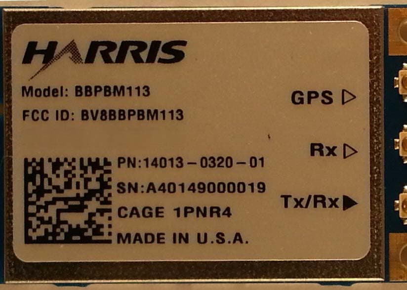
BV8BBPBM113
Apr 11, 2013Wireless Licensed Module
Equipment Class
TNB - Licensed Non-Broadcast Station Transmitter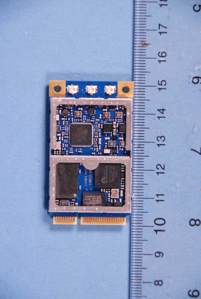
BV8BBPBM100
Feb 09, 2012700 MHz LTE Wireless Module
Equipment Class
TNB - Licensed Non-Broadcast Station Transmitter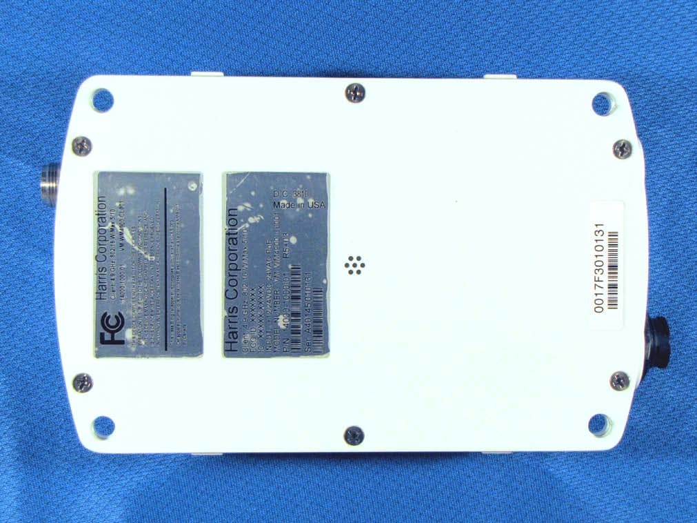
BV8WM4900CL
Nov 21, 2010Client 4.9 GHz 802.16 VBB 5/10
Equipment Class
TNB - Licensed Non-Broadcast Station Transmitter
BV8VIDA-BB-CL
Apr 11, 2007VIDA Broadband High Power Client
Equipment Class
TNB - Licensed Non-Broadcast Station Transmitter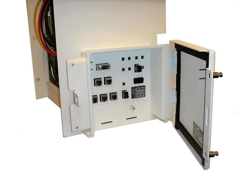
BV8CS900
Apr 08, 2007OpenSky 900 MHz Cell Site
Equipment Class
TNB - Licensed Non-Broadcast Station Transmitter