BV8M803MOpenSky M-803 Mobile Radio Systems
Harris Corporation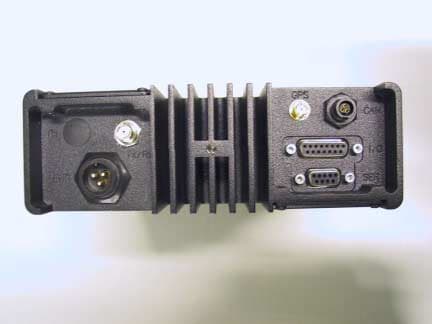
Click to zoom
Application Details
- Equipment Class
- TNB - Licensed Non-Broadcast Station Transmitter
- Date of Grant
- Oct 14, 2001
- Application Purpose
- Original Equipment
- Date of Application
- Aug 20, 2001
- Equipment Note
- OpenSky M-803 Mobile Radio Systems
- Frequency Range
- 806.00000000 - 824.00000000
- Company
- Harris Corporation
- Country
- United States
Documents & Files
Document Text
Text extracted from the exhibit documents filed with the FCC. Open a document above to read the original.
Users Manual
WINST-0004 Rev AWIRELESS SYSTEM BUSINESS UNIT SUBJECT: M-803 Dash-Mount Installation InstructionsDATE: August 16, 2001 Page 1 of 14 COPYRIGHT ©2001Printed in U.S.A. M/A-COM 1011 Pawtucket Boulevard Lowell, MA 01853 1-877-OPENSKY (1-877-673-6759) 1-877-OPENSKY O VERVIEW This document describes the procedure for installing the M/A-COM OpenSky ® Model M-803 Dash-Mount Mobile Radio in a vehicle, such as an automobile, truck, or van. This is a general guide only, and assumes that the installation will be performed by a professional radio installer. M ATERIALS The M-803 Dash-Mount Radio is designed to mount under or onto the dash inside the passenger compartment of a vehicle. The installation kit (M/A-COM Part No. MAMROS0017) needed to install the Radio is described below. The following table describes the different accessories that are included in the kit: Table I – Installation Kit Items ItemQtyPart NumberDescription 111000003774Dash-Mount Bracket 211000005187-0001Unity Gain Antenna, Quarter-wave 311000005809-0002Fuse Kit, 15A 411000005824-0002DC Power Cable (3m) 511000005828-0002Speaker Cable Assembly 611000005928-0001Microphone Head 711000005975-0002Microphone Cable Assembly 81AD00006Pkg. of 4 Screws, #8-32 PAN HD, Black 91M5240CAN Terminator, 3-Pin 101CTC-000261Speaker 111MAMROS00023GPS Antenna Kit* * GPS Antenna Kit is only included if the corresponding radio is equipped with an optional GPS Unit. I NSTRUCTIONS Upon removing all items from the box and verifying that all have been included, follow the following steps to install the M-803 Dash-Mount Radio. Refer to Figure 1 for location of connectors on the Radio. WINST-0004 Rev AWIRELESS SYSTEM BUSINESS UNIT SUBJECT: M-803 Dash-Mount Installation InstructionsDATE: August 16, 2001 Page 2 of 14 COPYRIGHT ©2001Printed in U.S.A. M/A-COM 1011 Pawtucket Boulevard Lowell, MA 01853 1-877-OPENSKY (1-877-673-6759) 1-877-OPENSKY Figure 1 Rear Panel ActionsNotes 1. Plan the mounting locations of all components (Radio, Speaker, Microphone, and Antenna), and determine the routes for all wiring and cables. Determine the customer’s preferences, if any, for location of components. Comply with these preferences insofar as they are consistent with safety, manufacturer specifications, and generally accepted professional practices. Make certain that drilling holes or inserting screws will not damage or interfere with any existing vehicle components or wiring. Follow all manufacturer requirements and guidelines for the location of components. 2. Mount the bracket in the interior of the vehicle. Mount the Bracket (Item 1) under or on top of the dash according to the available space in the vehicle. Screws for mounting the Bracket to the dash are not included, as all installations are different. The Bracket must be firmly held to the surface in order to prevent unreasonable vibration from damaging the Radio or loosening connections. For mounting on the transmission hump, select appropriate hardware such as a mounting wedge (not included in the Radio Installation Kit). 3. Mount the Radio onto the Bracket.Install the Mobile Radio into the Bracket using the 4 screws (Item 8) and tighten with a screwdriver until the bracket is firm and flush to the surface of the Radio. Speaker Connection Antenna Connections Power Connection CAN Port Connection GPS Antenna Connection WINST-0004 Rev AWIRELESS SYSTEM BUSINESS UNIT SUBJECT: M-803 Dash-Mount Installation InstructionsDATE: August 16, 2001 Page 3 of 14 COPYRIGHT ©2001Printed in U.S.A. M/A-COM 1011 Pawtucket Boulevard Lowell, MA 01853 1-877-OPENSKY (1-877-673-6759) 1-877-OPENSKY ActionsNotes 4. Assemble the Microphone Cable Assembly onto the Microphone Head. Connect the Microphone Cable Assembly (Item 7) to the Microphone Head (Item 6) by sliding the 2-pin connector of the cable into the cavity of the Microphone Head. Make sure the tab on the 2- pin connector is on the same side as the cable release hole on the back of the Microphone Head. You will hear a click if properly inserted. 5. Install the Microphone Assembly into the Mobile Radio. Plug the 14-pin connector of the Microphone Cable (Item 7) into the mating connector on the face of the Mobile Radio by aligning the connector appropriately and pushing. You will again hear a click if properly inserted. 6. Mount the Microphone Clip in the interior of the vehicle. The Microphone Clip is included in the package with the Microphone Head (Item 6). Ensure that the Microphone Clip is connected to the vehicle’s chassis ground by either screwing the mounting screws directly into the chassis or by providing a jumper wire to a lug that is attached to the Clip. The Radio has a monitor function that can be used when the Microphone is cradled in the Clip. 7. If an optional CH-103 Control Head is not being used with the M-803 Mobile Radio, a CAN Terminator needs to be installed. Install the CAN Terminator (Item 9) onto the 3- pin connector at the rear of the Radio by aligning the connector appropriately and twisting the outer housing clockwise until it stops. 8. Mount the Speaker in the interior of the vehicle and connect it to the Radio. Install the Speaker (Item 10) in an area of the front or rear dash that will allow for proper listening range for voice operation. Use the hardware and mounting bracket supplied with it. Refer to the Speaker manufacturer’s instructions included in the Speaker Assembly kit for additional installation guidance. Install the Speaker Cable Assembly (Item 5) onto the 15-pin connector at the rear of the Radio using a screwdriver. Do not over-tighten the screws. Connect the 2-pin connector on the Speaker (Item 10) to the mating connector on the Speaker Cable Assembly (Item 5). Route the excess WINST-0004 Rev AWIRELESS SYSTEM BUSINESS UNIT SUBJECT: M-803 Dash-Mount Installation InstructionsDATE: August 16, 2001 Page 4 of 14 COPYRIGHT ©2001Printed in U.S.A. M/A-COM 1011 Pawtucket Boulevard Lowell, MA 01853 1-877-OPENSKY (1-877-673-6759) 1-877-OPENSKY ActionsNot…
Text truncated - open the document above for the full version.
Users Manual
WINST-0005 Rev AWIRELESS SYSTEM BUSINESS UNIT SUBJECT: M-803 Trunk-Mount Installation InstructionsDATE: August 16, 2001 Page 1 of 13 COPYRIGHT ©2001Printed in U.S.A. M/A-COM 1011 Pawtucket Boulevard Lowell, MA 01853 1-877-OPENSKY (1-877-673-6759) 1-877-OPENSKY O VERVIEW This document describes the procedure for installing the M/A-COM OpenSky ® Model M-803 Trunk-Mount Mobile Radio in a vehicle, such as an automobile, truck, or van. This is a general guide only, and assumes that the installation will be performed by a professional radio installer. M ATERIALS The M-803 Trunk-Mount Radio is designed to mount on the floor or on a tray in the trunk or unoccupied section of a vehicle. The installation kit (M/A-COM Part No. MAMROS0018) needed to install the radio is described below. The following table describes the different accessories that are included in the kit: Table I ItemQtyPart NumberDescription 111000003678Base Bracket 211000005187-0001Unity Gain Antenna, Quarter-wave 311000005809-0002Fuse Kit, 15A 411000005824-0002DC Power Cable (3m) 511000005656-0001CAN Terminator, DB25M 62AD00006Pkg. of 4 Screws, #8-32 PAN HD, Black 71MAMROS00023GPS Antenna Kit* * GPS Antenna Kit is only included if the corresponding radio is equipped with an optional GPS Unit. I NSTRUCTIONS Upon removing all items from the box and verifying that all have been included, follow the following steps to install the M-803 Trunk-Mount Radio. Refer to Figure 1 for location of connectors on the Radio. WINST-0005 Rev AWIRELESS SYSTEM BUSINESS UNIT SUBJECT: M-803 Trunk-Mount Installation InstructionsDATE: August 16, 2001 Page 2 of 13 COPYRIGHT ©2001Printed in U.S.A. M/A-COM 1011 Pawtucket Boulevard Lowell, MA 01853 1-877-OPENSKY (1-877-673-6759) 1-877-OPENSKY Figure 1 Rear Panel ActionsNotes 1. Plan the mounting locations of all components (Radio, Antenna, and Cables) and determine the routes for all wiring and cables. Determine the customer’s preferences, if any, for location of components. Comply with these preferences insofar as they are consistent with safety, manufacturer specifications, and generally accepted professional practices. Make certain that drilling holes or inserting screws will not damage or interfere with any existing vehicle components or wiring. Follow all manufacturer requirements and guidelines for the location of components. 2. Mount the bracket in the interior of the vehicle. Mount the Base Bracket (Item 1) on top of the floor of the trunk according to the available space in the vehicle or on the surface of a trunk tray. Screws for mounting the bracket are not included, as all installations are different. The bracket must be firmly held to the surface in order to prevent unreasonable vibration from damaging the radio or loosening connections. 3. Mount the Radio onto the Bracket.Install the Mobile Radio into the bracket using the 6 screws (Item 8) and tighten with a screwdriver until the bracket is firm and flush to the surface of the radio. (Note: With 2 packages of 4 screws, there will be 2 extra screws.) 4. A CAN Terminator is needed to terminate the CAN Port. Install the CAN Terminator (Item 5) onto the front of the Radio and tighten the screws with a screwdriver. Speaker Connection Antenna Connections Power Connection CAN Port Connection GPS Antenna Connection WINST-0005 Rev AWIRELESS SYSTEM BUSINESS UNIT SUBJECT: M-803 Trunk-Mount Installation InstructionsDATE: August 16, 2001 Page 3 of 13 COPYRIGHT ©2001Printed in U.S.A. M/A-COM 1011 Pawtucket Boulevard Lowell, MA 01853 1-877-OPENSKY (1-877-673-6759) 1-877-OPENSKY ActionsNotes 5. Mount the Antenna at a suitable location on the vehicle, and route the Antenna Cable inside the vehicle for connection to the Radio. The Antenna (Item 2) that is included in the kit must be mounted by drilling a hole. The optimal position of the antenna is in the direct center of the roof of the vehicle. Refer to Antenna Mounting Configurations for requirements necessary to follow when selecting the proper mounting area for the antenna. Also, refer to the antenna manufacturer’s mounting and testing instructions included in the Antenna Assembly kit for installation guidance once the mounting area is determined. Route the cable from the Antenna (Item 2) to the rear of the Radio out of the way of casual contact. Install the Mini-UHF connector of the cable to the mating connector at the rear of the cable by tightening until finger-tight. It is important that this connector is tight to prevent RF leakage from occurring, but not too tight that damage occurs. Do not connect the antenna cable to the Radio until satisfactory completion of testing into a dummy load (refer to Testing Into a Dummy Load ). 6. If an optional GPS unit is included in the Radio, the GPS Antenna needs to be connected to the Radio. Connect the SMA connector of the GPS Antenna (Item 11) cable to the SMA connector on the rear of the Radio and route the cable out of the way of casual contact. The GPS Antenna is to be mounted on the roof of the vehicle with one of the 3 mounting configurations: Show-Mount, No Show-Mount, and Magnetic Mount. The Antenna must be kept at least 1 foot from any other antenna mounted on the vehicle and have at least 6 inches of ground plane beneath it. 7. Prepare for connecting the power to the Radio through the vehicle’s firewall. Plan the cable route carefully, using an existing access hole through the engine firewall if possible. Alternatively, drill a new hole approximately 3/8" in diameter and install a rubber grommet to protect the cable. NOTE Improper installation of the antenna may lead not only to poor radio performance, but to harmful exposure as well. See Antenna Mounting Configurations below. WINST-0005 Rev AWIRELESS SYSTEM BUSINESS UNIT SUBJECT: M-803 Trunk-Mount Installation InstructionsDATE: August 16, 2001 Page 4 of 13 COPYRIGHT ©2001Printed in U.S.A. M/A-COM 1011 Pawtucket Boulevard Lowell, MA 01853 1-877-OPENSKY (1-877-673-6759) 1-877-OPENSKY ActionsNotes 8. The F…
Text truncated - open the document above for the full version.
Users Manual
M-803 Gemini Series Mobile Radio OTP 5.07 OCF 3.13 Revision History DateUpdated byDescription of change 08/14/01Dennis GiddingsNew Notice of Copyright This manual and the hardware and software it describes are copyright © 2001 M/A-COM, Inc. All rights reserved under the copyright laws of the United States and Canada and other laws. Without limiting the rights under copyright, no part of this document may be reproduced, stored in or introduced into a retrieval system, or transmitted in any form or by any means (electronic, mechanical, photocopying, recording, or otherwise), or for any purpose, without the express written permission of M/A-COM, Inc. The contents of this manual are not intended to and do not constitute a warranty of any sort. M/A-COM, Inc and Tyco Electronics specifically disclaim any implied warranties of merchantability or fitness for any particular purpose resulting from this manual. Information in this document is subject to change without notice. M/A- COM, Inc. reserves the right to revise and make changes to this manual (and to the Kensington product and software) from time to time without obligation to notify any person of, or to provide any person with, such revisions or changes. M/A-COM, Inc. and/or Tyco Electronics may have patents, patent applications, trademarks, copyrights, or other intellectual property rights covering subject matter in this document. Except as expressly provided in any written license agreement from M/A-COM, the furnishing of this document does not give you any license to these patents, trademarks, copyrights, or other intellectual property. ©2001 M/A-COM, Incorporated. All rights reserved. Document # TBSL.Part No. 000-0000 Printed in the United States of America Software Version OTP 5.07M-803 Operator Manual iii iiiiii iii Preface Notices to the User and Safety Training Information IMPORTANT INFORMATION ON SAFE AND OPTIMAL OPERATION. READ THIS BEFORE USING YOUR M-803 MOBILE RADIO WARNING Your M-803 radio generates RF electromagnetic energy during transmit mode. This radio is designed for and classified as “Occupational Use Only” meaning it must be used only during the course of employment by individuals aware of the hazards and the ways to minimize such hazards. This radio is NOT intended for use by the “General Population” in an uncontrolled environment. This radio has been tested and complies with the FCC RF exposure limits for “Occupational Use Only.” In addition, your M-803 radio complies with the following Standards and Guidelines with regard to RF energy and electromagnetic energy levels and evaluation of such levels for exposure to humans: • FCC OET Bulletin 65 Edition 97-01 Supplement C, Evaluating Compliance with FCC Guidelines for Human Exposure to Radio Frequency Electromagnetic Fields. • American National Standards Institute (C95.1 – 1992), IEEE Standard for Safety Levels with Respect to Human Exposure to Radio Frequency Electromagnetic Fields, 3kHz to 300 GHz. Use of this radio as described below will result in user exposure substantially below the FCC recommended limits for human exposure to Radio Frequency Electromagnetic energy. iv iviv ivM-803 Operator Manual Software Version OTP 5.07 Before operating this radio, be sure you: • Do not operate this radio if any of the RF connectors are not secure or if open connections are not properly terminated. • Do not operate this radio near electrical blasting caps or in an explosive atmosphere. This radio has been tested and complies with the FCC RF exposure limits for Uncontrolled Exposure and Occupational exposure. The difference is in the minimum safe distance that people must be away from the antenna when transmitting RF energy. To assure optimal radio performance and that human exposure to RF electromagnetic energy is within the guidelines, transmit only when people are at least the minimum distance away from a properly installed antenna. The following lists these minimal allowable distances: M-803 Radio Rated Power Antenna Gain Minimum Distance for Uncontrolled Exposure Minimum Distance for Occupational Exposure 45 dBm max, 43 dBm nominal 0 dB68.5 cm (27 inches) 30.6 cm (12 inches) 45 dBm max, 43 dBm nominal 3 dB97.6 cm (38.4 inches) 43.2 cm (17 inches) The radio must be serviced and installed only by a qualified technician. Be sure that the radio is properly grounded according to the installation instructions. Note on jump-starting: If you need to jump start an M- 803 equipped vehicle, the positive radio lead from the radio must be disconnected from the vehicle battery. Disconnecting the lead will prevent damage to the radio. This equipment generates or uses radio frequency energy. Changes or modifications to this equipment may cause harmful interference unless the modifications are expressly approved in the instruction manual. The user could lose the authority to operate this equipment if an unauthorized change or modification is made. Software Version OTP 5.07M-803 Operator Manual v vv v This equipment has been tested and found to comply with the limits for a Class B digital device pursuant to Part 15 of the FCC Rules. These limits are designed to provide reasonable protection against harmful interference in a residential installation. Government law prohibits the operation of unlicensed transmitters within the territories under government control. Illegal operation is punishable by fine or imprisonment or both. Refer service to qualified technicians only. Do not operate your transceiver in explosive atmospheres (gases, dust, fumes, etc.). Occupational Safety Guidelines and Safety Training Information CAUTION To ensure that your exposure to RF electromagnetic energy is within the FCC allowable limits for occupational use, always adhere to the following guidelines. Your M-803 Mobile Radio transmits using a remote antenna. When it is ON, it receives and also sends out radio frequency (RF) signals. In 1996, the Federal Communications commission (FCC) adopted RF exposure guideline…
Text truncated - open the document above for the full version.
External Photos
This exhibit contains the external photographs of the M-803 Dash Mount Mobile Radio (DMMR). They are: Figure 1 DMMR Radio Front View Figure 2 DMMR Radio Rear View Figure 3 DMMR Radio Top View Figure 4 DMMR Radio Bottom View Figure 5 DMMR Radio Right Side View Figure 6 DMMR Radio Left Side View Figure 1 DMMR Radio Front View Figure 2 DMMR Radio Rear View Figure 3 DMMR Radio Top View Figure 4 DMMR Radio Bottom View Figure 5 DMMR Radio Right Side View Figure 6 DMMR Radio Left Side View
External Photos
This exhibit contains the external photographs of the M-803 Control Head. They are: Figure 1 Control Head Front View Figure 2 Control Head Rear View Figure 3 Control Head Top View Figure 4 Control Head Bottom View Figure 5 Control Head Right Side View Figure 6 Control Head Left Side View Figure 1 Control Head Front View Figure 2 Control Head Rear View Figure 3 Control Head Top View Figure 4 Control Head Bottom View Figure 5 Control Head Right Side View Figure 6 Control Head Left Side View
External Photos
This exhibit contains the external photographs of the M-803 Trunk Mount Mobile Radio (TMMR). They are: Figure 1 TMMR Radio Front View Figure 2 TMMR Radio Rear View Figure 3 TMMR Radio Top View Figure 4 TMMR Radio Bottom View Figure 5 TMMR Radio Right Side View Figure 6 TMMR Radio Left Side View Figure 1 TMMR Radio Front View Figure 2 TMMR Radio Rear View Figure 3 TMMR Radio Top View Figure 4 TMMR Radio Bottom View Figure 5 TMMR Radio Right Side View Figure 6 TMMR Radio Left Side View
ID Label/Location Info
This exhibit contains the photographs of the FCC label and its location on the radio. They are: Figure 1 FCC Label Figure 2 Label Location on DMMR Radio Top Figure 1 FCC Label Figure 2 Label Location on DMMR Radio Top FCC Label L ocation
Internal Photos
This exhibit contains the photographs of the M-803 Dash Mount Mobile Radio (DMMR). They are: Figure 1 DMMR Radio Front View Figure 2 DMMR Radio Rear View Figure 3 DMMR Radio Top View Figure 4 DMMR Radio Bottom View Figure 5 DMMR Radio Right Side View Figure 6 DMMR Radio Left Side View Figure 7 Radio Top View with Cover Removed Figure 8 Radio Bottom View with Cover Removed Figure 9 HPA Board Bottom View Figure 10 HPA Board Top View Figure 11 XCVR Board Bottom View Figure 12 XCVR Board Top View Figure 13 PK Board Bottom View Figure 14 PK Board Top View Figure 15 CH Board Top View Figure 16 CH Board Bottom View Figure 17 Display Board Top View Figure 18 Display Board Bottom View Figure 1 DMMR Radio Front View Figure 2 DMMR Radio Rear View Figure 3 DMMR Radio Top View Figure 4 DMMR Radio Bottom View Figure 5 DMMR Radio Right Side View Figure 6 DMMR Radio Left Side View Figure 7 Radio Top View with Cover Removed HPA BOARDXCVR BOARD Figure 8 Radio Bottom View with Cover Removed PK BOARDGPS OPTION Figure 9 HPA Board Bottom View Figure 10 HPA Board View Top View Figure 11 XCVR Board Bottom View Figure 12 XCVR Board Top View Figure 13 PK Board Bottom View Figure 14 PK Board Top View Figure 15 CH Board Top View Figure 16 CH Board Bottom View Figure 17 Display Board Top View Figure 18 Display Board Bottom View
Internal Photos
This exhibit contains the photographs of the M-803 Control Head. They are: Figure 1 Control Head Front View Figure 2 Control Head Rear View Figure 3 Control Head Top View Figure 4 Control Head Bottom View Figure 5 Control Head Right Side View Figure 6 Control Head Left Side View Figure 7 Control Head Board Top View Figure 8 Control Head Board Bottom View Figure 9 Display Board Top View Figure 10 Display Board Bottom View Figure 11 CHPA Board Top View Figure 12 CHPA Board Bottom View Figure 1 Control Head Front View Figure 2 Control Head Rear View Figure 3 Control Head Top View Figure 4 Control Head Bottom View Figure 5 Control Head Right Side View Figure 6 Control Head Left Side View Figure 7 Control Head Board Top View Figure 8 Control Head Board Bottom View Figure 9 Display Board Top View Figure 10 Display Board Bottom View Figure 11 Display Board Top View Figure 12 Display Board Bottom View
Internal Photos
This exhibit contains the photographs of the M-803 Trunk Mount Mobile Radio (TMMR). They are: Figure 1 TMMR Radio Front View Figure 2 TMMR Radio Rear View Figure 3 TMMR Radio Top View Figure 4 TMMR Radio Bottom View Figure 5 TMMR Radio Right Side View Figure 6 TMMR Radio Left Side View Figure 7 Radio Top View with Cover Removed Figure 8 Radio Bottom View with Cover Removed Figure 9 HPA Board Bottom View Figure 10 HPA Board Top View Figure 11 XCVR Board Bottom View Figure 12 XCVR Board Top View Figure 13 PK Board Bottom View Figure 14 PK Board Top View Figure 1 TMMR Radio Front View Figure 2 TMMR Radio Rear View Figure 3 TMMR Radio Top View Figure 4 TMMR Radio Bottom View Figure 5 TMMR Radio Right Side View Figure 6 TMMR Radio Left Side View Figure 7 Radio Top View with Cover Removed HPA BOARDXCVR BOARD Figure 8 Radio Bottom View with Cover Removed PK BOARD GPS OPTION Figure 9 HPA Board Bottom View Figure 10 HPA Board View Top View Figure 11 XCVR Board Bottom View Figure 12 XCVR Board Top View Figure 13 PK Board Bottom View Figure 14 PK Board Top View
Contact Information
Applicant
Thomas Camper, Jr.(Regulatory Manager)
Technical Contact
M/A Com Inc.Bill Delaney
[email protected]9784425321
70 Codman Hill Road · Lowell, Massachusetts · United States
Non-Technical Contact
M/A Com Inc.Andy Moysenko
[email protected]9784424762
Test Firm
Intertek Testing Services NA Inc.Robert Martin
Technical Specifications
| # | Rule Parts | Frequency Range | Power Output | Emission | Tolerance |
|---|---|---|---|---|---|
| 1 | 90 | 806 MHz - 824 MHz | 25 W | 11K8F1E | 1.5000000000 ppm |
Other Applications from Harris Corporation
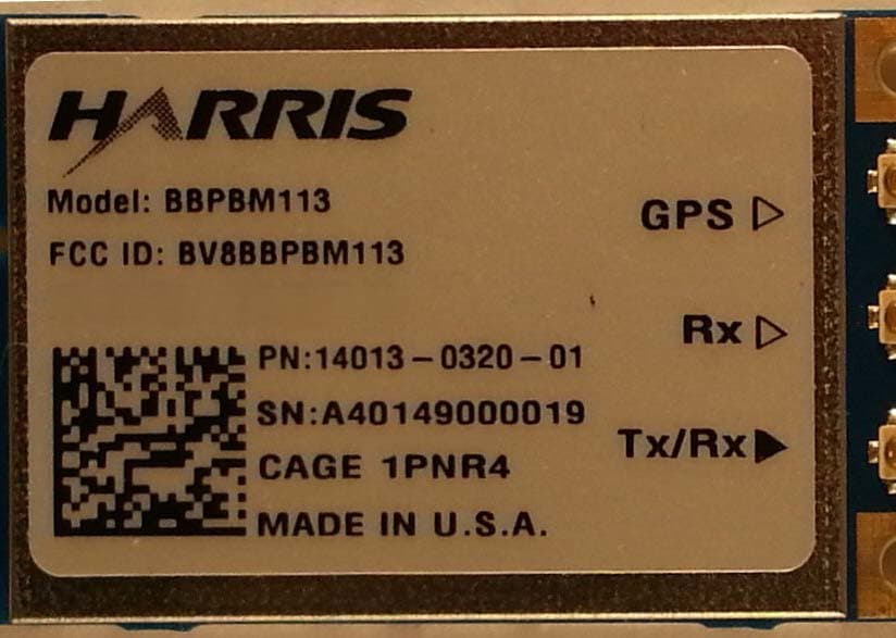
BV8BBPBM113
Apr 11, 2013Wireless Licensed Module
Equipment Class
TNB - Licensed Non-Broadcast Station Transmitter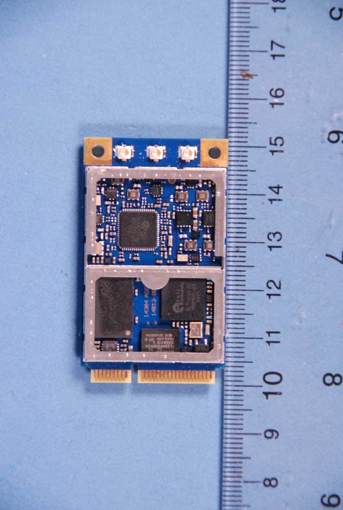
BV8BBPBM100
Feb 09, 2012700 MHz LTE Wireless Module
Equipment Class
TNB - Licensed Non-Broadcast Station Transmitter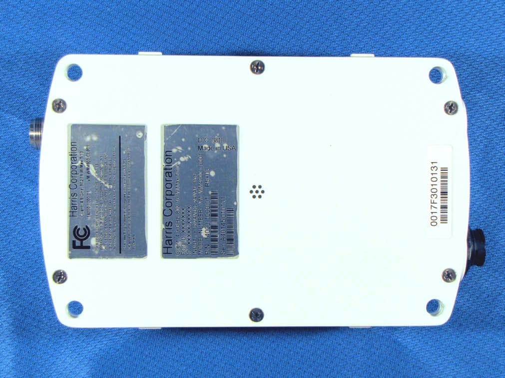
BV8WM4900CL
Nov 21, 2010Client 4.9 GHz 802.16 VBB 5/10
Equipment Class
TNB - Licensed Non-Broadcast Station Transmitter
BV8VIDA-BB-CL
Apr 11, 2007VIDA Broadband High Power Client
Equipment Class
TNB - Licensed Non-Broadcast Station Transmitter
BV8CS900
Apr 08, 2007OpenSky 900 MHz Cell Site
Equipment Class
TNB - Licensed Non-Broadcast Station Transmitter