BV8M803VTACM-803 Vehicular Tactical Unit (VTAC)
Harris Corporation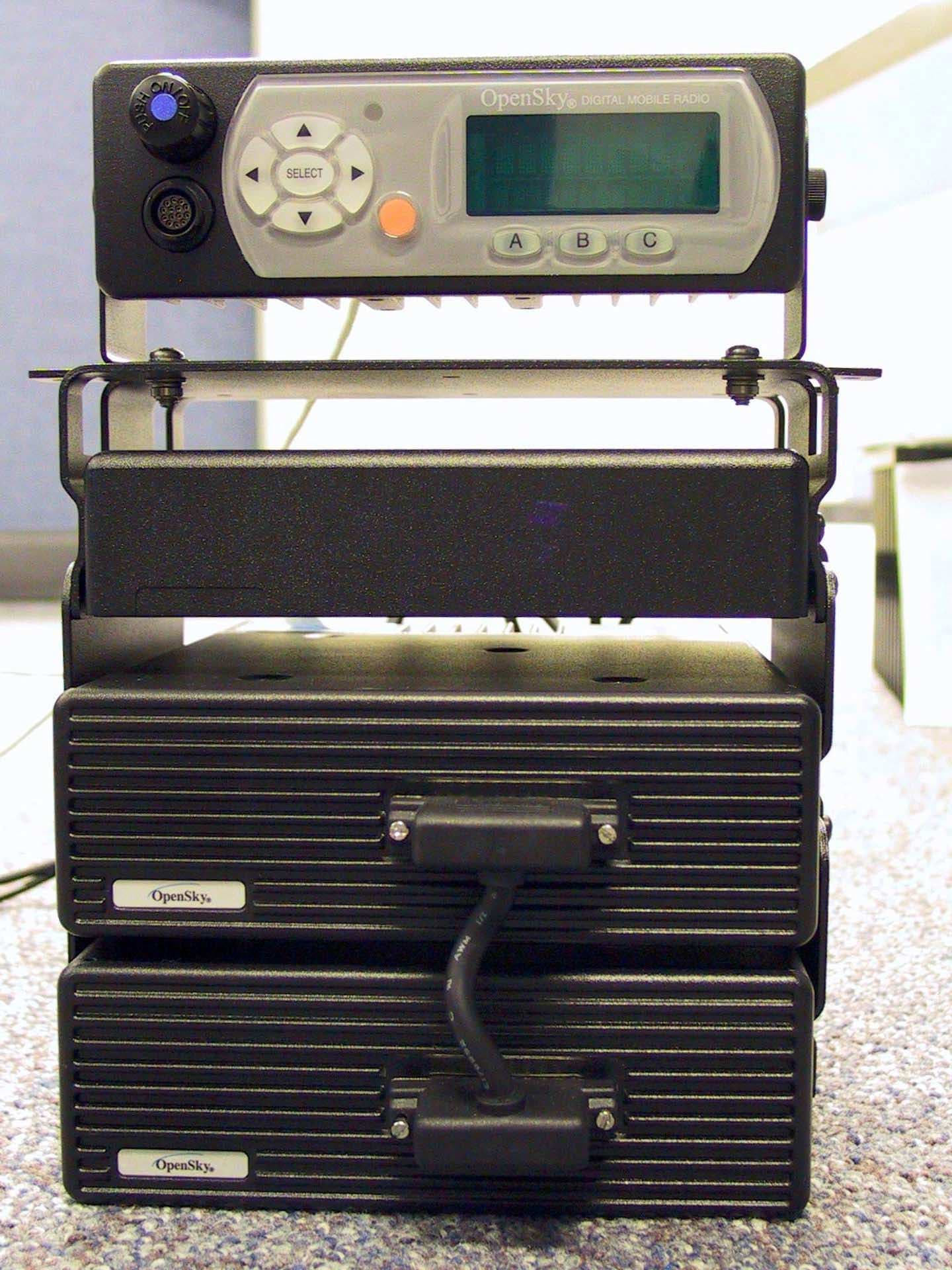
Click to zoom
Application Details
- Equipment Class
- TNB - Licensed Non-Broadcast Station Transmitter
- Date of Grant
- Sep 30, 2002
- Application Purpose
- Original Equipment
- Date of Application
- Feb 21, 2002
- Equipment Note
- M-803 Vehicular Tactical Unit (VTAC)
- Frequency Range
- 851.00000000 - 869.00000000
- Company
- Harris Corporation
- Country
- United States
Documents & Files
Document Text
Text extracted from the exhibit documents filed with the FCC. Open a document above to read the original.
Users Manual
M-803 Gemini Series Mobile Radio OTP 5.07 OCF 3.13 Revision History DateUpdated byDescription of change 08/14/01Dennis GiddingsNew Notice of Copyright This manual and the hardware and software it describes are copyright © 2001 M/A-COM, Inc. All rights reserved under the copyright laws of the United States and Canada and other laws. Without limiting the rights under copyright, no part of this document may be reproduced, stored in or introduced into a retrieval system, or transmitted in any form or by any means (electronic, mechanical, photocopying, recording, or otherwise), or for any purpose, without the express written permission of M/A-COM, Inc. The contents of this manual are not intended to and do not constitute a warranty of any sort. M/A-COM, Inc and Tyco Electronics specifically disclaim any implied warranties of merchantability or fitness for any particular purpose resulting from this manual. Information in this document is subject to change without notice. M/A- COM, Inc. reserves the right to revise and make changes to this manual (and to the Kensington product and software) from time to time without obligation to notify any person of, or to provide any person with, such revisions or changes. M/A-COM, Inc. and/or Tyco Electronics may have patents, patent applications, trademarks, copyrights, or other intellectual property rights covering subject matter in this document. Except as expressly provided in any written license agreement from M/A-COM, the furnishing of this document does not give you any license to these patents, trademarks, copyrights, or other intellectual property. ©2001 M/A-COM, Incorporated. All rights reserved. Document # TBSL.Part No. 000-0000 Printed in the United States of America Software Version OTP 5.07M-803 Operator Manual iii iiiiii iii Preface Notices to the User and Safety Training Information IMPORTANT INFORMATION ON SAFE AND OPTIMAL OPERATION. READ THIS BEFORE USING YOUR M-803 MOBILE RADIO WARNING Your M-803 radio generates RF electromagnetic energy during transmit mode. This radio is designed for and classified as “Occupational Use Only” meaning it must be used only during the course of employment by individuals aware of the hazards and the ways to minimize such hazards. This radio is NOT intended for use by the “General Population” in an uncontrolled environment. This radio has been tested and complies with the FCC RF exposure limits for “Occupational Use Only.” In addition, your M-803 radio complies with the following Standards and Guidelines with regard to RF energy and electromagnetic energy levels and evaluation of such levels for exposure to humans: • FCC OET Bulletin 65 Edition 97-01 Supplement C, Evaluating Compliance with FCC Guidelines for Human Exposure to Radio Frequency Electromagnetic Fields. • American National Standards Institute (C95.1 – 1992), IEEE Standard for Safety Levels with Respect to Human Exposure to Radio Frequency Electromagnetic Fields, 3kHz to 300 GHz. Use of this radio as described below will result in user exposure substantially below the FCC recommended limits for human exposure to Radio Frequency Electromagnetic energy. iv iviv ivM-803 Operator Manual Software Version OTP 5.07 Before operating this radio, be sure you: • Do not operate this radio if any of the RF connectors are not secure or if open connections are not properly terminated. • Do not operate this radio near electrical blasting caps or in an explosive atmosphere. This radio has been tested and complies with the FCC RF exposure limits for Uncontrolled Exposure and Occupational exposure. The difference is in the minimum safe distance that people must be away from the antenna when transmitting RF energy. To assure optimal radio performance and that human exposure to RF electromagnetic energy is within the guidelines, transmit only when people are at least the minimum distance away from a properly installed antenna. The following lists these minimal allowable distances: M-803 Radio Rated Power Antenna Gain Minimum Distance for Uncontrolled Exposure Minimum Distance for Occupational Exposure 45 dBm max, 43 dBm nominal 0 dB68.5 cm (27 inches) 30.6 cm (12 inches) 45 dBm max, 43 dBm nominal 3 dB97.6 cm (38.4 inches) 43.2 cm (17 inches) The radio must be serviced and installed only by a qualified technician. Be sure that the radio is properly grounded according to the installation instructions. Note on jump-starting: If you need to jump start an M- 803 equipped vehicle, the positive radio lead from the radio must be disconnected from the vehicle battery. Disconnecting the lead will prevent damage to the radio. This equipment generates or uses radio frequency energy. Changes or modifications to this equipment may cause harmful interference unless the modifications are expressly approved in the instruction manual. The user could lose the authority to operate this equipment if an unauthorized change or modification is made. Software Version OTP 5.07M-803 Operator Manual v vv v This equipment has been tested and found to comply with the limits for a Class B digital device pursuant to Part 15 of the FCC Rules. These limits are designed to provide reasonable protection against harmful interference in a residential installation. Government law prohibits the operation of unlicensed transmitters within the territories under government control. Illegal operation is punishable by fine or imprisonment or both. Refer service to qualified technicians only. Do not operate your transceiver in explosive atmospheres (gases, dust, fumes, etc.). Occupational Safety Guidelines and Safety Training Information CAUTION To ensure that your exposure to RF electromagnetic energy is within the FCC allowable limits for occupational use, always adhere to the following guidelines. Your M-803 Mobile Radio transmits using a remote antenna. When it is ON, it receives and also sends out radio frequency (RF) signals. In 1996, the Federal Communications commission (FCC) adopted RF exposure guideline…
Text truncated - open the document above for the full version.
Users Manual
WINST-0009 Rev –WIRELESS SYSTEM BUSINESS UNIT SUBJECT: M-803 VTAC Installation Instructions DATE: February 19, 2002 Page 1 of 19 COPYRIGHT ©2002Printed in U.S.A. M/A-COM 1011 Pawtucket Boulevard Lowell, MA 01853 1-877-OPENSKY (1-877-673-6759) 1-877-OPENSKY O VERVIEW This document describes the procedure for installing the M/A-COM OpenSky ® Model VR-803 Vehicular Tactical Network (V-TAC) in a vehicle, such as an automobile, truck, or van. This is a general guide only, and assumes that the installation will be performed by a professional radio installer. D ISCLAIMER THE INSTALLATION INSTRUCTIONS PROVIDED IN THIS MANUAL ARE FOR REFERENCE, AND DO NOT CREATE A WARRANTY OF ANY KIND AS TO THE FUNCTIONALITY OF THE INSTALLED PRODUCT. THE ONLY WARRANTIES THAT APPLY TO THIS PRODUCT ARE THOSE SET FORTH IN THE SALES AGREEMENT. M/A-COM INC. RECOMMENDS THAT BUYER USE ONLY A M/A-COM AUTHORIZED REPRESENTATIVE TO INSTALL THIS PRODUCT. THE WARRANTIES PROVIDED TO BUYER UNDER THE TERMS OF SALE SHALL BE NULL AND VOID IF THIS PRODUCT IS INSTALLED OR SERVICED IMPROPERLY, AND M/A-COM SHALL HAVE NO FURTHER OBLIGATION TO THE BUYER FOR ANY DAMAGE CAUSED TO THE PRODUCT OR TO ANY PERSON OR PERSONAL PROPERTY. M AT E RIAL S There are three main components to the VR-803 V-TAC: the Full-Duplex Mobile Radio Unit (MRU); the Vehicular Repeater Base Unit (VRB); and the RF Combiner. The V-TAC is designed to mount o n the floor or on a tray in the trunk or unoccupied section of a vehicle. The V-TAC is designed to be operated with an externally- mounted antenna. The Installatio n Kit (M/A-COM Part #MAMROS0019) needed to install the V-TAC is described below. The V-TAC is intended to be used with a CH- 103 Control Head with Installation Kit, sold separately. Table I lists the accessories that are included in the kit. Table II lists additio nal options and accessories that may be purchased separately. (Note: The Installation Kit does not include an antenna. An antenna must be purchased separately, and the V-TAC may not be installed unless an antenna is to be installed at the same time.) WINST-0009 Rev –WIRELESS SYSTEM BUSINESS UNIT SUBJECT: M-803 VTAC Installation Instructions DATE: February 19, 2002 Page 2 of 19 COPYRIGHT ©2002Printed in U.S.A. M/A-COM 1011 Pawtucket Boulevard Lowell, MA 01853 1-877-OPENSKY (1-877-673-6759) 1-877-OPENSKY IMPORTANT Table I – Installation Kit Items ItemQtyPart NumberDescription 11MAMROS0044Base Bracket Kit 22MAMROS0046Extensio n Bracket Kit 31MAMROS0068-0003Fuse Kit, 3A 42MAMROS0068-0015Fuse Kit, 15A 53MAMROS0051DC Power Cable, M-803 (20 ft) 61MAMROS0052Multi-Cable Assembly 71MAMROS0054V-TAC Control Interface Assembly 81MAMROS0078-TMB12RF Cable, TNC to Mini-UHF, Blue 91MAMROS0078-TMG12RF Cable, TNC to Mini-UHF, Green 101MAMROS0078-TTR12RF Cable, TNC to TNC, Red 111MAMROS0078-TTX12RF Cable, TNC to TNC, Yellow 121MAMROS0066CAN Terminator, 3-Pin 131MAMROS0060Antenna Connector, TNC Table II - Additional V-TAC Options and Accessories Part NumberDescription (TBD)GPS Upgrade Option MAMROS0023GPS Antenna Kit, Sho w/No-Show/Magnet Mount MAMROS0033Antenna Kit, Unity Gain, Rooftop MAMROS0031Antenna Kit, 3dB, Rooftop MAMROS0024Antenna Kit, Elevated 3dB, Trunk Mount MAMROS0039SMR/GPS Antenna Kit, 3dB, Rooftop MAMROS0026SMR/GPS Antenna Kit, Elevated 3dB, Trunk Mount MAMROS0042SMR/GPS Antenna Kit, Elevated 3dB, Mirror Mount MAMROS0055RS-232 Serial Computer Cable (6 ft) I NST RUCT IONS Upon removing all items from the box and verifying that all have been included, proceed with the following steps to install the VR-803 V-TAC. Refer to Figure 1 for location of connectors on the V-TAC. Mounting of the V-TAC and Antenna in ways other than those described below may adversely affect performance, violate FCC rules on RF Exposure, and even damage the V-TAC. WINST-0009 Rev –WIRELESS SYSTEM BUSINESS UNIT SUBJECT: M-803 VTAC Installation Instructions DATE: February 19, 2002 Page 3 of 19 COPYRIGHT ©2002Printed in U.S.A. M/A-COM 1011 Pawtucket Boulevard Lowell, MA 01853 1-877-OPENSKY (1-877-673-6759) 1-877-OPENSKY ActionsNotes 1. Plan the mounting locations of all components (V-TAC, Antenna, and Cables) and determine the routes for all wiring and cables. ♦ Determine the customer’s preferences, if any, for location of components. Comply with these preferences insofar as they are consistent with safety, manufacturer specifications, and generally accepted professional practices. ♦ Make certain that drilling holes or inserting screws will not damage or interfere with any existing vehicle components or wiring. ♦ Follow all manufacturer requirements and guidelines for the location of components. MRU VRB RF Combiner V-TAC Control Interface Assembly Multi-Cable Assembly D.C. Power Connections RS-232 Serial Port (SMA - Optional) GPS Antenna CAN Port Speaker Conne ction (Disa ble d) GPS Data Conne ction (O ptio nal) CAN Port (Terminated) A nte nna Port (TNC) Figure 1 - Front and Rear View s of VR-803 V-TAC WINST-0009 Rev –WIRELESS SYSTEM BUSINESS UNIT SUBJECT: M-803 VTAC Installation Instructions DATE: February 19, 2002 Page 4 of 19 COPYRIGHT ©2002Printed in U.S.A. M/A-COM 1011 Pawtucket Boulevard Lowell, MA 01853 1-877-OPENSKY (1-877-673-6759) 1-877-OPENSKY ActionsNotes 2. Mount the bracket in the interior of the vehicle. ♦ As an assembled unit, the V-TAC weighs over 20 lbs. It is unadvisable for the V-TAC to be hung from a surface; rather, the V-TAC is best mounted onto a firm, flat surface. ♦ Mount the Base Bracket from the Base Bracket Kit (Item 1) on top of the floor of the trunk according to the available space in the vehicle or on the surface of a trunk tray. ♦ Screws for mounting the bracket are not included, as all installations are different, but at least 6 screws are required. Steel #10 screws are recommended. ♦ Screws for mounting the MRU into the Base Bracket are included. ♦ The Bracket must be firmly held to the surface in order to prevent unreasonable vibration from damaging the V-TAC or connections from loosening. 3. Cre…
Text truncated - open the document above for the full version.
Cover Letter(s)
To whom it may concern, When I uploaded the 4 schematic files, I neglected to indicate that I wanted them to be held confidential. Currently they are downloadable from your website. Please make them confidential and nondownloadable. I have already submitted a formal confidentiality request outlining which documents are to be held confidential, and schematics are one of them. Thank you, Nicholas Abbondante
External Photos
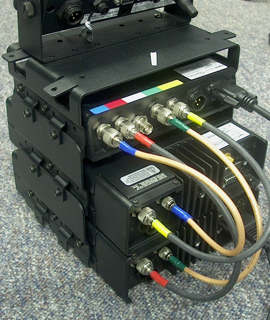
This exhibit contains the photographs 0f the M-803 V-TAC Assembly. They are: Figure 1 V-Tac Front View Figure 2 V-Tac Rear View #1 Figure 3 V-Tac Rear View #2 Figure 4 V-Tac Side View #1 Figure 5 V-Tac Side View #2 Figure 6 V-Tac Side View #3 Figure 1 V-Tac Front View Figure 2 V-Tac Rear View #1 Figure 3 V-Tac Rear View #2 Figure 4 V-Tac Side View #1 Figure 5 V-Tac Side View #2 Figure 6 V-Tac Side View #3
ID Label/Location Info
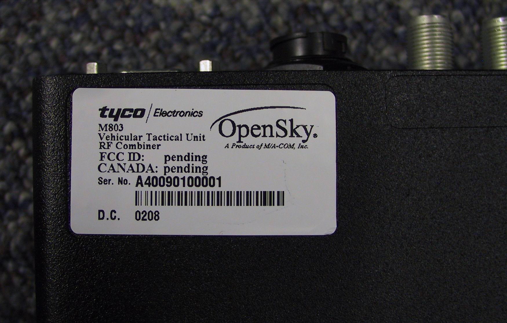
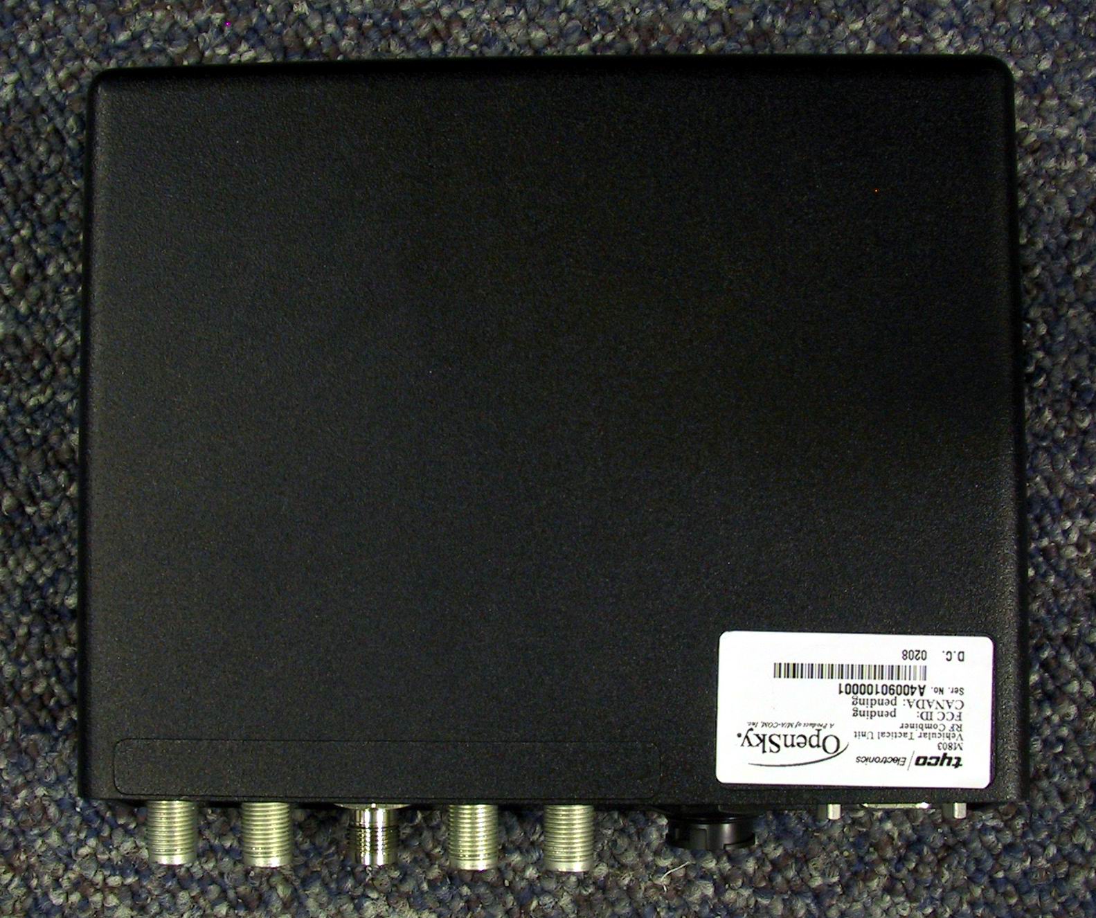
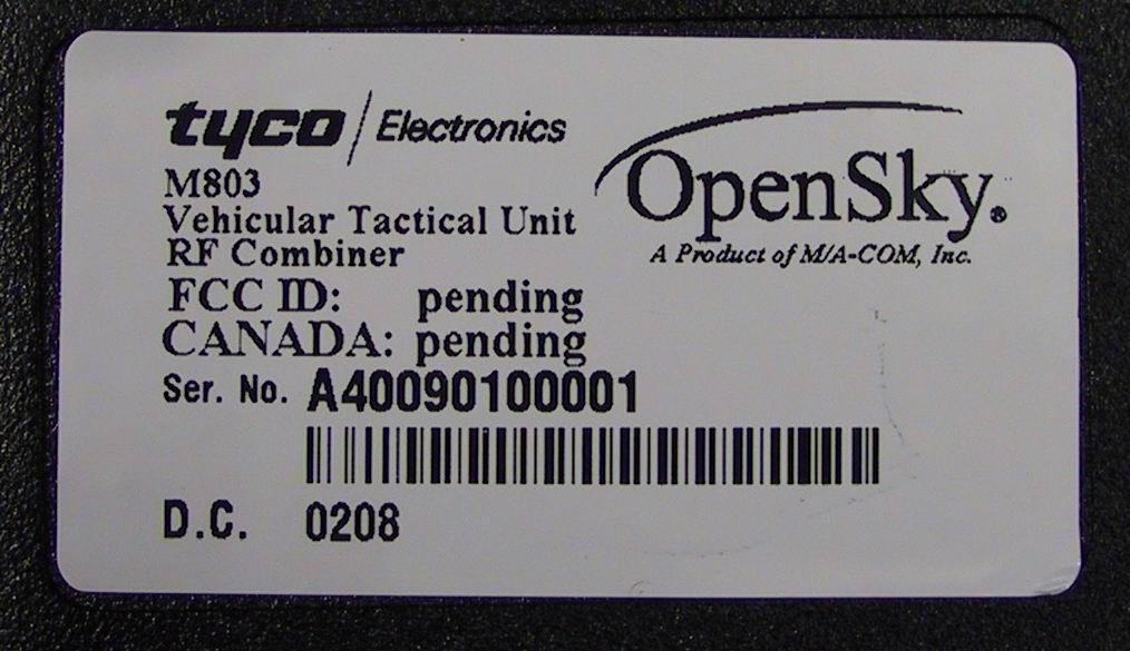
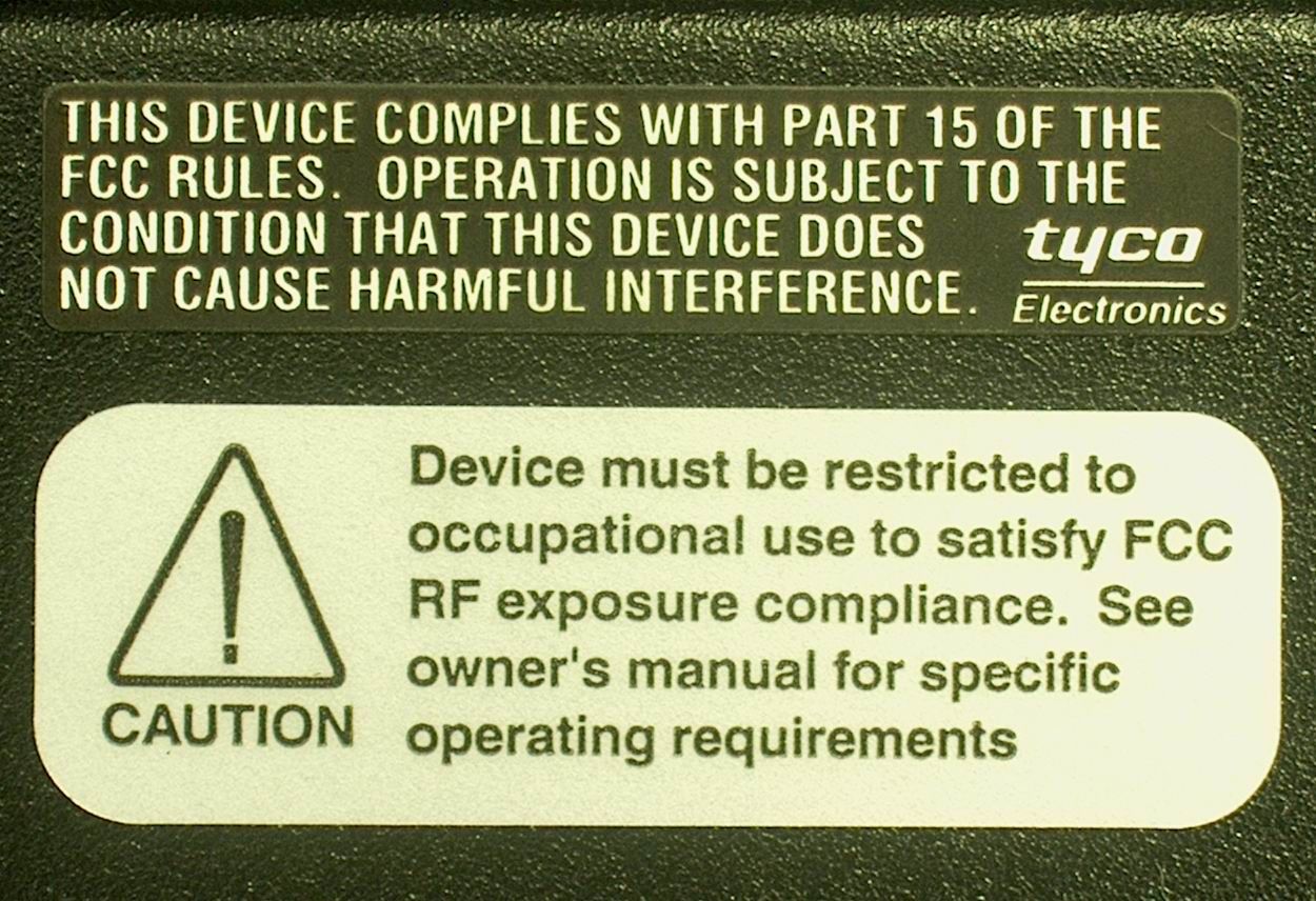
This exhibit contains the photographs of the FCC label and its location on the radio. They are: Figure 1 FCC Label Figure 2 Label located on the M-803 VRB Figure 3 Label located on the M-803 VTAC Figure 1 FCC Label Figure 2 Label located on the M-803 VRB FCC Label is located on the top back corner of the VRB Figure 3 Label located on the M-803 VTAC When the VTAC is assembled, the FCC Label is visible from the back of the VTAC
Internal Photos
This exhibit contains the photographs of the M-803 MRU Full Duplex Transceiver Board. They are: Figure 1 FD Top View#1 Figure 2 FD Top View #2 Figure 3 FD Bottom View #1 Figure 4 FD Bottom View #2 Figure 1 FD Top View#1 Figure 2 FD Top View #2 Figure 3 FD Bottom View #1 Fi Figure 4 FD Bottom View #2
Internal Photos
This exhibit contains the photographs of the M-803 MRU/VRB High Powered Amplifer Board. They are: Figure 1 HPA Top View#1 Figure 2 HPA Top View #2 Figure 3 HPA Bottom View #1 Figure 4 HPA Bottom View #2 Figure 1 HPA Top View#1 Figure 2 HPA Top View #2 Figure 3 HPA Bottom View #1 Fi Figure 4 HPA Bottom View #2
Internal Photos
This exhibit contains the photographs of the M-803 VTAC-RF Combiner Board. They are: Figure 1 RFC Top View#1 Figure 2 RFC Top View #2 Figure 3 RFC Bottom View Figure 1 RFC Top View#1 Figure 2 RFC Top View #2 Figure 3 RFC Bottom View
Internal Photos
This exhibit contains the photographs of the M-803 VTAC-VRB Transceiver Board. They are: Figure 1 VRB Top View#1 Figure 2 RRB Top View #2 Figure 3 VRB Bottom View #1 Figure 4 VRB Bottom View #2 Figure 1 VRB Top View#1 Figure 2 RRB Top View #2 Figure 3 VRB Bottom View #1 Fi Figure 4 VRB Bottom View #2
RF Exposure Info
10.0 RF Exposure FCC §2.1091, §2.1093 10.1Test Procedure The EUT was activated at full power, and connected to the five antennas that will be provided for use with it. Each antenna was placed at three different positions on a test vehicle, the center of the roof, the center of the trunk, and centered on the trunk at the back window, excepting the puck and transit style antennas, which were placed at the roof and center of the trunk. These are typical mounting points. A measurement antenna was connected to a spectrum analyzer, and peak readings of the field strength were taken at various test points outside and inside of the vehicle. Measurement antenna height and polarization were varied at each point to produce the worst-case value. Below are diagrams showing the transmit antenna mounting point and the corresponding test point locations and designations. The readings at the spectrum analyzer are in dBuV/m. The limits are expressed in mW/cm 2 . An equation that relates these two values is E = 20 LOG (1x10 6 (377*10*P) 1/2 ) where E is the measured voltage in dBuV/m, and P is the power density in mW/cm 2 . The factor 377 is the impedance of free space, a constant. The obtained power density can then be compared to the limits. The power density limit for uncontrolled exposure is f/1500, where f is the transmit frequency. The worst case limits are at the lowest transmit frequency, and the measured RF output power of the EUT at the antenna port was maximum at the lowest transmit frequency. Therefore the lowest transmit frequency of 806.0125 MHz was selected as the worst case frequency and the limit for Maximum Permissible Exposure (MPE) was determined to be 0.537 mW/cm 2 . The distance between the transmit antenna and the test points is measured, and compared to a calculated Minimum Safe Distance (MSD). The MSD is determined by taking the maximum power output at the antenna terminals and adding the gain of the transmit antenna to determine the Effective Isotropic Radiated Power (EIRP). The EIRP assumed to radiate spherically from the transmit antenna and the Minimum Safe Distance is the radius of a sphere large enough that the radiated power density at the surface is equal to the limits for Maximum Permissible Exposure (MPE). The following equation relates the EIRP (mW) of the trans mi tter a nd P ( mW/c m 2 ), the power density at radius r (cm): EIRP = P*4*Pi*r 2 VRM: EIRP 3d B = maximum radio output (42.5 dBm) + maximum antenna gain (3 dB) = 45.5 dBm FD FP RD RM RP F L R B FD FP RD RM RP F L R B FD FP RD RM RP F L R B F = Front FD = Front Driver Side RP = Rear Passenger Side L = Left FP = Front Passenger Side = Transmit Antenna R = Right RD = Rear Driver Side B = Back RM = Rear Middle Roof Mount Trunk @ Windo w Mount Trunk @ Cente r Mount EIRP 0d B = maximum radio output (42.5 dBm) + maximum antenna gain (0 dB) = 42.5 dBm VRB: EIRP 3d B = maximum radio output (41 dBm) + maximum antenna gain (3 dB) = 44 dBm EIRP 0d B = maximum radio output (41 dBm) + maximum antenna gain (0 dB) = 41 dBm Therefore, MSD 3d B = [(EIRP1 + EIRP2)/(4*Pi*P)] 1/2 = 95 cm MSD 0d B = [(EIRP1 + EIRP2)/(4*Pi*P)] 1/2 = 67 cm Roof Mounting on Test Vehicle Trunk @ Window Mounting on Test Vehicle Trunk @ Center Mounting on Test Vehicle 10.2Test Results Data fields in the for mat (low freque nc y da ta)/(high freque nc y data). Antenna Specialists ASPSA912M 3dB Gain Roof Mount Te s t Point Fie l d St re ngt h Reading (dB uV/m) Fie l d St re ngt h Reading (mW/cm 2 ) Total Fie ld Strength (mW/cm 2 ) MPE Limit (mW/cm 2 ) Te s t Point Distance (cm) MSD Limit (c m) Front140.11 / 139.360.027 / 0.0230.0500.537294.095 Back141.80 / 142.450.040 / 0.0470.0870.537203.095 Left156.25 / 146.060.112 / 0.1070.2190.53797.095 Right148.14 / 147.900.173 / 0.1640.3360.537110.095 Front Driver136.80 / 130.310.013 / 0.0030.0160.53755.095 Front Passenger135.11 / 131.260.009 / 0.0040.0120.53754.095 Rear Driver135.22 / 130.830.009 / 0.0030.0120.53755.095 Rear Middle132.02 / 129.100.004 / 0.0020.0060.53748.095 Rear Passenger135.80 / 135.570.010 / 0.0100.0200.53760.095 Antenna Specialists ASPSA912M 3dB Gain Trunk @ Window Mount Te s t Point Fie l d St re ngt h Reading (dB uV/m) Fie l d St re ngt h Reading (mW/cm 2 ) Total Fie ld Strength (mW/cm 2 ) MPE Limit (mW/cm 2 ) Te s t Point Distance (cm) MSD Limit (c m) Front136.48 / 135.810.012 / 0.0100.0220.537429.095 Back 151.23 / 150.690.352 / 0.3110.663 0.53773.095 Left147.81 / 147.630.160 / 0.1540.3140.537100.095 Right149.63 / 149.190.244 / 0.2200.4640.537100.095 Front Driver141.26 / 139.810.035 / 0.0250.0610.537165.095 Front Passenger143.13 / 139.300.055 / 0.0250.0770.537165.095 Rear Driver145.42 / 144.340.092 / 0.0720.1640.53785.095 Rear Middle144.51 / 143.300.075 / 0.0570.1320.53775.095 Rear Passenger145.11 / 143.570.086 / 0.0600.1460.53785.095 Antenna Specialists ASPSA912M 3dB Gain Trunk @ Center Mount Te s t Point Fie l d St re ngt h Reading (dB uV/m) Fie l d St re ngt h Reading (mW/cm 2 ) Total Fie ld Strength (mW/cm 2 ) MPE Limit (mW/cm 2 ) Te s t Point Distance (cm) MSD Limit (c m) Front135.30 / 134.950.009 / 0.0080.0170.537454.095 Back 153.02 / 152.080.532 / 0.4280.960 0.53747.095 Left147.21 / 147.830.140 / 0.1610.3000.537100.095 Right147.22 / 147.830.140 / 0.1610.3010.537100.095 Front Driver141.35 / 142.030.036 / 0.0420.0790.537185.095 Front Passenger142.72 / 142.760.050 / 0.0500.1000.537185.095 Rear Driver146.62 / 144.310.122 / 0.0720.1930.537105.095 Rear Middle144.85 / 145.040.081 / 0.0850.1660.537100.095 Rear Passenger145.78 / 144.470.100 / 0.0740.1750.537105.095 Antenna Specialists ASPA1850M 3dB Gain Roof Mount Te s t Point Fie l d St re ngt h Reading (dB uV/m) Fie l d St re ngt h Reading (mW/cm 2 ) Total Fie ld Strength (mW/cm 2 ) MPE Limit (mW/cm 2 ) Te s t Point Distance (cm) MSD Limit (c m) Front136.54 / 139.000.012 / 0.0210.0330.537294.095 Back139.99 / 142.310.026 / 0.0450.0720.537203.095 Le ft 149.58 / 150.660.241 / 0.3090.550 0.53797.095 Right147.71 / 149.820.157 / 0.2540.4110.537110.0…
Text truncated - open the document above for the full version.
Test Report
Low End of Band Transmit Channel, VRB, Emissions Mask G Low End of Band Transmit Channel, VRM, Emissions Mask G Middle of Band Transmit Channel, VRB, Emissions Mask G Middle of Band Transmit Channel, VRM, Emissions Mask G High End of Band Transmit Channel, VRB, Emissions Mask G High End of Band Transmit Channel, VRM, Emissions Mask G Low End of Band Transmit Channel, VRB, Emissions Mask H Low End of Band Transmit Channel, VRM, Emissions Mask H High End of Band Transmit Channel, VRB, Emissions Mask H High End of Band Transmit Channel, VRM, Emissions Mask H
Test Report
Low Channel Transmit, Emissions Mask G Mid Channel Transmit, Emissions Mask G High Channel Transmit, Emissions Mask G Low Channel Transmit, Emissions Mask H High Channel Transmit, Emissions Mask H
Test Report
FCC Part 90 Test Report for M/A-Com, Inc. on the M-803 Vehicular Tactical Unit Model: MAMROS0016 FCC ID: BV8M803VTAC Test Report #: 3019505 Date of Report: February 8, 2002 Project #: 3019505 Dates of Test: February 4-7, 2002 Total No of Pages Contained in thisReport: 22 + Data Sheets NVLAP Laboratory Code: 100270-0 Nicholas Abbondante, Test Engineer Robert Martin, Senior Technical Manager All services undertaken are subject to the following general policy: Reports are submitted for exclusive use of the client to whom they are addressed. Their significance is subject to the adequacy and representative character of the samples and to the comprehensiveness of the tests, examinations or surveys made. This report shall not be reproduced except in full, without written consent of Intertek Testing Services, NA Inc. This report must not be used to claim product endorsement by NVLAP, NIST nor any other agency of the U.S. Government. FCC Part 90 Certification • 70 Codman Hill Road Boxborough MA 01719 M/A-Com, Model No. MAMROS0016Date of Test: February 4-7, 2002 FCC ID: BV8M803VTAC Report # 30195052FCC Part 90 Table of Contents 1.0Summary of Tests................................................................................................................. 3 2.0General Description ............................................................................................................. 4 2.1Product Description.................................................................................................... 4 2.2Related Submittal(s) Grants........................................................................................ 4 2.3Test Facility.............................................................................................................. 5 2.4Test Equipment and Support Equipment...................................................................... 6 3.0RF Power Output................................................................................................................. 7 3.1Test Procedure........................................................................................................... 7 3.2Test Results............................................................................................................... 7 4.0Occupied Bandwidth, Bandwidth Limitation, Emission Masks............................................ 8 4.1Test Procedure........................................................................................................... 8 4.2Test Results............................................................................................................... 8 5.0Out-of-Band Emissions at Antenna Terminals ..................................................................... 9 5.1Test Procedure........................................................................................................... 9 5.2Test Results............................................................................................................... 9 6.0 Field Strength of Spurious Radiation.................................................................................. 10 6.1Test Procedure......................................................................................................... 10 6.2Test Results............................................................................................................. 11 7.0 Frequency Stability vs Temperature.................................................................................. 12 7.1Test Procedure......................................................................................................... 12 7.2Test Results............................................................................................................. 12 8.0 Frequency Stability vs Voltage.......................................................................................... 13 8.1Test Procedure......................................................................................................... 13 8.2Test Results............................................................................................................. 13 9.0Transient Frequency Behavior........................................................................................... 14 9.1Test Procedure......................................................................................................... 14 9.2Test Results............................................................................................................. 14 10.0 RF Exposure.................................................................................................................... 15 10.1 Test Procedure........................................................................................................ 15 10.2Test Results............................................................................................................. 18 • 70 Codman Hill Road Boxborough MA 01719 M/A-Com, Model No. MAMROS0016Date of Test: February 4-7, 2002 FCC ID: BV8M803VTAC Report # 30195053FCC Part 90 1.0Summary of Tests FCC ID: BV8M803VTAC Model No.: MAMROS0016 FCC RULEDESCRIPTION OF TESTRESULTSREPORT PAGE 2.1046RF Power OutputPassed8 2.1049, 90.209(b)(5), 90.210 Occupied Bandwidth, Bandwidth Limitation, Emission Masks Passed9 2.1051Out-of-Band Emissions at Antenna TerminalsPassed10 2.1053, 90.205, 90.635Field Strength of Spurious RadiationPassed12 2.1047Modulation CharacteristicsN/A-- 2.1055Frequency Stability vs. TemperaturePassed13 2.1055Frequency Stability vs. VoltagePassed14 2.914Transient Frequency BehaviorN/A15 2.1091, 2.1093RF ExposurePassed19 Test Engineer: Date: Nicholas Abbondante Senior Technical Manager: Date: Robert Martin • 70 Codman Hill Road Boxborough MA 01719 M/A-Com, Model No. MAMROS0016Date of Test: February 4-7, 2002 FCC ID: BV8M803VTAC Report # 30195054FCC Part 90 2.0General Description 2.1Product Description The M-803 Vehicular Tactical (VTAC) Unit is a versatile voice and da…
Text truncated - open the document above for the full version.
Test Report
Summary of Testing, Conducted Spurious Emissions at Low and Mid Power Levels, 5/6/02 Results: Passed, Low (25 dBm) and Mid (35 dBm) power settings with Low, Mid, and High transmit frequencies. See test report for high power test data. EUT: M-803 Vehicular Tactical (VTAC) Unit Model: MAMROS16 Subassembly:Serial Numbers: VRMA40071000064 VRBA4007000038F RF CombinerA4009010005A Control HeadA4000A100074 Support Equipment DescriptionManufacturerModel NumberSerial Number Laptop Computer Compaq ArmadaCompaq7800 6300/T/8000/V/M/17919CB630126 FanElectrixN619N/L DC Power SupplyHewlett Packard6652A910-510 Cables QuantityTypeLength (m)ShieldingFerriteConnector Type 2Seria l Cable4NoNoMetal w/360 1Microphone Cable1NoNoPlastic 4DC Power Cable4NoNoPlastic 1AC Power Cable2NoNoPlastic Test Equipment DescriptionManufacturerModel NumberSerial NumberCal Due Date Cable, SMA – SMA <18 GHzSucoflex104PECBLSHF1034/01/03 Spectrum AnalyzerAgilentE7405AUS4024020511/02/02 30 dB AttenuatorWeinschel Corporation47-30-34BD43278/24/02 Procedure: The antenna was disconnected from the transmitter and a spectrum analyzer was connected to the transmitter RF output through sufficient attenuation to prevent overloading of the analyzer. The resolution bandwidth of the spectrum analyzer was set up to 300 Hz in the 100 kHz span around the transmit frequency, and the spectrum of the transmitting signal was recorded. The resolution bandwidth of the spectrum analyzer was set at 100 kHz below 1 GHz. Above 1 GHz the bandwidth was set to 1 MHz. Sufficient scans were taken to show the out-of-band emissions, if any, up to 10th harmonic. Low Power is the lowest power the device will be programmed to operate at, 25 dBm, and mid power was selected to be 35 dBm. Requirement: The power of emissions must be attenuated below the power of the unmodulated carrier (P) on any frequency removed from the assigned frequency by more than 250 percent of the authorized bandwidth at least (43 + 10 log P) dB, which is –13 dBm or 94 dBuV. The transmit waveforms must meet the emissions masks G and H as outlined in 90.210. 30 dB of attenuation was used with 2.3 dB loss in the cable, so a display line was placed at 61.7 to reflect the limit beyond 250% of the authorized bandwidth. Low Power Low Transmit Channel 30 MHz – 1 GHz Low Power Low Transmit Channel 1 GHz – 5.5 GHz Low Power Low Transmit Channel 5.5 GHz – 10 GHz Low Power Mid Transmit Channel 30 MHz – 1 GHz Low Power Mid Transmit Channel 1 GHz – 5.5 GHz Low Power Low Transmit Channel 5.5 GHz – 10 GHz Low Power High Transmit Channel 30 MHz – 1 GHz Low Power High Transmit Channel 1 GHz – 5.5 GHz Low Power High Transmit Channel 5.5 GHz – 10 GHz Low Power Low Transmit Channel Mask G VRM Low Power Mid Transmit Channel Mask G VRM Low Power High Transmit Channel Mask G VRM Low Power Low Transmit Channel Mask H VRM Low Power Hig…
Text truncated - open the document above for the full version.
Contact Information
Applicant
Thomas Camper, Jr.(Regulatory Manager)
Technical Contact
M/A Com Inc.Bill Delaney
[email protected]9784425321
70 Codman Hill Road · Lowell, Massachusetts · United States
Non-Technical Contact
M/A Com Inc.Andy Moysenko
[email protected]9784424762
Test Firm
Intertek Testing Services NA Inc.Roland Gubisch
Technical Specifications
| # | Rule Parts | Frequency Range | Power Output | Emission | Tolerance |
|---|---|---|---|---|---|
| 4 | 9 | 851 MHz - 869 MHz | 17 W | 15K8F7E | 1.5 ppm |
Other Applications from Harris Corporation
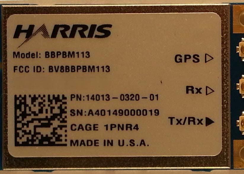
BV8BBPBM113
Apr 11, 2013Wireless Licensed Module
Equipment Class
TNB - Licensed Non-Broadcast Station Transmitter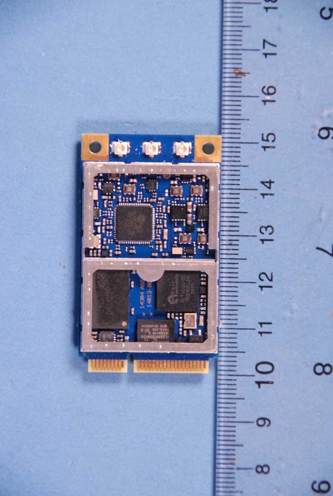
BV8BBPBM100
Feb 09, 2012700 MHz LTE Wireless Module
Equipment Class
TNB - Licensed Non-Broadcast Station Transmitter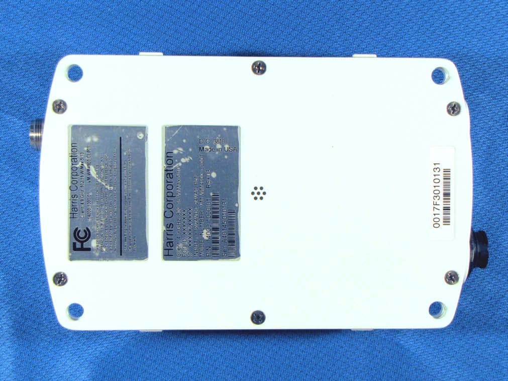
BV8WM4900CL
Nov 21, 2010Client 4.9 GHz 802.16 VBB 5/10
Equipment Class
TNB - Licensed Non-Broadcast Station Transmitter
BV8VIDA-BB-CL
Apr 11, 2007VIDA Broadband High Power Client
Equipment Class
TNB - Licensed Non-Broadcast Station Transmitter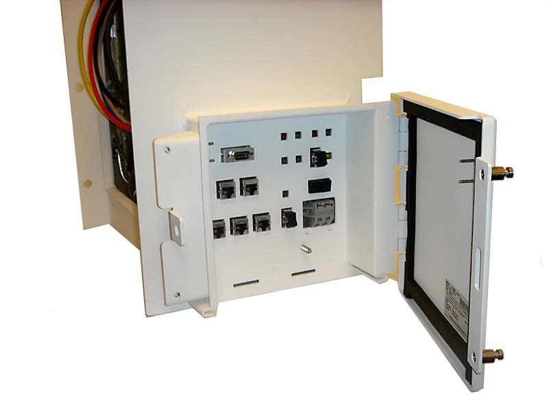
BV8CS900
Apr 08, 2007OpenSky 900 MHz Cell Site
Equipment Class
TNB - Licensed Non-Broadcast Station Transmitter