BV8MCS800A025OPENSKY CELL SITE BASE STATION, MCS-0001
Harris Corporation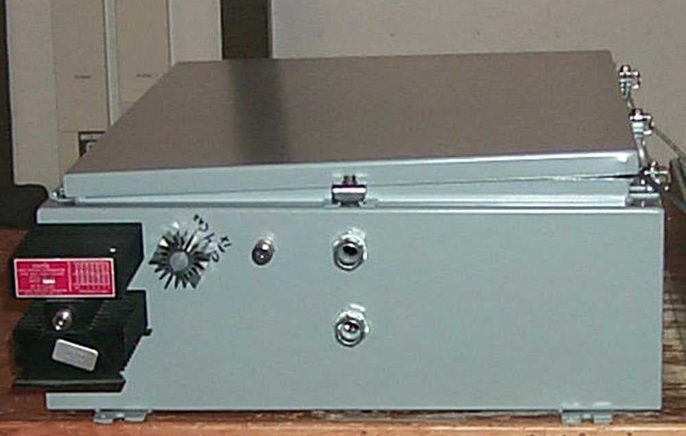
Click to zoom
Application Details
- Equipment Class
- TNB - Licensed Non-Broadcast Station Transmitter
- Date of Grant
- Apr 27, 2000
- Application Purpose
- Original Equipment
- Date of Application
- Feb 10, 2000
- Equipment Note
- OPENSKY CELL SITE BASE STATION, MCS-0001
- Frequency Range
- 851.00000000 - 869.00000000
- Company
- Harris Corporation
- Country
- United States
Documents & Files
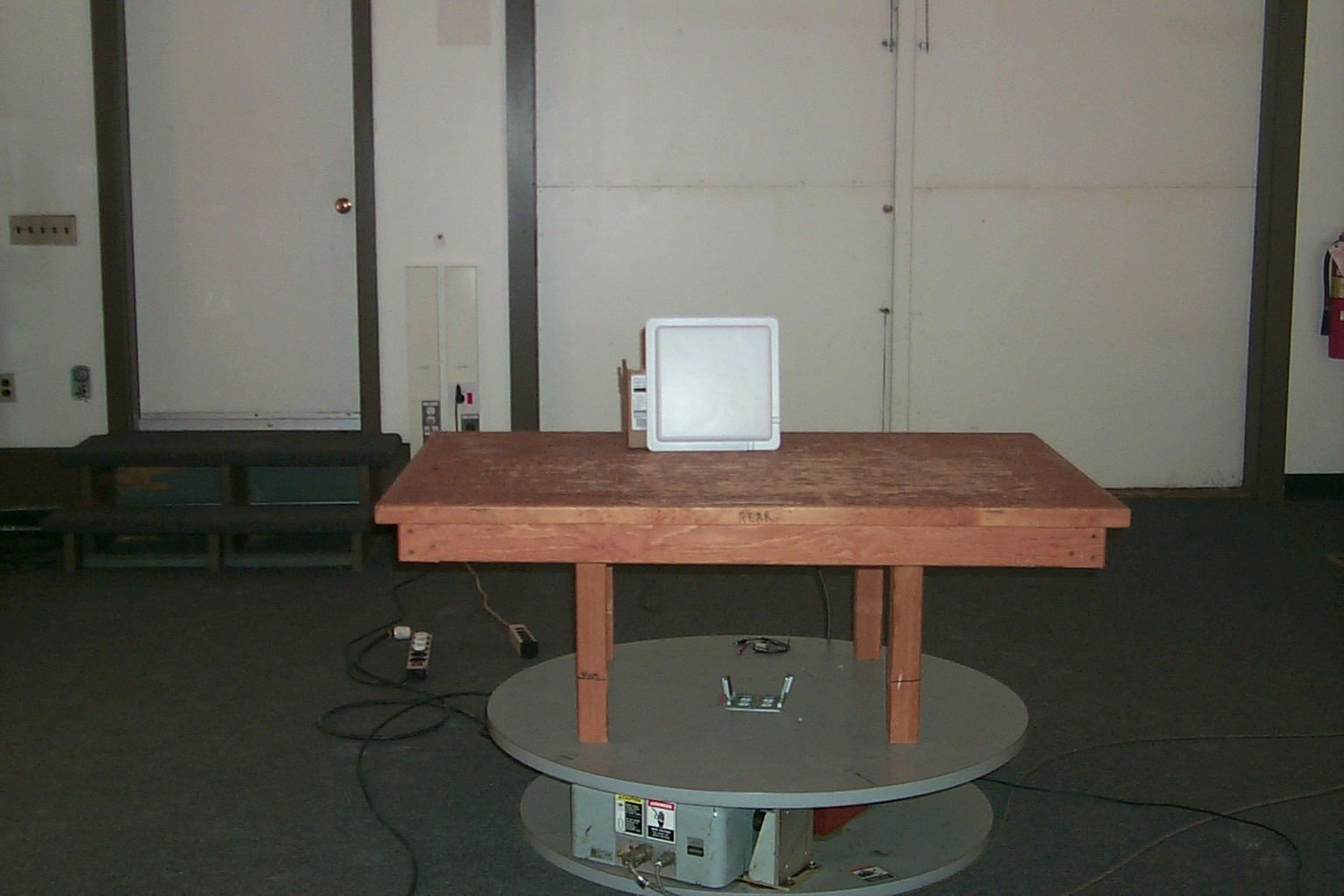
Document Text
Text extracted from the exhibit documents filed with the FCC. Open a document above to read the original.
Cover Letter(s)
January 7, 2000 Federal Communications Commission Washington, DC 20554 Subject:M/A-COM Submission for FCC Certification/Type Acceptance Reference:M/A-COM’s OpenSky TM Cell Site To Whom It May Concern: M/A-COM, Inc. hereby requests that certain sections, exhibits and the like, to our attached submission be treated by the FCC as confidential information. The sections that require confidentiality is for the most part all of the Section entitled Block Diagrams and Schematics and includes the following technical information: • Detailed Theory of Operation • ADX Amplifier/Duplexer Schematic, Drawing No. HE00620 • ADX Amplifier/Duplexer Schematic, Drawing No. HE00558 • BSC Schematic, Drawing No. HE00552 • BSX Schematic, Drawing No. HE00536 • ECP Train Radio Schematic, Drawing No. CTC-00690 The above technical information which is explicitly characterized in our submission, describes in detail how our product is built and its theory of operation. This level of technical information, if disclosed outside the FCC, would cause irreparable harm to M/A-COM from a competitive standpoint. Therefore, we respectfully request that the technical information listed herein and fully described in our submission attached hereto be treated as confidential information and not be disclosed outside of the FCC. Sincerely, Noreen Kealey Contracts Administrator Enclosures January 7, 2000 Industry Canada Subject:M/A-COM Submission for Industry Canada Certification/Type Acceptance Reference:M/A-COM’s OpenSky TM Cell Site To Whom It May Concern: M/A-COM, Inc. hereby requests that certain sections, exhibits and the like, to our attached submission be treated by Industry Canada as confidential information. The sections that require confidentiality is for the most part all of the Section entitled Block Diagrams and Schematics and includes the following technical information: • Detailed Theory of Operation • ADX Amplifier/Duplexer Schematic, Drawing No. HE00620 • ADX Amplifier/Duplexer Schematic, Drawing No. HE00558 • BSC Schematic, Drawing No. HE00552 • BSX Schematic, Drawing No. HE00536 • ECP Train Radio Schematic, Drawing No. CTC-00690 The above technical information which is explicitly characterized in our submission, describes in detail how our product is built and its theory of operation. This level of technical information, if disclosed outside Industry Canada, would cause irreparable harm to M/A-COM from a competitive standpoint. Therefore, we respectfully request that the technical information listed herein and fully described in our submission attached hereto be treated as confidential information and not be disclosed outside of Industry Canada. Sincerely, Noreen Kealey Contracts Administrator Enclosures
Cover Letter(s)
March 17, 2000 Federal Communications Commission 7435 Oakland Mills Road Columbia, MD 21046 REFERENCE: BV8MCS800A025 (EA96755 and EA96774) To Whom It May Concern: The above mentioned composite certifications were submitted on February 11 and 14, 2000. I would like to request that the following adminsitrative changes be made to these submittals as follows: BV8MCS800A025 (EA96755): Composite Submittal Part 15.247 / Part 90 1.On the 731 Form (item 10) please change the equipment code to TNB (not GVH as listed). 2.Please change the description on the Test Report and the FCC submittal to read: FCC Part 15.247 (not FCC Part 15.2439 as stated). BV8MCS800A025 (EA96774): Composite Submittal Part 15.247 / Part 90 1.On the 731 Form (item 10), please change the equipment code to DSS (not DXX as listed). 2.Please change the description on the Test Report and in the FCC submittal to read: FCC Part 15.247 (not 15.2439 as stated.) If you have any questions regarding these changes, please call me or email me. Thank you for your prompt attention to this matter. Sincerely, Patty Terilli Chomerics Test Services Coordinator 77 Dragon Court Woburn, MA 01888 781-939-4158 FAX: 781-935-2758
Cover Letter(s)
March 20, 2000 Mr. Frank Coperich Federal Communications Commission Equipment Authorization Division 7435 Oakland Mills Road Columbia, Maryland 21046 FCC ID: BV8MCS800A025 FCC CORRESPONDENCE REFERENCE: 12838 Dear George: In response to your questions/comments, please note the following: 1. Carson’s rule is most accurate for sinusoidal modulation or where the baseband has a clearly defined bandwidth. The baseband of the OpenSky digital signal has a gradual roll- off from DC until a null at 9600 Hz. Selecting 9600 Hz as m would calculate a bandwidth much wider than the actual FSK signal. Using the 3 dB point one obtains an m of 4800 Hz. The signal deviation (d) is 4000 Hz. Assuming k = 1 the following bandwidth is calculated. Using this rule m = 4800, d = 4000, k=1 =>>17600 Hz bandwidth This bandwidth is also much wider than the actual signal. To match the 99% bandwidth number, 11.3 kHz previously reported k can be set to 0.2125. The 99% bandwidth number was previously reported due to the fact that it seemed more applicable and appropriate to this digital waveform. 2. Understood. Future occupied bandwidth tests will be done at a narrower Resolution Bandwidth (RBW). If my comments need further clarification or you require additional information, please do not hesitate to call me at (781) 939-4375. Sincerely, David C. Inman CTS Manager (781) 939-4375 Phone (781) 935-2758 Fax [email protected] E-mail FCC – MACOM3
ID Label/Location Info
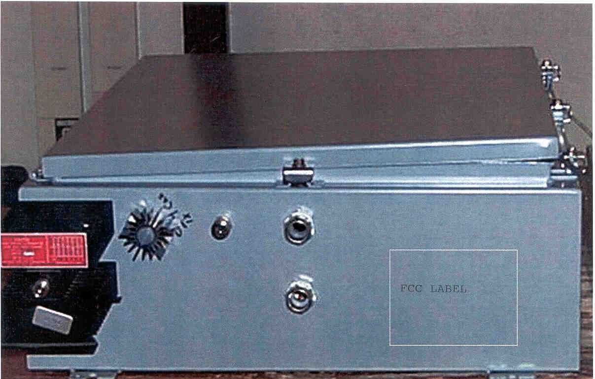
Proposed FCC Label FCC ID: BV8MCS800A025 M/A-COM a division of AMP Incorporated Made in USA This device complies with Part 15 of the FCC Rules. Operation is subject to the condition that this device does not cause harmful interference.
Parts List/Tune Up Info
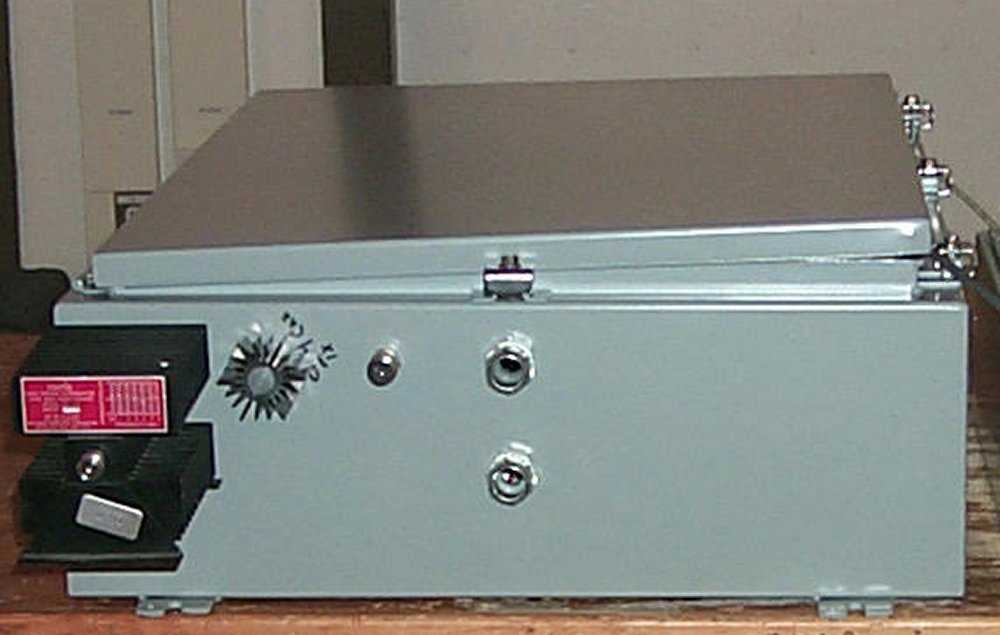
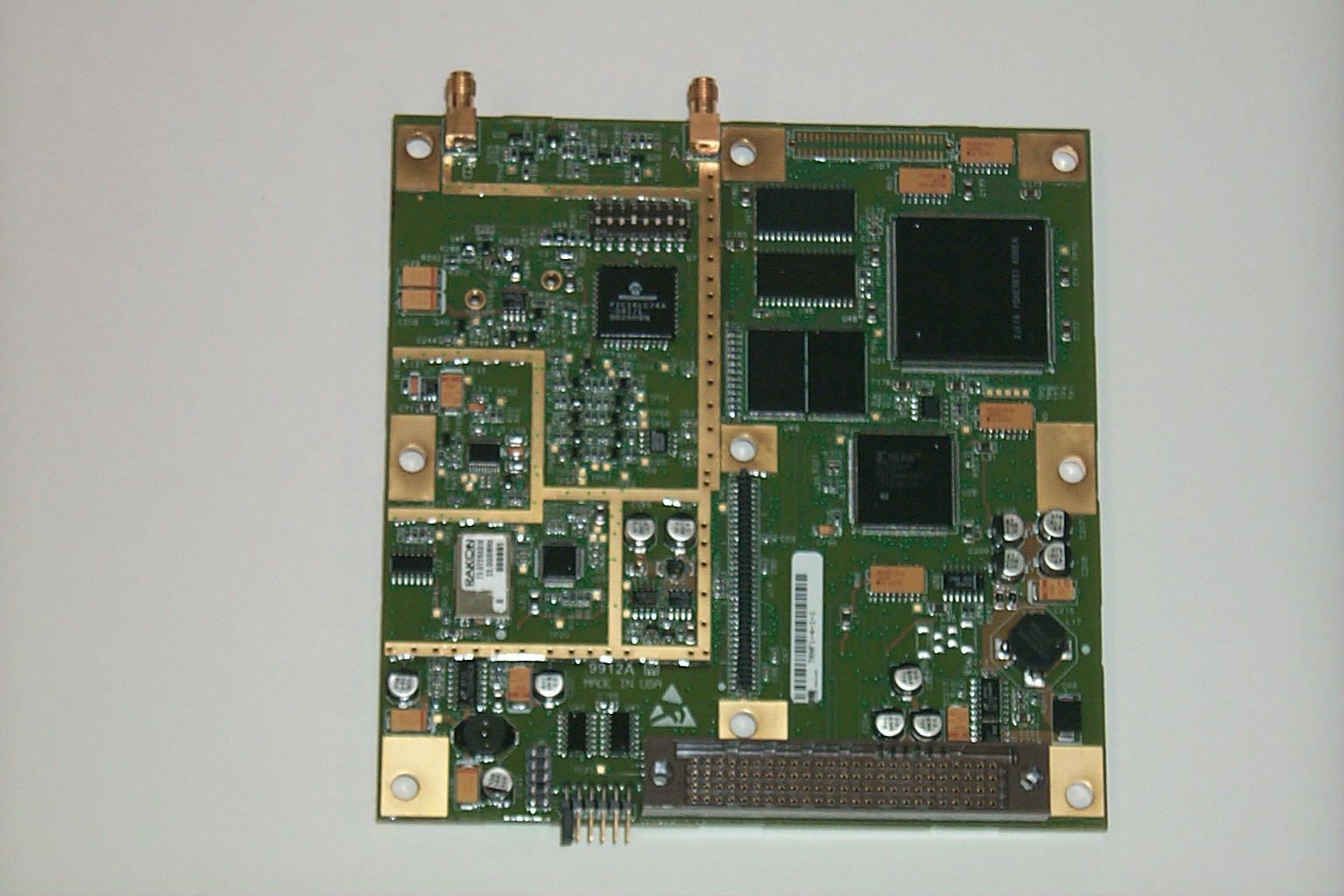
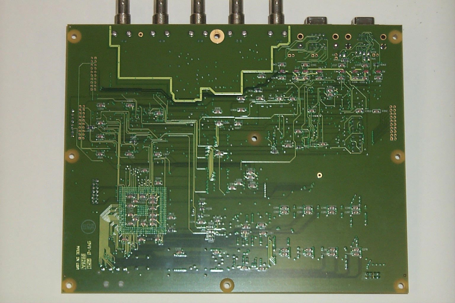
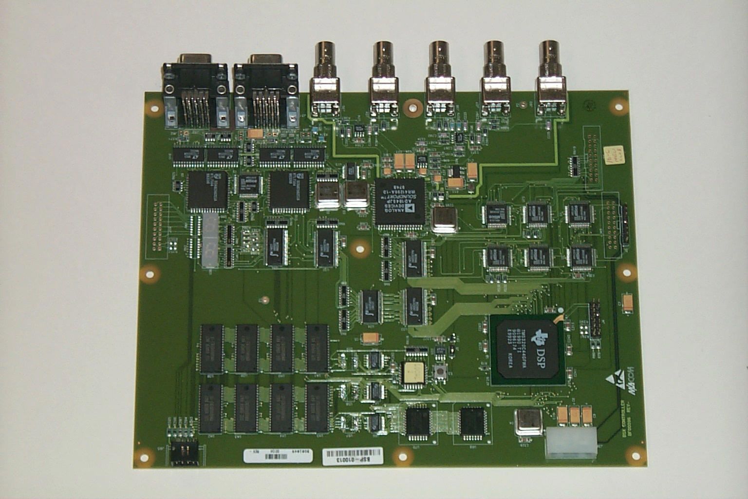
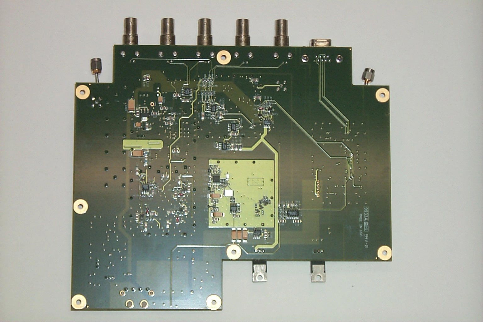
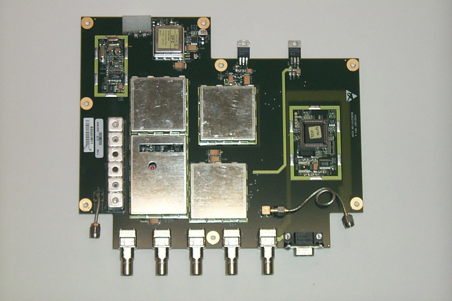
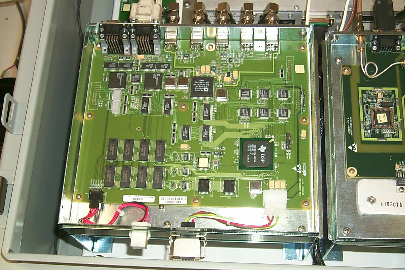
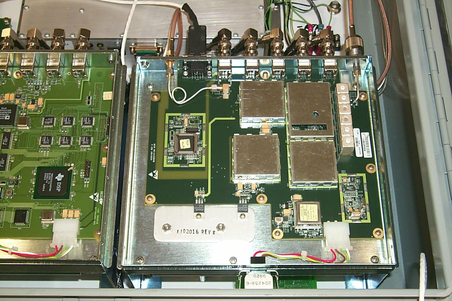
Summary of Key Features The OpenSky Base Station employs a modular design approach. All five functional elements— the BSC, BSX, ISM, AD and HPA--are self-contained within their respective housings. This modular approach offers customers the benefit of ease of service. Replacement of any of the five main functional components can be accomplished in minutes. All five functional elements of the base station are separately mounted within the cell site enclosure, making module substitution a simple matter of a few mounting screws and a couple of cables. This cell site enclosure also includes the required DC power supply. The division of the five main functional elements and the power supply into separate metal enclosures minimizes spurious emissions and component interaction. BSC - Base Station Controller: The BSC is the processing engine of the base station. Utilizing software exclusively, the BSC implements all base station network and digital signal-processing functions. These functions include the Physical Layer (PHY), Medium Access Control (MAC), Mobile Data Link Protocol (MDLP), Radio Resource Management (RRM), Network Management (NMS) and Secondary Registration. BSX - Base Station Transceiver: The BSX consists of a transmitter and receiver section, each of which implements the corresponding RF transmit and receive functions. As seen in the accompanying figure, during transmission, the BSC generates an In- Phase/Quadrature (IQ) baseband signal that is routed to the baseband input of the BSX transmitter. The BSX transmitter converts this baseband signal to a RF output signal, at the selected SMR channel frequency. The nominal output power of this output signal is 0 dBm when measured into a 50 ⋅ load. The receiver section of the BSX essentially reverses the transmit process. The antenna routes the desired receive signal to the RF input of the BSX. The receiver section converts the signal to a baseband I/Q signal that is routed to the BSC for further processing. A DC reference signal is also provided by the BSC to the BSX to provide a common reference for both the receive and transmit I/Q baseband signals. ISM – Industrial, Scientific and Medical Wireless Modem: The ISM is a wireless modem that operates in the 2.4 GHz unlicensed frequency band. It serves as the interconnection between the OpenSky Cell Site Base Station and the OpenSky network. The use of the ISM eliminates the need for a wireline connection to the cell site and, therefore, the cost of providing a leased line. Eliminated also by the use of the ISM, is the need to route telephone cable through rugged terrain where cell sites are typically deployed. The ISM connects directly to the network port of the DCX though a RS-232 serial connection. The ISM also requires two antennas for diversity to improve the error rate over the wireless link. PLNA – Preselector/Low Noise Amplifier: The PLNA serves two functions. First the PLNA provides filtering for the transmit path. Outbound transmit signals are input to the PLNA through the TxIn connector and then fed through the transmit filter to attenuate unwanted spectral components. The second function provided by the PLNA is used to processing received signals. Inbound receive signals are first shaped by the PLNA’s preselection filter and then amplified by the LNA to improve receive sensitivity. Both incoming receive and outgoing transmit signals are served by a common antenna port. HPA - High Power Amplifier: The HPA produces the high power transmit signal routed to the TxIn port of the PLNA. To generate this transmit signal, the HPA amplifies the nominal 0 dBm RF input provided by the BSX, to generate a maximum output power of 25 Watts. The HPA also includes an RS-485 communications port that provides control, monitoring, and alarm generation. The HPA’s output power is controllable via this RS-485 connection from the BSC. Using this serial connection the BSC can adjust the output power of the HPA from 1 to 25 Watts. The HPA generates alarms in the case of excessive reflected power or input power, low power output and over-temperature alarms. These alarms are reported to the BSC and subsequently relayed through the NMS interface across the network port. Signal input power above 6 dBm causes the HPA to generate an input overdrive alarm and de- key the HPA output. Input signal levels below –10 dBm may prevent the HPA from generating full output power. This condition generates a power leveling control loop alarm, which de-keys the HPA. As described previously, the HPA provides a programmable 1 to 25 watt RF output signal into a 50⋅ load. Output protection insures no damage to the HPA from any mismatch condition. However, a programmable threshold on reflected power would normally de-key the HPA under mismatch conditions. DC Power Supply The DC power supply is an enclosure-mounted DC/DC converter that provides electrical power to devices requiring +12 VDC within the cell site base station. This 50- Watt power supply converts the +24 VDC supplied to the cell site to +12 VDC. The HPA and PLNA are supplied directly from the +24 VDC input, not via this supply.
Test Report
TEST SERVICES EMC EVALUATION OF THE M/A-COM OPENSKY CELL SITE BASE STATION MODEL MCS-0001 IN ACCORDANCE WITH THE FCC PART 90 CERTIFICATION AND FCC PART 15 SUBPART C CERTIFICATION Prepared For:M/A-COM 1011 PAWTUCKET BOULEVARD POST OFFICE BOX 3295 LOWELL, MASSACHUSETTS 01854 ATTENTION: DENNIS MARTINEZ Prepared By:ROBERT FOSTER CHOMERICS TEST SERVICES 77 DRAGON COURT WOBURN, MASSACHUSETTS 01888 Date:FEBRUARY 10, 2000 Test Report Number:EMI2453.US.00 Test Technician or Engineer: CTS Approved Signatory: This report shall not be reproduced except in full without the written approval of Chomerics Test Services. TEST SERVICES Document #: EMI2453.US.00 Date: February 10, 2000 Page 2 of 64 TABLE OF CONTENTS 1.0General 1.1Introduction 1.1.1Purpose 1.1.2Requirements 1.2Administrative Data 1.2.1Test Facility 1.2.2Equipment Calibration 1.2.3Test Personnel 1.3Test Set-up 1.3.1Test Site Matrix 1.3.2Test Site Descriptions 1.3.3Equipment Under Test 2.0Test Summary 2.1 Summary of Recommendations 3.0Tests Performed 3.1Output Power 3.1.1Equipment Used 3.1.2Test Conditions 3.1.3Test Method 3.1.4Results 3.2Occupied Bandwidth “SMR” 3.2.1Equipment Used 3.2.2Test Conditions 3.2.3Test Method 3.2.4Results 3.3Emission Mask and Spurious Emissions at Antenna Terminals “SMR’ 3.3.1Equipment Used 3.3.2Test Conditions 3.3.3Test Method 3.3.4Results 3.4Channel Spacing/Bandwidth “SMR” 3.4.1Equipment Used 3.4.2Test Conditions 3.4.3Test Method 3.4.4Results TEST SERVICES Document #: EMI2453.US.00 Date: February 10, 2000 Page 3 of 64 TABLE OF CONTENTS (continued) 3.5Field Strength of Spurious Radiation “SMR” 3.5.1Equipment Used 3.5.2Test Conditions 3.5.3Test Method 3.5.4Results 3.6 Modulation Characteristics 3.7Frequency Stability “SMR” 3.7.1Equipment Used 3.7.2Test Conditions 3.7.3Test Method 3.7.4Results 3.8Radiated Emissions SMR Receiver 3.8.1Equipment Used 3.8.2Test Conditions 3.8.3Test Method 3.8.4Results 3.9Conducted Emissions Full System 3.9.1Equipment Used 3.9.2Test Conditions 3.9.3Test Method 3.9.4Result 3.10Radiated Field Strength of F o and Harmonics of 2.4GHz Transmitter 3.10.1Equipment Used 3.10.2Test Conditions 3.10.3Test Method 3.10.4 Results 3.11Radiated Emissions 2.4GHz Receiver 3.11.1Equipment Used 3.11.2Test Conditions 3.11.3Test Method 3.11.4Results 4.0Appendix Appendix A:Test Data Appendix B:Set-Up Photographs Appendix C:Customer Supplied Modulation Characteristics Appendix D:Customer Supplied Equipment Description TEST SERVICES Document #: EMI2453.US.00 Date: February 10, 2000 Page 4 of 64 LIST OF DEFINITIONS/ABBREVIATIONS ACAlternating Current BBBroadband BWBandwidth cmCentimeter C.P.U.Calibrate Prior to Use dBDecibel DCDirect Current EMCElectromagnetic Compatibility EMIElectromagnetic Interference ERElectric Radiation EUTEquipment Under Test GHzGigahertz HzHertz I-faceInterface kHzKilohertz mMeter MHzMegahertz mmMillimeter mSMillisecond mVMillivolt MRMagnetic Radiation NBNarrowband N.C.R.No Calibration Required PLCPower Line Conduction PPSPulses Per Second uFMicrofarad uHMicrohenry uSMicrosecond uVMicrovolt U.W.C.Use With Calibrated Equipment TEST SERVICES Document #: EMI2453.US.00 Date: February 10, 2000 Page 5 of 64 1.0GENERAL 1.1Introduction 1.1.1Purpose The purpose of this report is to document the performance of the M/A-Com OpenSky Cell Site Base Station during a variety of radio-performance tests and record the test requirements and procedures used. At the request of M/A-Com, the tests were performed by Chomerics Test Service (CTS) of Woburn, Massachusetts. The assessment will determine the compliance or non-compliance to the requirements set by FCC Part 90 and Part 2. No representative from M/A-Com was present for testing. Testing was performed during the period of December 7, 1999 to January 21, 2000 under purchase order number 252221. 1.1.2Requirements The requirements for the sequence of tests performed on the M/A-Com OpenSky Cell Site Base Station are as follows: Output Power The RF output of the OpenSky Cell Site Base Station must be within ±1dB of the manufacturer’s rated output. Please note: This is not a FCC requirement but used for information purposes only. Occupied Bandwidth FCC Part 2.989 The Occupied Bandwidth is the frequency bandwidth such that, below its lower and above its upper frequency limits, the means power radiated are each equal to 0.5% of the total mean power radiated by a given emission. TEST SERVICES Document #: EMI2453.US.00 Date: February 10, 2000 Page 6 of 64 Emission Mask and Spurious Emissions at Antenna Terminals FCC Part 90.210 and Part 2.991 Mask B The following emission mask shall be followed. The power of any emission must be below the unmodulated carrier power (P) as follows: 1.On any frequency removed from the assigned frequency by more than 50%, but not more than 100% of the authorized bandwidth: At least 25dB. 2.On any frequency removed from the assigned frequency by more than 100%, but not more than 250% of the authorized bandwidth: At least 35dB. 3.On any frequency removed from the assigned frequency by more than 250% of the authorized bandwidth: At least 43 + 10 Log (P). Mask G The following emission mask shall be followed. The power of any emission must be below the unmodulated carrier power (P) as follows: 1. On any frequency removed from the center of the authorized bandwidth by a displacement frequency (fd in kHz) of more than 5kHz but not more than 10kHz: At least 83 log (fd/5) dB. 2.On any frequency removed from the center of the authorized bandwidth by a displacement frequency (fd in kHz) of more than 10kHz, but no more than 250% of the authorized bandwidth: At least 116 log (fd/6.1) dB or 50 + 10 log(P) dB or 70dB, whichever is the lesser attenuation. 3.On any frequency removed from the center of the authorized bandwidth by more than 250% of the authorized bandwidth: At least 43 + 10 Log (P) dB. TEST SERVICES Document #: EMI2453.US.00 Date: February 10, 2000 Page 7 of 64 Mask H The following emission mask shall be followed. The power of any emissi…
Text truncated - open the document above for the full version.
Contact Information
Applicant
Thomas Camper, Jr.(Regulatory Manager)
Technical Contact
CHOMERICS TEST SERVICESPATRICIA L TERILLI
[email protected]781-939-4158
77 DRAGON COURT · WOBURN, Massachusetts · United States
Non-Technical Contact
CHOMERICS TEST SERVICESPATRICIA L TERILLI
[email protected]781-939-4158
Test Firm
Chomerics Test ServicesDavid Inman
Technical Specifications
| # | Rule Parts | Frequency Range | Power Output | Emission | Tolerance |
|---|---|---|---|---|---|
| 1 | 90 | 851 MHz - 869 MHz | 25 W | 11K3F1D | 0.1000000000 ppm |
Other Applications from Harris Corporation
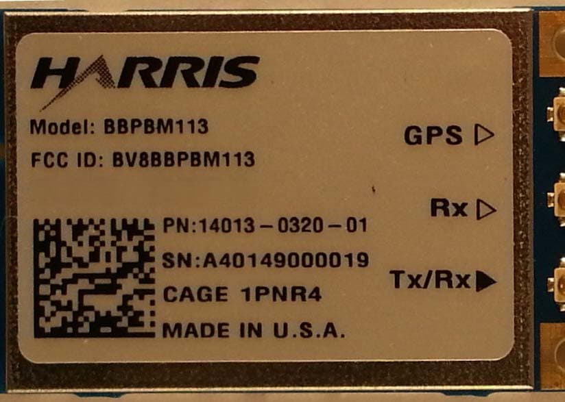
BV8BBPBM113
Apr 11, 2013Wireless Licensed Module
Equipment Class
TNB - Licensed Non-Broadcast Station Transmitter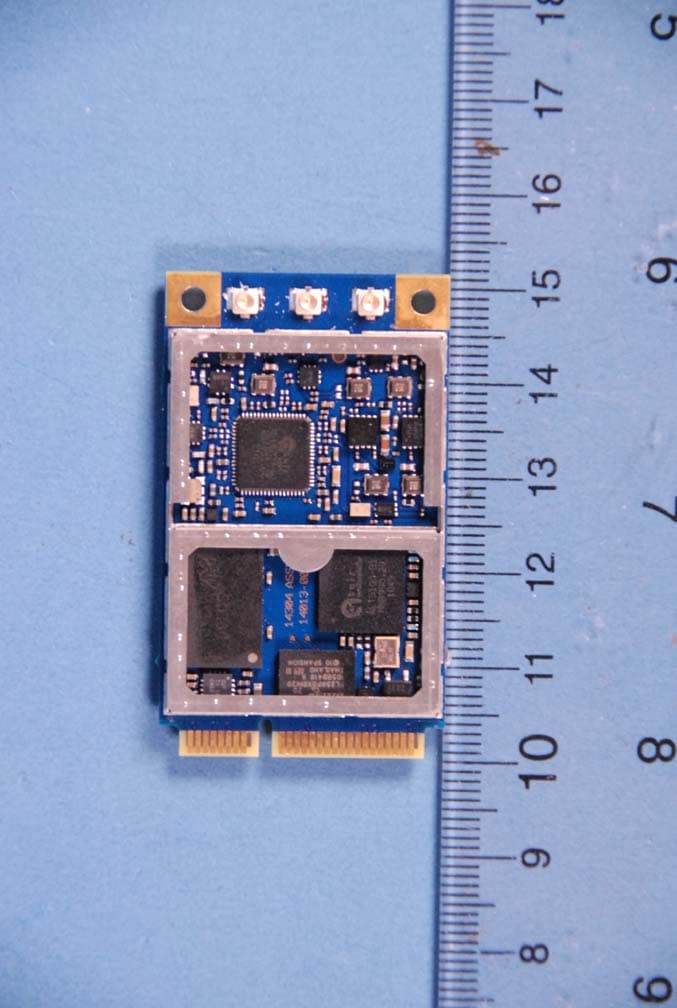
BV8BBPBM100
Feb 09, 2012700 MHz LTE Wireless Module
Equipment Class
TNB - Licensed Non-Broadcast Station Transmitter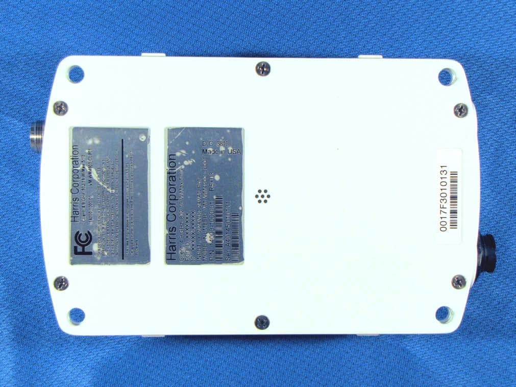
BV8WM4900CL
Nov 21, 2010Client 4.9 GHz 802.16 VBB 5/10
Equipment Class
TNB - Licensed Non-Broadcast Station Transmitter
BV8VIDA-BB-CL
Apr 11, 2007VIDA Broadband High Power Client
Equipment Class
TNB - Licensed Non-Broadcast Station Transmitter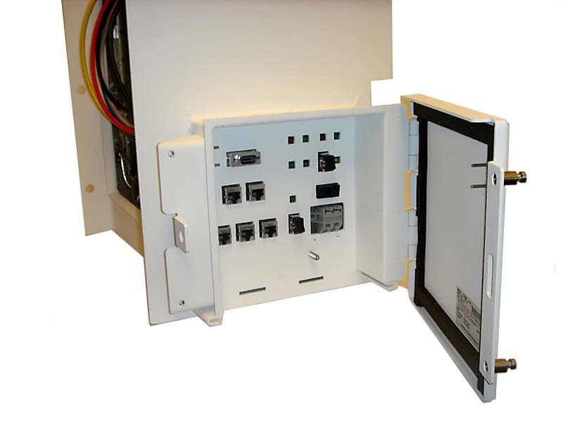
BV8CS900
Apr 08, 2007OpenSky 900 MHz Cell Site
Equipment Class
TNB - Licensed Non-Broadcast Station Transmitter