BV8P-801TP-801T VOICE TERMINAL RADIO
Harris Corporation
Click to zoom
Application Details
- Equipment Class
- TNB - Licensed Non-Broadcast Station Transmitter
- Date of Grant
- Feb 08, 2001
- Application Purpose
- Original Equipment
- Date of Application
- Apr 24, 2000
- Equipment Note
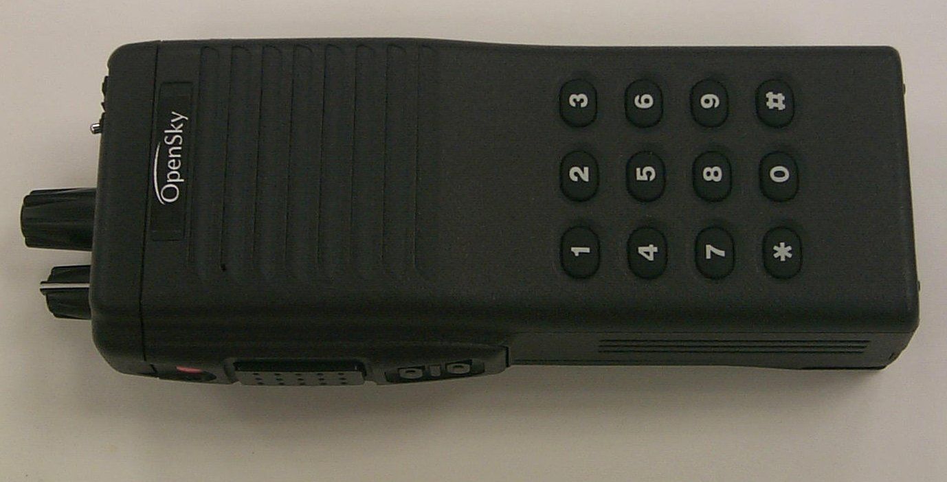
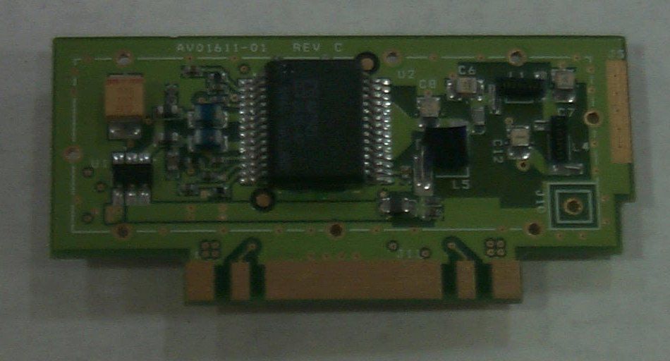
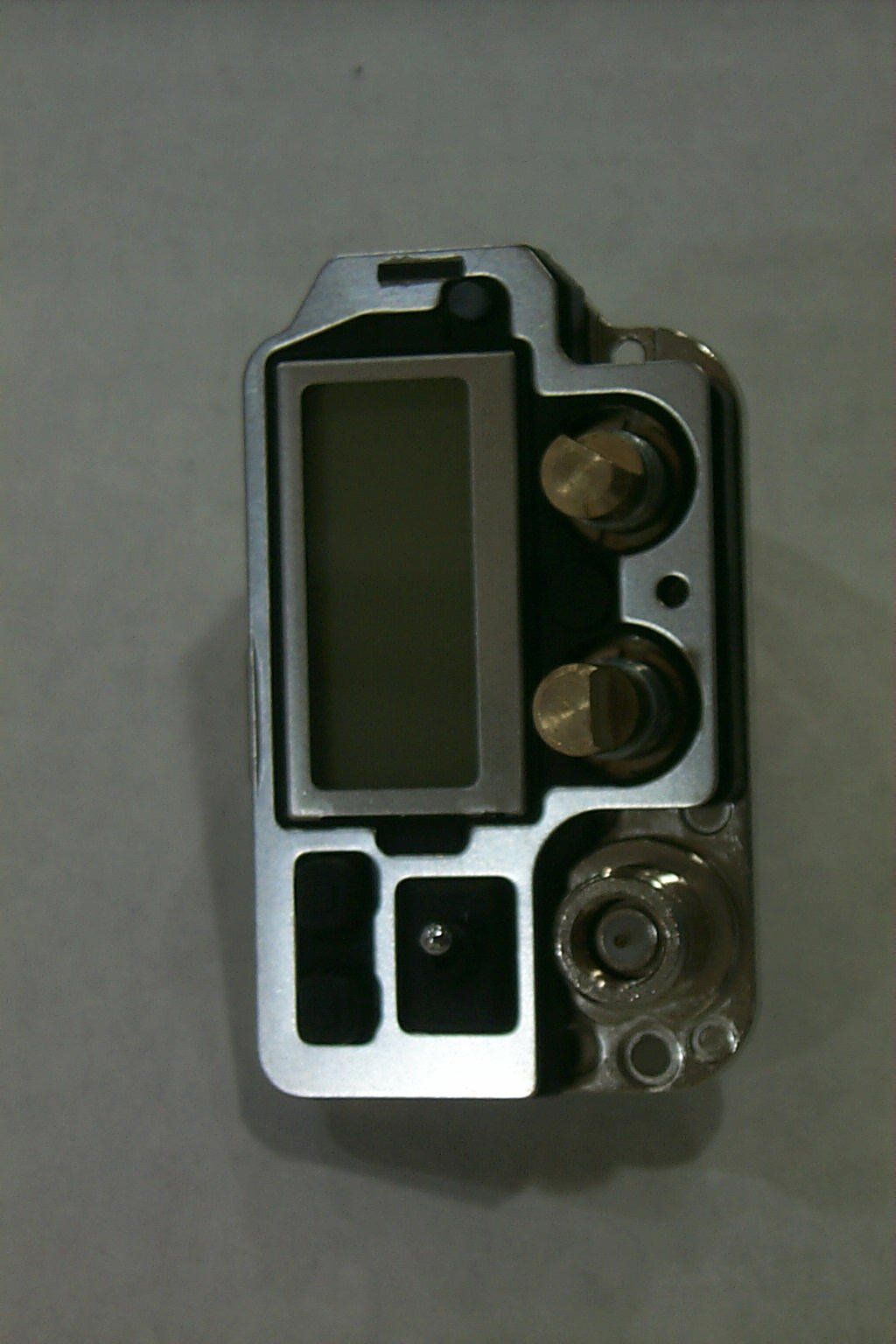
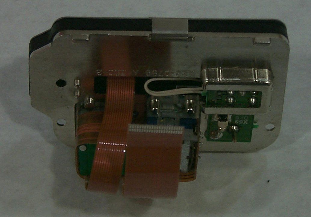
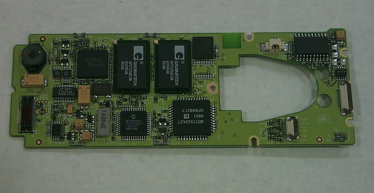
- P-801T VOICE TERMINAL RADIO
- Frequency Range
- 806.00000000 - 824.00000000
- Company
- Harris Corporation
- Country
- United States
Documents & Files
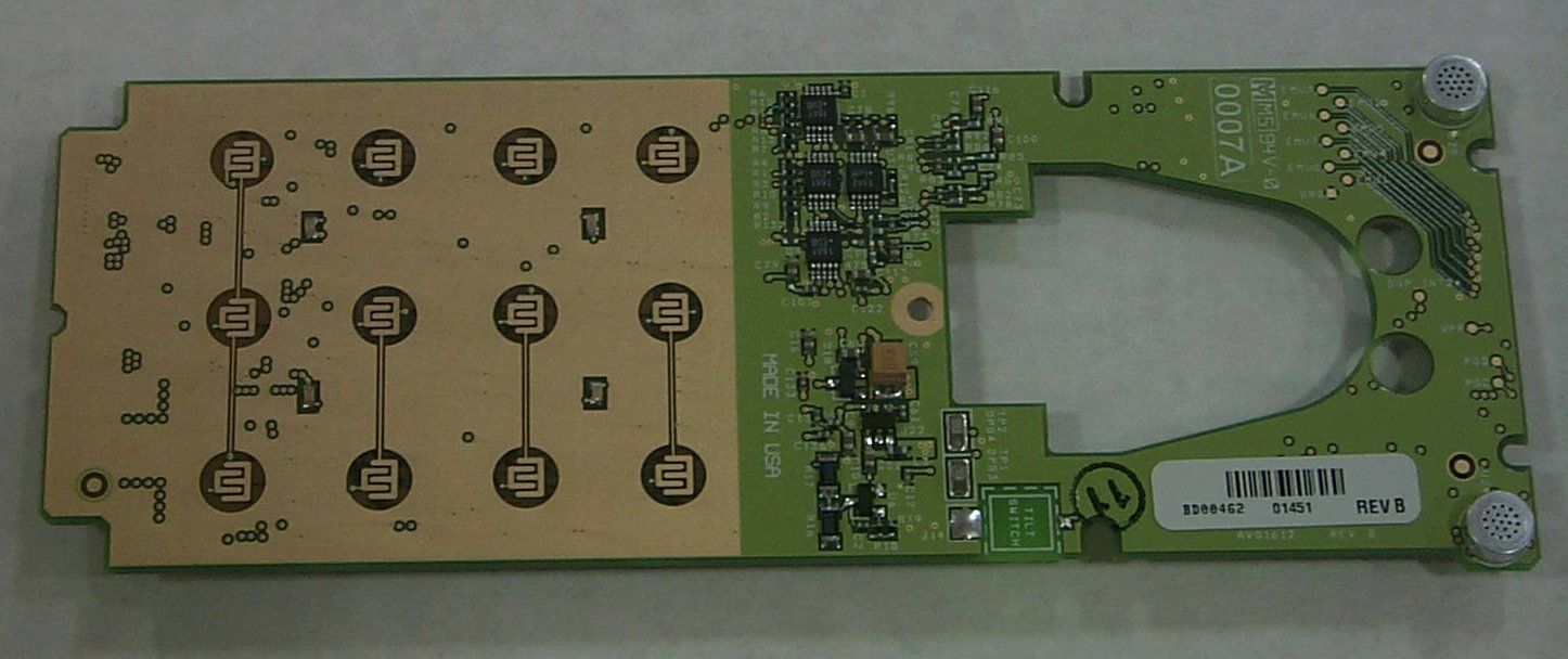
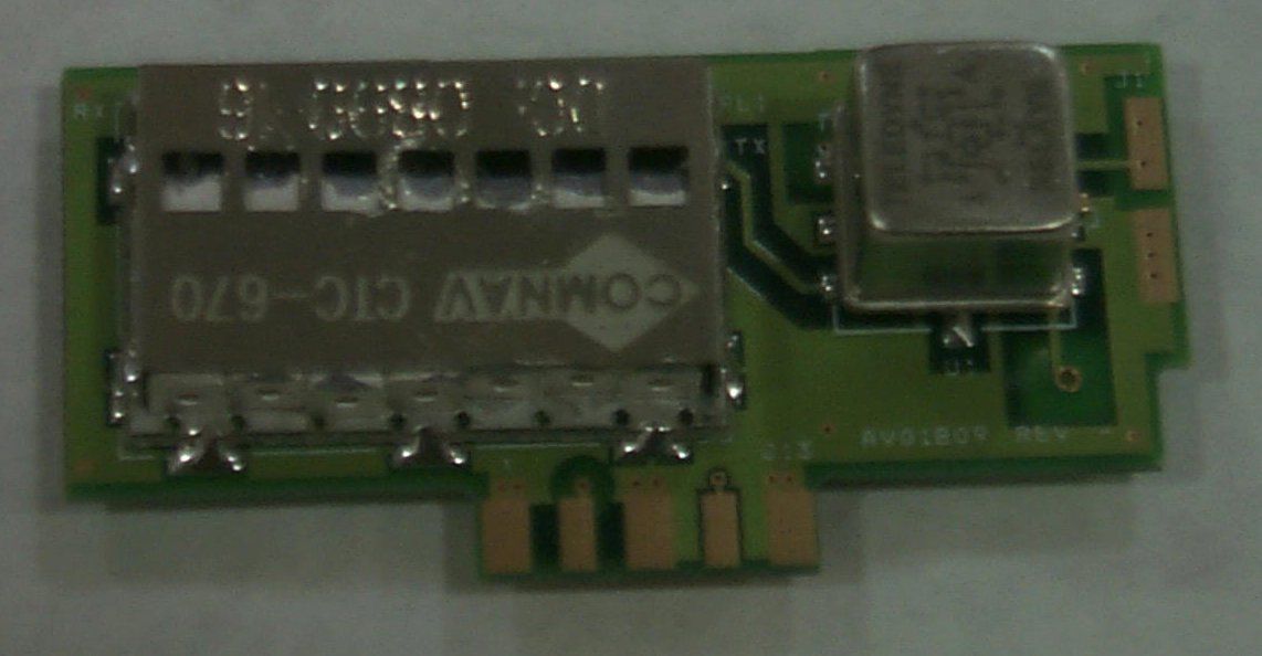
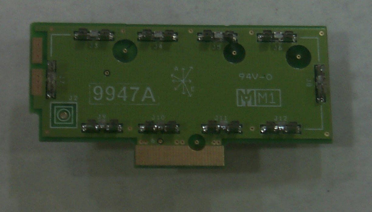
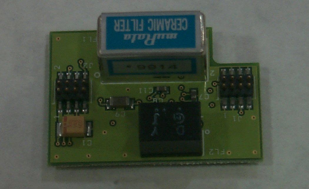
Document Text
Text extracted from the exhibit documents filed with the FCC. Open a document above to read the original.
Users Manual
P-801 User’s Manual Page 1 * P-801 User’s ManualVoice Terminal Radio P-801 User’s ManualPage 2Notices to the userWarnin g • Government law prohibits the operation of unlicensed transmitters within the territories under government control. • Illegal operation is punishable by fine or imprisonment or both. • Refer service to qualified technicians only.• Do not operate your transceiver in explosive atmospheres (gases, dust, fumes, etc.) FCC Warnin g This equipment generates or uses radio frequency energy. Changes or modifications to this equipment may cause harmful interference unless the modifications are expressly approved in the instruction manual. The user could lose the authority to oper-ate this equipment id an unauthorized change or modification is made. P-801 User’s Manual Page 3 P-801 User’s ManualPage 4Information to the digital device user required by the FCCFCC limits This equipment has been tested and found to comply with the limits for a Class B digital device pursuant to Part 15 of the FCC Rules. These limits are designed to provide reasonable protection against harmful interference in a residential installation. RF Interference This equipment generates and uses radio frequency energy and, if not installed and used in accordance with the instructions, may cause harmful interference to radio communications. However, there is no guarantee that the interference will not occur ina particular installation. If this equipment does cause harmful interference to radio or television reception, t he user is encouraged to try to correct the interference by one or more of the following measures. • Re-orient or relocate the receiving antenna• Increase the separation between the equipment and the receiver. • Connect the equipment to an outlet on a circuit different from that to which the receiver is connected. • Consult the a service center for technical assistance. P-801 User’s Manual Page 5 Accessory Installation Overview The P-801 can be used with a variety of optional accessories including; batteries, antennas, and microphones. This section tells you how to install the accessories before your first use of the radio. refer to each accessory manual for specifics on installation and operation. P-801 User’s ManualPage 6 P-801 User’s Manual Page 7 Installing the Battery PackPre p aration Your battery is not charged at the factory. Refer to the battery instructions and charge the battery before you install it. Procedure Follow the steps in the facing table to install your battery. Continued on next page P-801 User’s ManualPage 8Installing the Battery Pack (continued) Step Action 1 Match the four grooves on the battery pack with the corresponding catches on the back of the radio. 2 Slide the battery back along the grooves until that battery drops onto the catches. 3 Push the battery until the release latch on the base of the radio locks. P-801 User’s Manual Page 9 Installing the AntennaProcedure Follow the steps below to install the radio antenna. Step Action 1 Mate the antenna screw post with the connector on the top of the radio. 2 Turn the antenna clockwise until the antenna base is flush with the top of the radio. insert figure P-801 User’s ManualPage 10Installing the Belt HookProcedure Follow the steps below to install your radio’s belt hook. Step Action 1 Align the holes on the belt hook with the mounting holes on the radio as shown. 2 Screw the belt hook in place using the two 3x6 mm screws. P-801 User’s Manual Page 11 Installing Universal Connector AccessoriesOverview The universal connector is used to connect several types of acces-sories. Procedure Follow the steps in the table below to install accessories that use a universal connector Step Action 1 Insert the tab on the end of accessory’s connector into the slot on radio’s connector. 2 Tighten the connector screw to secure the microphone in place.The connector should be flush with the housing to keep the radio water resistant. P-801 User’s ManualPage 12Covering the Universal ConnectorWhen to cover the connector If no accessory is used with the radio, cover the universal connec-tor with the cap to keep the radio water resistant Procedure Follow the steps in the table below to cover the universal connector... Step Action 1 Insert the tab on the end of the cover connector into the slot on radio’s connector 2 Insert and tighten the 4x6 mm screw.The cover should be flush with the housing to keep the radio water resistant. P-801 User’s Manual Page 13 OpenSky Explained Overview Overview The P-801 Voice Terminal Radio is a key component of the OpenSky network. This section gives an overview of the Open-Sky system and OpenSky features and benefits· O p enSk y network The P-801 Voice Terminal Radio is a part of the OpenSky net-work. The OpenSky network is an integrated voice and data com-munications system. The network provides a communication backbone that enables voice to be converted to digital informa-tion and then transmitted over a wireless network. Data applica-tions can be used simultaneously with voice over the same network. Continued on next page P-801 User’s ManualPage 14OpenSky Explained (continued)O p enSk y features and benefits OpenSky connects seamlessly with existing applications and provides significant user benefits. OpenSky: • Provides one communication system to many users and agencies maximizing inter operability. One communication system eliminates the need for a user to carry more than one radio to communicate mission critical information. • · Allows radios to automatically roam between base stations, relieving radio users of the task of switching channels when moving to a new coverage area. • · Offers greater system availability by providing improved peak traffic for all voice and data information. • · Allows voice communication while data is being sent or received without having to switch radio modes. • · Locates users quickly and accurately in an emergency using radios equipped with the Global Positioning System (G…
Text truncated - open the document above for the full version.
Users Manual
User’s Manual P-801T Portable Radio Copyright © 2000 M/A-COM. All rights reserved. No part of this publication may be reproduced, transmitted, tra nscribed, sto red in a retrieval system or translated into any language, in any from or by any means, electronic, mechanical, photocopying, recording or otherwise, witho ut prior writte n permiss io n fro m M /A-COM. The informatio n furnis hed here in is b e lie ved to be ac c urate a nd re liab le. Ho we ver no respo ns ib ility is as s umed b y M /A-COM fo r its use, no r a ny infr inge me nt s o f pa te nts o r ot her r ights o f t hird p art ies r es ult ing fro m us e. Copyright © 2000, M/A-COM, Inc. Notice of Copyright The name M/A-COM, the OpenSky product name, and the M/A-COM and OpenSky logos are all trademarks of M/A-COM, Inc. Revision History DateUpdate byDescription of change 05/01/00Matt WachowiakNew 06/05/00Matt WachowiakGlobal revision 11/22/00Joe XavierAdded Occupational Safety Information 12/15/00Joe XavierRevised Notices to User and Occupational Safety Information M/A-COM Contact Information M/A-COM, Inc. 1011 Pawtucket Blvd. Lowell, MA 01853 Phone: 978.442.4000 Software Version: OTP 4.06 P-801 User’s Manual i Notices to the User and Safety Training Information IMPORTANT INFORMATION ON SAFE AND OPTIMAL OPERATION. READ THIS BEFORE US ING YOUR P-801 T PORTAB LE R ADIO WARNING Your P-801T radio generates RF electromagnetic energy during transmit mode. This radio is designed for and classified as “Occupational Use Only” meaning it must be used only during the course of employment by individuals aware of the hazards and the ways to minimize such hazards. This radio is NOT intended for use by the “General Population” in an uncontrolled environment. This radio has been tested and complies with the FCC RF exposure limits for “Occupational Use Only.” In addition, your P-801T radio complies with the following Standards and Guidelines with regard to RF energy and electromagnetic energy levels and evaluation of such levels for exposure to humans: • FCC OET Bulletin 65 Edition 97-01 Supplement C, Evaluating Compliance with FCC Guidelines for Human Exposure to Radio Frequency Electromagnetic Fields. • American National Standards Institute (C95.1 – 1992), IEEE Standard for Safety Levels with Respect to Human Exposure to Radio Frequency Electromagnetic Fields, 3kHz to 300 GHz. This equipment generates or uses radio frequency energy. Changes or modifications to this equipment may cause harmful interference unless the modifications are expressly approved in the instruction manual. The user could lose the authority to operate this equipment if an unauthorized change or modification is made. This equipment has been tested and found to comply with the limits for a Class B digital device pursuant to Part 15 of the FCC Rules. These limits are designed to provide reasonable protection against harmful interference in a residential installation. Government law prohibits the operation of unlicensed transmitters within the territories under government control. Illegal operation is punishable by fine or imprisonment or both. Refer service to qualified technicians only. Do not operate your transceiver in explosive atmospheres (gases, dust, fumes, etc.). This equipment generates and uses radio frequency energy and may cause harmful interference to radio communications if not installed and used in accordance with the instructions. However, there is no guarantee that the interference will not occur in a particular installation. If this equipment does cause harmful interference to radio or television reception, the user is encouraged to try to correct the interference by one or more of the following measures: • Re-orient or relocate the receiving antenna. • Increase the separation between the equipment and the receiver. • Consult a service center for technical assistance. P-801 User’s Manual ii Occupational Safety Guidelines and Safety Training Information CAUTION To ensure that your exposure to RF electromagnetic energy is within the FCC allowable limits for occupational use, always adhere to the following guidelines. Your P-801T portable radio may transmit using either an integral antenna or remote speaker microphone/antenna. When it is ON, it receives and also sends out radio frequency (RF) signals. In 1996, the Federal Communications commission (FCC) adopted RF exposure guidelines with safety limits for portable devices, based on the recommended limits of the National Council on Radiation Protection and Measurements (NCRP) and the American National Safety Institute (ANSI). The design of the P-801T Portable Radio complies with the FCC guidelines for Occupational / Controlled exposure to RF electromagnetic fields, as measured by the specific absorption rate (SAR). To assure optimal performance and make sure human exposure to RF electromagnetic energy is within the FCC guidelines, always adhere to the following: 1. Do not hold the radio less than 1 inch from your body, especially your face, ears, or eyes, while transmitting. 2. When using the radio, angle the antenna away from your body and do not allow the antenna to touch your body during transmission. 3. When using the remote speaker microphone/antenna, a separate accessory available to P-801T users, do not allow the antenna portion to be less than 1 inch from your body, especially the face, ears, or eyes, while transmitting. Do not let this antenna touch your body while transmitting. 4. The push-to-talk button should only be depressed when intending to send a voice message. 5. The radio should only be used for necessary work related communications. 6. The radio should only be used by authorized and trained personnel and should not be operated by children. 7. Do not operate your radio or replace/charge batteries in explosive atmospheres (gases, dust, fumes, etc.) or near explosive basking caps. Your radio should be turned off when installing and removing batteries. 8. Do not attempt any unauthorized modi…
Text truncated - open the document above for the full version.
ID Label/Location Info
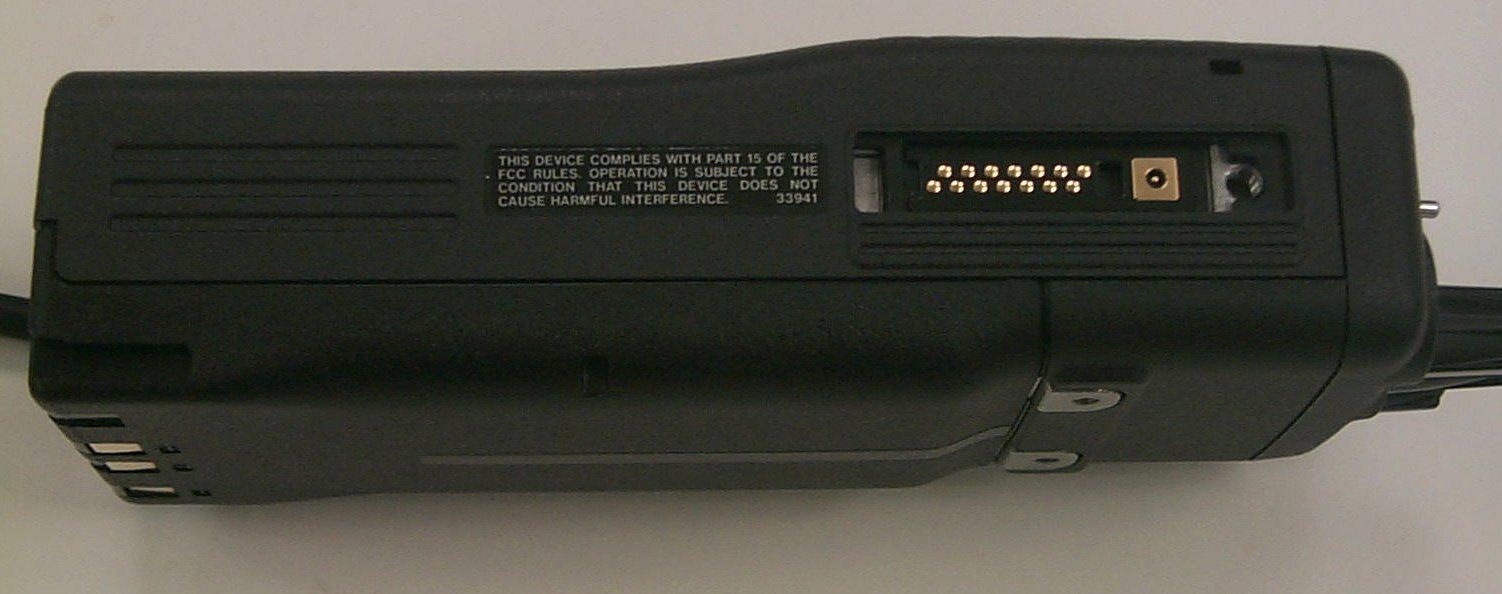
Proposed FCC Label FCC ID: BV8P-801T M/A-COM a division of AMP Incorporated Made in USA This device complies with Part 15 of the FCC Rules. Operation is subject to the condition that this device does not cause harmful interference.
RF Exposure Info
P-801T SAR Analysis Dave Gribble June 27, 2000 Summar y This document will present an electromagnetic environmental evaluation for the P-801T portable radio. Emphasis will be placed on deriving a maximum likely exposure level. This analysis will show that, based on projected worst-case parameters, the P-801T does not present an excessive RF exposure risk and comfortably meets the FCC Human Exposure limits. References: • CFR 47, 2.1093 “Radiofrequency radiation exposure evaluation: portable devices.” • FCC OET Bulletin 65, Supplement C “Additional Information for Evaluating Compliance of Mobile and Portable Devices with FCC Limits for Human Exposure to Radiofrequency Emissions” Exposure Limits: Portable devices are subject to a routine environmental evaluation for RF exposure prior to equipment authorization or use. The P-801T radio will be sold exclusively to public safety / public service customers, and never to the general public. Therefore, the P-801T will be evaluated against the “Occupational / Controlled” exposure limits (reproduced below, emphasis added). CFR 47, 2.1093 (d) (1) Limits for Occupational/Controlled exposure: 0.4 W/kg as averaged over the whole-body and spatial peak SAR not exceeding 8 W/kg as averaged over any 1 gram of tissue (defined as a tissue volume in the shape of a cube). Exceptions are the hands, wrists, feet and ankles where the spatial peak SAR shall not exceed 20 W/kg, as averaged over any 10 grams of tissue (defined as a tissue volume in the shape of a cube). Occupational/Controlled limits apply when persons are exposed as a consequence of their employment provided these persons are fully aware of and exercise control over their exposure. Awareness of exposure can be accomplished by use of warning labels or by specific training or education through appropriate means, such as an RF safety program in a work environment. The P-801T user’s manual (and training materials) will include discussion of electromagnetic exposure. Users will be warned to keep their transmit time limited and to hold the antenna at least 2 inches away from them at all times, in all configurations. Analytical Parameters The P-801T transmitter is designed for 3 Watts maximum power, in the 806-824 MHz frequency band. It is shipped with a 0dBi antenna. The user is cautioned not to hold the antenna closer than two (2) inches. The P-801T operates in two modes: analog and digital. In the analog mode, the radio limits transmission times to 30 seconds, but the transmitter is on 100% of the transmit time. In the digital mode, the radio also limits transmission time to 30 seconds, and the waveform used is a 2-slot time-division-multiple-access (TDMA), so the transmitter is on only 50% of the transmit time. Since the analog mode produces more exposure, the analog mode will be used for this analysis. In both modes, the P-801T is designed to be used in an industry-standard “90-5-5” usage model. Under this model, the radio is monitoring the channel 90% of the time, receiving (with active audio) 5% of the time, and transmitting for the final 5% of the time. For this analysis we will consider that a user might operate with a maximum 20% duty factor. This will represent a worst-case level of exposure. The FCC rules (reproduced below) allow us to make this assumption. CFR 47, 2.1093 (d): (4) For purposes of analyzing portable transmitting devices under the occupational/controlled criteria, the time-averaging provisions of the MPE guidelines identified in §1.1310 of this chapter can be used in conjunction with typical maximum duty factors to determine maximum likely exposure levels. Rather than use extensive computational modeling, this analysis will presume that the human body is not at all reflective to electromagnetic energy. In other words, this analysis will assume that the portion of the body under RF exposure will absorb all of the incident energy, and reflect none. Also, for this analysis, the human body will be considered to have only three densities. The densities used are taken from OET Bulletin 65, Supplement C. We will use 1035 kg/m 3 (=1.035 g/c m 3 ) for flesh (brain / muscle) and we will use 1850 kg/m3 (=1.85 g/cm 3 ) for bone (skull). Anal ysis Consider the case of the user operating the transmitter with the antenna two (2) inches from his head. The transmitter maximum output power is radiated from the antenna in a spherical pattern (because the antenna has 0dBi gain). Consider a series of concentric spheres centered at the antenna. The first sphere which touches the users head will have the highest power density. The surface area of this sphere is: 2 4 rAsphere π= Since the antenna is isotropic, we can assume that the power is spread evenly over the surface of this sphere. This means that: 2 4 r P tyPowerDensi π = At a radius of 2 inches (r=5.1cm), the power density on the surface of the sphere is 9.2 mW/cm 2 . Now consider the flesh that the sphere is touching. The peak exposure limit is written in terms of W/kg, averaged over any 1 gram of tissue in the shape of a cube. To relate tissue mass (grams) to power absorption, we need to determine how much of the sphere is subtended by the tissue in question. Since we are assuming the tissue is in the head, it seems appropriate to use skull tissue (density=1.85 g/cm 3 ). 1 gram of skull tissue would then correspond to a 0.54 cm 3 sized cube. This cube of skull tissue would measure 0.81 cm on each side, and would cover approximately 0.66cm 2 of the radiation sphere’s surface area. Surprisingly, due to its lower density, it is more appropriate to assume that the users head is made of flesh (muscle or brain) rather than skull. The lower flesh density (=1.035 g/cm 3 ) leads to a 1 gram flesh cube measuring 0.99 cm on each side. This cube covers approximately 0.98cm 2 of the radiation sphere’s surface area. Since the tissue cube covers 0.98cm 2 of the radiation sphere, and since the sphere’s power density is 9.2mW/cm 2 , we can see that the tissue…
Text truncated - open the document above for the full version.
RF Exposure Info
SAR COMPLIANCE TESTING OF M/A-COM MODEL P-801T PORTABLE PUSH-TO-TALK RADIO FINAL TECHNICAL REPORT October 24, 2000 Submitted to:Mr. A. E. (Andy) Moysenko Manager, Technology Programs M/A-Com, Inc. 1011 Pawtucket Blvd. Lowell, MA 01853-3295 Submitted by:Om P. Gandhi Professor of Electrical Engineering University of Utah 50 S Central Campus Dr., Rm. 3280 Salt Lake City, UT 84112-9206 i SAR COMPLIANCE TESTING OF M/A-COM MODEL P-801T PORTABLE PUSH-TO-TALK RADIO Summary A widely-accepted finite-difference time-domain (FDTD) computational technique has been used for a heterogeneous, anatomically-based model of the human to determine maximum peak 1-g specific absorption rates (SAR) for four typical configurations of M/A-Com Model P- 801T Portable Push-to-Talk Radio for two midband frequencies of the transmission bands. The FDTD-calculated gains of the two antennas of -0.1 and -3.2 dBi compare extremely well with gains of 0 and -3.0 dBi measured for these antennas. The maximum 1-g SARs for the four considered configurations of the radio for the analog (100% duty cycle mode) vary from 1.53 to 7.02 W/kg with the highest SAR when the "microphone" is mounted on the lapel at the shoulder. The SAR values are less than the FCC occupational limit of 8.0 W/kg for any 1-g of tissue. For a vast majority of situations, the radio will be used in the TDMA mode with 50% duty cycle. Under these conditions, the maximum 1-g SARs would be one-half of the above values and would vary from 0.77 to 3.51 W/kg for the four configurations, respectively. 1 SAR COMPLIANCE TESTING OF M/A-COM MODEL P-801T PORTABLE PUSH-TO-TALK RADIO I. Introduction The U.S. Federal Communications Commission (FCC) has adopted limits of human exposure to RF emissions from mobile and portable devices that are regulated by the FCC [1]. The FCC has also issued Supplement C (Edition 97-01) to OET Bulletin 65 defining both the measurement and the computational procedures that should be followed for evaluating compliance of mobile and portable devices with FCC limits for human exposure to radiofrequency emissions [2]. The partial-body SAR limits prescribed by the FCC are 8.0 W/kg for occupational/controlled exposures and 1.6 W/kg for general population/uncontrolled exposures. The maximum partial-body SAR is to be obtained by averaging over any 1 g of tissue defined as a tissue volume in the shape of a cube [1, 2]. The M/A-Com Model P-801T Two-Way Portable Radio FCC ID#BV8P-801T can radiate up to a maximum power of 3 W over the frequency bands 806-824 MHz and 851-870 MHz. According to the manufacturer, the equipment is to be sold exclusively to public safety/public service agencies and not to the general public. Training will be required on use of this equipment prior to issue to users. SAR compliance testing is thus required for the peak 1-g SAR of 8.0 W/kg for occupational/controlled exposures [1, 2]. According to FCC 96-326 [1], "use of appropriate numerical and computational techniques, such as FDTD analysis, is acceptable for demonstrating compliance with the SAR values. Studies by O. P. Gandhi and others indicate that such techniques offer valid means to determine energy absorption characteristics in exposed subjects." For SAR compliance testing of the M/A-Com Model P-801T Portable Radio, we have used the widely accepted FDTD method for the anatomically-based model of the human body [3, 4]. Some reasons for selecting the numerical method, rather than the experimental phantom model, are as follows: 1. The experimental phantom models of the face or the human waist, two of the locations where the two-way radio is held in operation are not readily available. 2 2. Anatomically-based models have the advantage of modeling the curved shapes as well as the heterogeneities of the tissues. 3. Flat phantom models may be used. But, as given in Table 4, these models tend to grossly overestimate the SARs because of lack of curvature such as for the face and the body. Using the numerical method results in putting some of the tissues at realistic distances which are generally greater than those for a flat phantom model (see Figs. 3, 6, 9, 10 for visualization of the Radio P-801T vis à vis the human model). 4. Some individuals have alluded to leakage electromagnetic fields from the electronic components in the handset. There is, however, no proof for this allegation. In fact, as given in [5], the experimentally-determined SARs for 10 experimental wireless handsets five each at 835 and 1900 MHz were within ± 20 percent (± 1 dB) of those determined from the FDTD computational method. This slight difference of ± 1 dB may well be due to the fact that the numerical method uses a 15 tissue heterogeneous anatomic model of the head and neck while the experimental phantom uses a relatively thin shell with a homogeneous liquid in it. 5. Lastly, the manufacturer uses a well-shielded chassis of the handset thus minimizing any leakage radiation from the internal electronic components. This is described in detail in Section II. II. The M/A-Com Model P-801T Portable Push-to-Talk Radio A photograph of the M/A-Com Model P-801T Radio is given in Fig. 1. As aforementioned, the radio transmits in the frequency band 806-824 MHz and 851-870 MHz with a maximum ERP of three watts or 34.8 dBm. The approximate dimensions of the radio are as follows: width 2.3", depth 1.5" and height 6.1". As seen in Fig. 1, a sleeve type, nominal half wave dipole antenna is mounted in the back right-hand corner at the top of the die cast aluminum chassis in rugged polycarbonate housing of the handset. The sleeve type antenna has the following dimensions: 3 Diameter of unshielded wire (for the upper part of the antenna) = 1.7 mm Diameter of the rubber sheathing around the antenna = 0.22" (5.6 mm) Unshielded length of the antenna = 159 mm Length of the metallic shielding sleeve (at the base of the antenna) = 16 mm Diameter of the shielding sleeve = 0.75" (19.05 mm) Thickness of the rubber sheathing around …
Text truncated - open the document above for the full version.
RF Exposure Info
1 Table 1.Dielectric properties of the various tissues assumed for the model of the human body [7]. Tissue Mass Density 10 3 kg / m 3 815.0 MHz860.5 MHz ε r ε r σ S/m σ S/m Muscle Fat Bone (cancellous) Cartilage Skin Nerve Intestine Spleen Heart Blood Liver Kidney Lung (inflated) CSF Eye humor Sclera Lens Stomach Pancreas, paratid gland Brain, pineal gland, pituitary gland 1.04 0.92 1.85 1.10 1.01 1.04 1.04 1.05 1.03 1.06 1.03 1.05 0.35 1.01 1.01 1.17 1.10 1.05 1.05 1.03 56.17 11.37 16.75 42.97 44.17 32.81 60.11 57.75 60.49 61.65 47.26 59.41 22.17 68.83 68.92 55.51 41.37 65.31 59.89 46.18 0.94 0.10 0.23 0.74 0.83 0.55 2.12 1.23 1.19 1.50 0.82 1.34 0.44 2.38 1.61 1.14 0.62 1.15 1.01 0.74 56.05 11.35 16.68 42.80 43.93 32.65 59.76 57.43 60.16 61.48 47.02 59.00 22.08 68.73 68.91 55.38 41.28 65.18 59.77 45.97 0.96 0.11 0.23 0.76 0.84 0.56 2.14 1.25 1.21 1.52 0.84 1.37 0.45 2.40 1.62 1.15 0.63 1.17 1.02 0.75 Configuration 1 Configuration 2 Configuration 3 Configuration 4 Radio with “1/2 wave” antenna held at 1 inch in front of the mouth (See Fig. 3) Microphone with “1/4 wave” antenna clipped to the lapel at shoulder (See Fig. 10) Radio with “1/2 wave” antenna in a holster mounted at back side of waist (See Fig. 6) Microphone with “1/4 wave” antenna held at 1 inch in front of the mouth (See Fig. 9) Resolution (mm) Human model (cells) FDTD dimensions (cells) Memory requirement Calculation periods 1.974 x 1.974 x 2 101 x 113 x 127 121 x 160 x 196 268 MB 8 2.961 x 2.961 x 3 116 x 98 x 265 130 x 135 x 280 272 MB 8 1.974 x 1.974 x 2 101 x 113 x 127 121 x 160 x 196 268 MB 10 2.961 x 2.961 x 3 120 x 127 x 167 140 x 147 x 187 347 MB 15 Table 2. Model size and computing requirements for SAR calculations for M/A-Com P-801T Portable Radio. 2 Table 3. Models used to represent the P-801T Radio and the microphone. Handset Handset Dimensions P-801T Radio With “1/2 wave” Antenna 2.3′′ × 1.5′′ × 6.1′′ 2.25′′ × 1′′ × 2.5′′ Microphone With “1/4 wave” Antenna (28 + 1 + 1) x (18 + 1 + 1)x (76 + 1 + 1) (18 + 1 + 1) x (11 + 1 + 1) x (50 + 1 + 1) 19.05, 16 mm 6 x 6 x 8 4 x 4 x 5 1.7, 159 mm 1, 80 1, 53 (27 + 1 + 1) x (11 + 1 + 1)x (30 + 1 + 1) (18 + 1 + 1) x (7 + 1 + 1) x (19 + 1 + 1) 19.05, 16 mm 6 x 6 x 8 4 x 4 x 5 1.7, 69 mm 1, 35 1, 23 Sleeve, diameter, height No. of voxels (1.974 x 1.974 x 2 mm models) No. of voxels (2.961 x 2.961 x 3 mm models) Antenna, diameter, height No. of voxels (1.974 x 1.974 x 2 mm models) No. of voxels (2.961 x 2.961 x 3 mm models) No. of voxels for 1.974 x 1.974 x 2 mm models (Configurations 1, 3) No. of voxels for 2.961 x 2.961 x 3 mm models (Configurations 2, 4) * * Sleeve Antenna Wire (Unshielded Region) 1 + 1 cells along each of the directions are taken because of the need to represent plastic covering of the handsets. Both the sleeve and the antenna are also assumed to be covered with 1 cell on each of the sides to represent rubber sheathing . ( ε = 4) r * ** ** ** 3 Handheld Radio with “1/2 wave” antenna held at 2 inches from the face to the antenna (see Fig. 3a, b) For a Flat Phantom Radio with “1/2 wave” antenna belt-mounted at waist against the back left side with a distance of 1 inch due to thickness of holster (see Fig. 6a, b) Handheld, “Microphone” with “1/4 wave” antenna held at 2 inches from the face to the antenna (see Fig. 9a, b) For a Flat Phantom “Microphone” with “1/4 wave” antenna mounted on lapel at the shoulder for a distance of 11 mm from the body (due to thickness of the clip and the clothing (see Figs. 10a, b) 1 2 3 4 1.53 3.53 5.09 3.42 7.44 7.02 0.27 --- 0 1.22 --- 0.10 0.27 --- 0 1.30 --- 0 Configuration Description Body Left Eye Right Eye Max 1-g SAR (W/kg) 1.55 --- 5.15 3.39 --- 6.98 0.25 --- 0 1.17 --- 0.11 0.26 --- 0 1.28 --- 0 Body Left Eye Right Eye Max 1-g SAR (W/kg) 815 MHz 860.5 MHz Table 4. The calculated maximum 1-g SARs for the body (face in Configurations 1 and 3) and the left and right eyes for four configurations of the M/A-Com Model P-801T Portable Radio radiating 3W at 815 or 860.5 MHz in the analog (100% duty cycle mode). * * All of the SARs would be reduced by a factor of 2 for the TDMA (50% duty cycle) mode used in the vast majority of cases.
RF Exposure Info
Fig. 1. Photograph of the M/A-Com Model P-801T Two-Way Radio.
RF Exposure Info
Fig. 2.A cross sectional diagram of the M/A-Com Model P-801T Radio showing shielding.
RF Exposure Info
Fig. 3.The M/A-Com Portable Radio P-801T with "half-wave" antenna in front of the mouth.
RF Exposure Info
Fig. 4. The M/A-Com Portable Radio P-801T in belt mount holster.
RF Exposure Info
Fig. 5. Detail of belt clip showing spacing and metallic swivel.
RF Exposure Info
Fig. 6.The M/A-Com Portable Radio P-801T with "half-wave" antenna belt mounted at the waist on the back side.
RF Exposure Info
Fig. 7. Microphone with "1/4-wave" Antenna.
RF Exposure Info
Fig. 8. Microphone internal view.
RF Exposure Info
Fig. 9.The M/A-Com "Microphone" Portable Radio P-801T with "quarter-wave" antenna held in front of the mouth.
RF Exposure Info
Fig. 10.The M/A-Com "Microphone" Portable Radio P-801T with "quarter-wave" antenna mounted on lapel at the shoulder.
RF Exposure Info
z y x E x E y E y E x E x E y E z E z E z (i,j,k) H x H y H z Fig. 11.A unit cell of Yee lattice indicating positions for the various field components.
RF Exposure Info
Fig. 12.The calculated radiation pattern for the horizontal xy plane for the M/A-Com Model P-801T Radio (with nominal "1/2 wave" antenna) held in free space.
RF Exposure Info
Fig. 13. The calculated radiation pattern for the horizontal xy plane for the Microphone (with nominal "1/4 wave" antenna) held in free space.
RF Exposure Info
User’s Manual P-801T Portable Radio Copyright © 2000 M/A-COM. All rights reserved. No part of this publication may be reproduced, transmitted, tra nscribed, sto red in a retrieval system or translated into any language, in any from or by any means, electronic, mechanical, photocopying, recording or otherwise, witho ut prior writte n permiss io n fro m M /A-COM. The informatio n…
Text truncated - open the document above for the full version.
Contact Information
Applicant
Thomas Camper, Jr.(Regulatory Manager)
Technical Contact
CHOMERICS TEST SERVICESPATRICIA L TERILLI
[email protected]781-939-4158
77 DRAGON COURT · WOBURN, Massachusetts · United States
Non-Technical Contact
CHOMERICS TEST SERVICESPATRICIA L TERILLI
[email protected]781-939-4158
Test Firm
Chomerics Test ServicesDavid Inman
Technical Specifications
| # | Rule Parts | Frequency Range | Power Output | Emission | Tolerance |
|---|---|---|---|---|---|
| 6 | 9 | 806 MHz - 824 MHz | 3 W | 12K0F3E | 0.1 ppm |
Other Applications from Harris Corporation
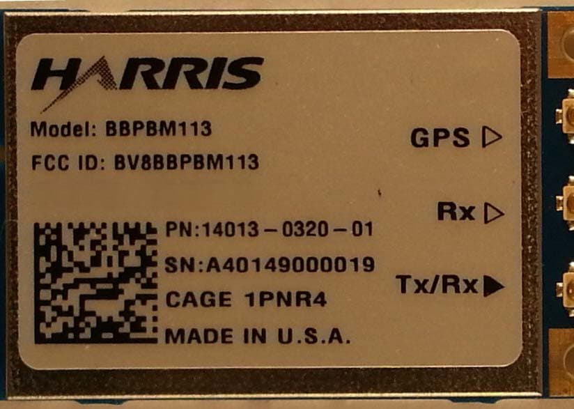
BV8BBPBM113
Apr 11, 2013Wireless Licensed Module
Equipment Class
TNB - Licensed Non-Broadcast Station Transmitter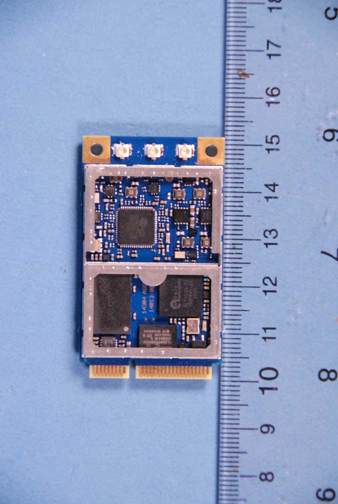
BV8BBPBM100
Feb 09, 2012700 MHz LTE Wireless Module
Equipment Class
TNB - Licensed Non-Broadcast Station Transmitter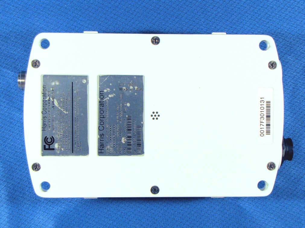
BV8WM4900CL
Nov 21, 2010Client 4.9 GHz 802.16 VBB 5/10
Equipment Class
TNB - Licensed Non-Broadcast Station Transmitter
BV8VIDA-BB-CL
Apr 11, 2007VIDA Broadband High Power Client
Equipment Class
TNB - Licensed Non-Broadcast Station Transmitter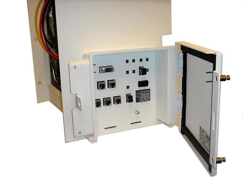
BV8CS900
Apr 08, 2007OpenSky 900 MHz Cell Site
Equipment Class
TNB - Licensed Non-Broadcast Station Transmitter