BV8P800Portable Radio Model P800
Harris Corporation
Click to zoom
Application Details
- Equipment Class
- TNB - Licensed Non-Broadcast Station Transmitter
- Date of Grant
- Apr 04, 2005
- Application Purpose
- Original Equipment
- Date of Application
- Jul 24, 2002
- Equipment Note
- Portable Radio Model P800
- Frequency Range
- 821.00000000 - 824.00000000
- Company
- Harris Corporation
- Country
- United States
Documents & Files
Document Text
Text extracted from the exhibit documents filed with the FCC. Open a document above to read the original.
Users Manual
OpenSky Digital Radio Portable Radio Model P800 Users Manual P800 User’s Manual 1 CHAPTER 1 Welcome to the OpenSky Network Chapter 1 Safety Notices 3 Notices to the User and Safety Training Information 3 Occupational Safety Guidelines and Safety Training Information 5 OpenSky Overview 7 Internet Protocol (IP) Network 7 Integrated Voice and Data 8 Digitized Voice, Text and Graphics 8 Multi-Agency Coverage 10 Promotes Interagency Cooperation 10 Connectivity with Legacy Equipment 11 Improved Coverage and Signal Strength 11 Better Peak-Time Performance 12 Software-Configured Device 12 Software Upgradeable 13 Welcome to the OpenSky Network—CHAPTER 1 P800 User’s Manual 3 Safety Notices IMPORTANT INFORMATION ON SAFE AND OPTIMAL OPERATION. READ THIS BEFORE USING YOUR P800 PORTABLE RADIO. Notices to the User and Safety Training Information WARNING Your P800 radio generates RF electromagnetic energy during transmit mode. This radio is designed for and classified as “Occupational Use Only” meaning it must be used only during the course of employment by individuals aware of the hazards and the ways to minimize such hazards. This radio is NOT intended for use by the “General Population” in an uncontrolled environment. The OpenSky P800 portable radio has been tested and complies with the FCC RF exposure limits for “Occupational Use Only.” In addition, your P-800 radio complies with the following Standards and Guidelines with regard to RF energy and electromagnetic energy levels and evaluation of such levels for exposure to humans: • FCC OET Bulletin 65 Edition 97-01 Supplement C, Evaluating Compliance with FCC Guidelines for Human Exposure to Radio Frequency Electromagnetic Fields. • American National Standards Institute (C95.1– 1992), IEEE Standard for Safety Levels with Respect to Human Exposure to Radio Frequency Electromagnetic Fields, 3kHz to 300 GHz. This equipment generates or uses radio frequency energy. Changes or modifications to this equipment may cause harmful interference unless the modifications are expressly approved in the instruction manual. The user could lose the authority to operate this equipment if an unauthorized change or modification is made. CHAPTER 1—Advanced Radio Operations 4 P800 User’s Manual This equipment has been tested and found to comply with the limits for a Class B digital device pursuant to Part 15 of the FCC Rules. These limits are designed to provide reasonable protection against harmful interference in a residential installation. Government law prohibits the operation of unlicensed transmitters within the territories under government control. Illegal operation is punishable by fine or imprisonment or both. Refer service to qualified technicians only. Do not operate your transceiver in explosive atmospheres (gases, dust, fumes, etc.). This equipment generates and uses radio frequency energy and may cause harmful interference to radio communications if not installed and used in accordance with the instructions. However, there is no guarantee that the interference will not occur in a particular installation. If this equipment does cause harmful interference to radio or television reception, the user is encouraged to try to correct the interference by one or more of the following measures: • Re-orient or relocate the receiving antenna. • Increase the separation between the equipment and the receiver. • Consult a service center for technical assistance. Welcome to the OpenSky Network—CHAPTER 1 P800 User’s Manual 5 Occupational Safety Guidelines and Safety Training Information CAUTION. To ensure that your exposure to RF electromagnetic energy is within the FCC allowable limits for occupational use, always adhere to the guidelines below. Your P800 portable radio may transmits using the integral antenna. When the radio is ON, it receives and also sends out radio frequency (RF) signals. In 1996, the Federal Communications Commission (FCC) adopted RF exposure guidelines with safety limits for portable devices, based on the recommended limits of the National Council on Radiation Protection and Measurements (NCRP) and the American National Safety Institute (ANSI). The design of the P800 Portable Radio complies with the FCC guidelines for Occupational / Controlled exposure to RF electromagnetic fields, as measured by the specific absorption rate (SAR). To assure optimal performance and make sure human exposure to RF electromagnetic energy is within the FCC guidelines, always adhere to the following: 1. Do not hold the radio less than 1 inch from your body, especially your face, ears, or eyes, while transmitting. 2. When using the radio, angle the antenna away from your body and do not allow the antenna to touch your body during transmission. 3. The push-to-talk button should only be depressed when intending to send a voice message. 4. The radio should only be used for necessary work related communications. 5. The radio should only be used by authorized and trained personnel and should not be operated by children. 6. Do not operate your radio or replace/charge batteries in explosive atmospheres (gases, dust, fumes, etc.) or near explosive basking caps. Your radio should be turned off when installing and removing batteries. CHAPTER 1—Advanced Radio Operations 6 P800 User’s Manual 7. Do not attempt any unauthorized modification to the radio. Changes or modifications to the radio may cause harmful interference. Service of the radio should only be performed by qualified personnel. 8. Always use M/A-COM authorized accessories (antennas, batteries, belt clips, speakers/mic, etc.). Use of unauthorized accessories can cause the FCC RF exposure compliance requirements to be exceeded. The information listed above provides the user with the information needed to make him or her aware of a RF exposure, and what to do to assure that this radio operates within the FCC exposure limits of this radio. Welcome to the OpenSky Network—CHAPTER 1 P800 User’s Manual 7 OpenSky Overview M/A-COM’s O…
Text truncated - open the document above for the full version.
Users Manual
OpenSky Digital Radio Portable Radio Model P800 Users Manual P800 User’s Manual 1 CHAPTER 1 Welcome to the OpenSky Network Chapter 1 Safety Notices 3 Notices to the User and Safety Training Information 3 Occupational Safety Guidelines and Safety Training Information 5 OpenSky Overview 7 Internet Protocol (IP) Network 7 Integrated Voice and Data 8 Digitized Voice, Text and Graphics 8 Multi-Agency Coverage 10 Promotes Interagency Cooperation 10 Connectivity with Legacy Equipment 11 Improved Coverage and Signal Strength 11 Better Peak-Time Performance 12 Software-Configured Device 12 Software Upgradeable 13 Welcome to the OpenSky Network—CHAPTER 1 P800 User’s Manual 3 Safety Notices IMPORTANT INFORMATION ON SAFE AND OPTIMAL OPERATION. READ THIS BEFORE USING YOUR P800 PORTABLE RADIO. Notices to the User and Safety Training Information WARNING Your P800 radio generates RF electromagnetic energy during transmit mode. This radio is designed for and classified as “Occupational Use Only” meaning it must be used only during the course of employment by individuals aware of the hazards and the ways to minimize such hazards. This radio is NOT intended for use by the “General Population” in an uncontrolled environment. The OpenSky P800 portable radio has been tested and complies with the FCC RF exposure limits for “Occupational Use Only.” DO NOT transmit for more than 50% of total radio use time (“50% duty cycle”). Transmitting more than 50% of the time can cause FCC RF exposure compliance requirements to be exceeded. The radio is transmitting when the “TX” indicator light is flashing. The radio will transmit by pressing the “PTT” button. In addition, your P-800 radio complies with the following Standards and Guidelines with regard to RF energy and electromagnetic energy levels and evaluation of such levels for exposure to humans: CHAPTER 1—Advanced Radio Operations 4 P800 User’s Manual • FCC OET Bulletin 65 Edition 97-01 Supplement C, Evaluating Compliance with FCC Guidelines for Human Exposure to Radio Frequency Electromagnetic Fields. • American National Standards Institute (C95.1– 1992), IEEE Standard for Safety Levels with Respect to Human Exposure to Radio Frequency Electromagnetic Fields, 3kHz to 300 GHz. This equipment generates or uses radio frequency energy. Changes or modifications to this equipment may cause harmful interference unless the modifications are expressly approved in the instruction manual. The user could lose the authority to operate this equipment if an unauthorized change or modification is made. This equipment has been tested and found to comply with the limits for a Class B digital device pursuant to Part 15 of the FCC Rules. These limits are designed to provide reasonable protection against harmful interference in a residential installation. Government law prohibits the operation of unlicensed transmitters within the territories under government control. Illegal operation is punishable by fine or imprisonment or both. Refer service to qualified technicians only. Do not operate your transceiver in explosive atmospheres (gases, dust, fumes, etc.). This equipment generates and uses radio frequency energy and may cause harmful interference to radio communications if not installed and used in accordance with the instructions. However, there is no guarantee that the interference will not occur in a particular installation. If this equipment does cause harmful interference to radio or television reception, the user is encouraged to try to correct the interference by one or more of the following measures: • Re-orient or relocate the receiving antenna. • Increase the separation between the equipment and the receiver. • Consult a service center for technical assistance. Welcome to the OpenSky Network—CHAPTER 1 P800 User’s Manual 5 Occupational Safety Guidelines and Safety Training Information CAUTION. To ensure that your exposure to RF electromagnetic energy is within the FCC allowable limits for occupational use, always adhere to the guidelines below. Your P800 portable radio may transmits using the integral antenna. When the radio is ON, it receives and also sends out radio frequency (RF) signals. In 1996, the Federal Communications Commission (FCC) adopted RF exposure guidelines with safety limits for portable devices, based on the recommended limits of the National Council on Radiation Protection and Measurements (NCRP) and the American National Safety Institute (ANSI). The design of the P800 Portable Radio complies with the FCC guidelines for Occupational / Controlled exposure to RF electromagnetic fields, as measured by the specific absorption rate (SAR). To assure optimal performance and make sure human exposure to RF electromagnetic energy is within the FCC guidelines, always adhere to the following: 1. Do not hold the radio less than 1 inch from your body, especially your face, ears, or eyes, while transmitting. 2. When using the radio, angle the antenna away from your body and do not allow the antenna to touch your body during transmission. 3. The push-to-talk button should only be depressed when intending to send a voice message. 4. The radio should only be used for necessary work related communications. 5. The radio should only be used by authorized and trained personnel and should not be operated by children. 6. Do not operate your radio or replace/charge batteries in explosive atmospheres (gases, dust, fumes, etc.) or near explosive basking caps. Your radio should be turned off when installing and removing batteries. CHAPTER 1—Advanced Radio Operations 6 P800 User’s Manual 7. Do not attempt any unauthorized modification to the radio. Changes or modifications to the radio may cause harmful interference. Service of the radio should only be performed by qualified personnel. 8. Always use M/A-COM authorized accessories (antennas, batteries, belt clips, speakers/mic, etc.). Use of unauthorized accessories can cause the FCC RF exposure compliance requirements to be exceeded…
Text truncated - open the document above for the full version.
Cover Letter(s)
14 June 2002 Federal Communications Commission Washington, DC 20554 Subject: M/A-COM Submission for FCC Grant of Equipment Authorization Reference: M/A-COM's OpenSky ® P800 Portable Transceiver To Whom It May Concern: M/A-COM, Inc. hereby requests that certain sections, exhibits and the like, to our attached submission be treated by the FCC as confidential information. The sections that require confidentiality is, for the most part all of the Section entitled Block Diagrams and Schematics and includes the following technical information: • Detailed Theory of Operation • Any and all Block Diagrams and explanatory text • Processing Kernel Schematic, Drawing No. HE01030 • Transceiver Schematic, Drawing No. HE01032 • High Power Amplifier Schematic, Drawing No. HE00515 The above technical information, which is explicitly characterized in our submission, describes in detail how our product is built and its theory of operation. This level of technical information, if disclosed outside the FCC, would cause irreparable harm to M/A-COM from a competitive standpoint. Therefore, we respectfully request that the technical information listed herein and fully described in our submission attached hereto be treated as confidential information and not be disclosed outside of the FCC. Sincerely, Noreen Kealey Contracts Administrator Enclosures
Cover Letter(s)
M/A-COM, Inc. 221 Jefferson Ridge Parkway Lynchburg, VA 24501 [email protected] Regulatory Manager Telephone: (434) 455-9377 Fax: (434) 455-6815 March 6, 2003 Federal Communications Commission Authorization & Evaluation Division 7435 Oakland Mills Road Columbia Maryland 21046 Attention: Equipment Authorization Branch Subject: FCC ID: BV8P800 Correspondence Reference # 24608, Confirmation #’s EA 244045 Stan Lyles, M/A-COM, Inc. is answering the questions regarding the EA 244045: Question 1 is answered by additional plots of the emissions including mask, mask H was used for all plots, as it is the most stringent. The plots were taken at an earlier date of an electrically identical model. Questions 2 and 3 are concerning talk-around mode, at this time, with this product, we are not asking for a talk around option any other representation to the contrary is in error, the original 731 asks for an F1D and F1E designator in the 806- 824 MHz band this is still the case. We will add the talk-around mode with an analog emission designator in the future. Question 4:The details of the 50% duty cycle signal are as follows: The on and off times are 30 mS in each state. While transmitting in this mode the modulation is 4 level GFSK at 3 watts peak output power. The modulator is fed a pseudorandom string from the processor. This mode is not documented to the user as it is for test only. This signal simulates the radio's behavior in Open Sky Trunked mode where we TDMA the channel into two 30 mS time slices. The radio was measured in this mode for two reasons, first it accurately represents the Open Sky Protocol behavior, Second if the portable is allowed to transmit at full power for extended periods of time i.e. 10 minutes or longer it gets hot enough that the thermal management circuitry backs off the transmit power. The SAR test required long periods of transmission at full power so the TDMA mode was judged best. Question 5: There are only a couple of other details. The radio, in data mode, always uses 4 level GFSK modulation. The standard modes for the radio are either 2 slot or 4 slot TDMA. The radio also has a mode where it transmits at 17% duty cycle; this is used for registration and channel access requests. The carrier ramp up and down times are 200 uS, < 1/100 of the total burst time. Question 6, duty factor is not controllable by the end user and is at the most 50% for a push-to-talk radio, Sar measurements were taken with a 50% signal modulation duty cycle. Duty cycle is also limited due the reasons listed in question 4. This is also a controlled exposure radio. Control of SAR is covered in some detail on page 6 and 7 of the existing manual. Questions 7,8, and 9 are answered in the SAR addendum from ITS which will be upload along with this cover letter. Regards, Bryan McWatters Regulatory Manager Telephone: (434) 455-9377 Fax: (434) 455-6815 [email protected]
Cover Letter(s)
M/A-COM, Inc. 221 Jefferson Ridge Parkway Lynchburg, VA 24501 [email protected] Regulatory Manager Telephone: (434) 455-9377 Fax: (434) 455-6815 March 25, 2003 Federal Communications Commission Authorization & Evaluation Division 7435 Oakland Mills Road Columbia Maryland 21046 Attention: Stan Lyles Subject: Type Acceptance FCC ID: BV8P800, CRN 24978 To whom it may concern: M/A-COM, Inc. wishes to submit this confidentiality letter in place of the one submitted by Noreen Kealey on June 14, 2002. We are doing this order to answer the questions from CRN 24978. M/A-COM, Inc. is requesting that Exhibit 4 (Circuit Descriptions), Exhibit 5 (Schematic Diagrams), Exhibit 10 (Parts List and Tune Up Procedures), and Exhibit 12 (Operational Description) not be made routinely available for public inspection. M/A-COM, Inc. considers the information in these exhibits to be classified as trade secrets, pursuant to 47 CFR Section 0.457(d) and Section 552(b)(4) of the Freedom of Information Act. Please mark Exhibits 4, 5, 10, and 12 as “Confidential.” Regards, Bryan McWatters M/A-COM, Inc. Engineering Regulatory Manager 221 Jefferson Ridge Parkway Lynchburg VA, 24501 (434)455-9377 Fax(434)455-6815 [email protected]
RF Exposure Info
BV8P800 RF Exposure Notes - 2 July 2002 Page 1 of 10 BV8P800 RF Exposure Notes: The BV8P800 differs from the BV8P801T (Grant Date 4/11/02) only by the replacement of the top cover keypad with a blank panel. All internal attributes of the BV8P800 are identical to the BV8P801T. In addition, these internal details (circuit board layout and assembly) are the only differences from the BV8P-801T (Grant Date 1/5/01, amended 2/9/01), as discussed below. Therefore, the October 24, 2000 Final Technical Report on SAR Compliance testing on the P-801T Portable Push-to-Talk Radio prepared by Dr. Om P. Gandhi is provided, with the following discussion, in this submission in accord with the requirements of CFR 47 Section 2.1093. We understand the FCC's concern with assertions that RF leakage from components within the equipment case is a negligible contribution to the SAR. We further understand that this is a critical element of the numerical analyses in our submission and offer the following discussion to remedy this concern. As this discussion incorporates detailed engineering drawings, we request that those items marked proprietary be kept confidential. RF shielding is major consideration in handheld radio design for both safety and operational considerations. The close proximity of RF and digital assemblies within the BV8P800 (see Figures 1 and 2) requires careful attention to RF shielding design to ensure proper equipment operation. This is accomplished with continuous copper ground planes within Printed Circuit Boards (PCB's) as well as individual 0.008-in thick aluminum shields. The use of these measures in combination with a solid aluminum chassis reduces the RF leakage from the equipment housing to negligible levels. Aluminum Chassis Control Head HPA Board Top Cover with Display PK Board Transceiver Board Figure 1 - BV8P800 Exploded Assembly Sketch BV8P800 RF Exposure Notes - 2 July 2002 Page 2 of 10 The High Power Amplifier (HPA), shown in Figure 3, is enclosed by a 0.008-in thick aluminum shield, also shown in the figure. Evaluating this shield requires recognizing that the minimum attenuation occurs at the lowest end of the operating frequency (806 MHz) and shield discontinuities will further limit the shielding effectiveness. The theoretical attenuation of the shield at 806 MHz is > 500 dB. Taking into account shield discontinuities, the minimum expected attenuation is 40 dB, corresponding to a maximum RF leakage of < -3.5 dBm (< 0.5 mW). The HPA drive circuitry is located on the lower side of the Transceiver Board (see Figure 2). The maximum drive level from this circuitry to the HPA is + 17 dBm when the amplifier is in saturation. Two 0.0015-inch thick copper ground planes within the Transceiver board provide RF shielding to minimize leakage from this circuitry (see Figures 4 and 5). The attenuation of the total 0.030-inch of copper ground plane is approximately 40 dB, making RF leakage from the HPA drive circuitry negligible. HPA Shield HPA Shield (Installed) Figure 3 - HPA Board & Shield Figure 2 -BV8P800 Cross-Section Sketch BV8P800 RF Exposure Notes - 2 July 2002 Page 3 of 10 Figure 4 - Transceiver Board Fabrication Drawing - Cross-Section PROPRIETARY BV8P800 RF Exposure Notes - 2 July 2002 Page 4 of 10 The upper side of the Transceiver board contains receiver circuitry which generates negligible RF power. One RF shield is installed over the receiver Local Oscillators in this circuitry (see Figure 6). Figure 5 - Transceiver Board Artwork for Groundplanes PROPRIETARY S H I E L D Figure 6 - Transceiver Board with Shield Installed BV8P800 RF Exposure Notes - 2 July 2002 Page 5 of 10 The PK Board (see Figure 7) located above the Transceiver also incorporates a ground plane (0.0007-inch copper) and an aluminum shield. This shielding further limits RF leakage from circuitry located below it. The BV8P800 assembly includes a solid aluminum chassis which provides complete shielding of RF leakage from the bottom of the radio. Figure 8 shows a cut-away of a BV8P800 that clearly demonstrates the total shielded enclosure of the RF circuitry within the equipment. Figure 9 provides a close-up view of the HPA Board mounting where the HPA Shield, the aluminum chassis and the Transceiver board with its imbedded ground planes provide multiple layers of shielding of the HPA. Figure 6 - PK Board PK Board Shield Ground Plane Ground Plane Figure 7a - Transceiver Side Figure 7b - Top Side Figure 8 - BV8P801T Cross-Section Photograph (Top Cover and PK Board Removed) HPA Shield Aluminum Chassis Transceiver Board Transceiver Shield BV8P800 RF Exposure Notes - 2 July 2002 Page 6 of 10 In summary, all circuitry carrying high RF currents within the BV8P800 is enclosed by substantial shielding. The following table summarizes the major elements of this shielding: RF Circuitry Major Shielding Elements HPA (HPA Board) • 0.008-inch Aluminum shield • Aluminum chassis (5 sides) • (2) X 0.0015-inch Copper Ground Planes (Transceiver Board) HPA Drive Circuitry (Transceiver Board) • Aluminum chassis (5 sides) • (2) X 0.0015-inch Copper Ground Planes (Transceiver Board) • 0.0007-inch Copper Ground Plane (PK Board) • 0.008-inch Aluminum Shield (PK Board) Based upon a conservative evaluation of the RF attenuation of these shielding structures the maximum RF power leaking out of the BV8P800 case will not exceed 0.5 mW To eliminate the possibility of an unforeseen source of RF leakage, we evaluated the field strength at the carrier frequency of the BV8P801T (which differs from the BV8P800 only by having a keypad rather than a blank panel) at Parker-Chomerics, our EMI/EMC test house. Measurements were made at a distance of 3 meters from the equipment while it was transmitting at full power into a 50- ohm load. We calculated the highest power into an isotropic radiator that could produce the maximum measured field strength of 0.042 V/m as 0.52 mW. Because the power radiated as leakage fields are non-isotropic, this result overestim…
Text truncated - open the document above for the full version.
RF Exposure Info
SAR COMPLIANCE TESTING OF M/A-COM MODEL P-801T PORTABLE PUSH-TO-TALK RADIO FINAL TECHNICAL REPORT October 24, 2000 Submitted to: Mr. A. E. (Andy) Moysenko Manager, Technology Programs M/A-Com, Inc. 1011 Pawtucket Blvd. Lowell, MA 01853-3295 Submitted by: Om P. Gandhi Professor of Electrical Engineering University of Utah 2 50 S Central Campus Dr., Rm. 3280 Salt Lake City, UT 84112-9206 i SAR COMPLIANCE TESTING OF M/A-COM MODEL P-801T PORTABLE PUSH-TO-TALK RADIO Summary A widely-accepted finite-difference time-domain (FDTD) computational technique has been used for a heterogeneous, anatomically-based model of the human to determine maximum peak 1-g specific absorption rates (SAR) for four typical configurations of M/A-Com Model P-801T Portable Push-to-Talk Radio for two midband frequencies of the transmission bands. The FDTD-calculated gains of the two antennas of -0.1 and -3.2 dBi compare extremely well with gains of 0 and -3.0 dBi measured for these antennas. The maximum 1-g SARs for the four considered configurations of the radio for the analog (100% duty cycle mode) vary from 1.53 to 7.02 W/kg with the highest SAR when the "microphone" is mounted on the lapel at the shoulder. The SAR values are less than the FCC occupational limit of 8.0 W/kg for any 1-g of tissue. For a vast majority of situations, the radio will be used in the TDMA mode with 50% duty cycle. Under these conditions, the maximum 1-g SARs would be one-half of the above values and would vary from 0.77 to 3.51 W/kg for the four configurations, respectively. 1 SAR COMPLIANCE TESTING OF M/A-COM MODEL P-801T PORTABLE PUSH-TO-TALK RADIO I. Introduction The U.S. Federal Communications Commission (FCC) has adopted limits of human exposure to RF emissions from mobile and portable devices that are regulated by the FCC [1]. The FCC has also issued Supplement C (Edition 97-01) to OET Bulletin 65 defining both the measurement and the computational procedures that should be followed for evaluating compliance of mobile and portable devices with FCC limits for human exposure to radiofrequency emissions [2]. The partial-body SAR limits prescribed by the FCC are 8.0 W/kg for occupational/controlled exposures and 1.6 W/kg for general population/uncontrolled exposures. The maximum partial-body SAR is to be obtained by averaging over any 1 g of tissue defined as a tissue volume in the shape of a cube [1, 2]. The M/A-Com Model P-801T Two-Way Portable Radio FCC ID#BV8P-801T can radiate up to a maximum power of 3 W over the frequency bands 806-824 MHz and 851-870 MHz. According to the manufacturer, the equipment is to be sold exclusively to public safety/public service agencies and not to the general public. Training will be required on use of this equipment prior to issue to users. SAR compliance testing is thus required for the peak 1-g SAR of 8.0 W/kg for occupational/controlled exposures [1, 2]. According to FCC 96-326 [1], "use of appropriate numerical and computational techniques, such as FDTD analysis, is acceptable for demonstrating compliance with the SAR values. Studies by O. P. Gandhi and others indicate that such techniques offer valid means to determine energy absorption characteristics in exposed subjects." For SAR compliance testing of the M/A-Com Model P-801T Portable Radio, we have used the widely accepted FDTD method for the anatomically-based model of the human body [3, 4]. Some reasons for selecting the numerical method, rather than the experimental phantom model, are as follows: 1. The experimental phantom models of the face or the human waist, two of the locations where the two-way radio is held in operation are not readily available. 2. Anatomically-based models have the advantage of modeling the curved shapes as well as the heterogeneities of the tissues. 2 3. Flat phantom models may be used. But, as given in Table 4, these models tend to grossly overestimate the SARs because of lack of curvature such as for the face and the body. Using the numerical method results in putting some of the tissues at realistic distances which are generally greater than those for a flat phantom model (see Figs. 3, 6, 9, 10 for visualization of the Radio P-801T vis à vis the human model). 4. Some individuals have alluded to leakage electromagnetic fields from the electronic components in the handset. There is, however, no proof for this allegation. In fact, as given in [5], the experimentally-determined SARs for 10 experimental wireless handsets five each at 835 and 1900 MHz were within ± 20 percent (± 1 dB) of those determined from the FDTD computational method. This slight difference of ± 1 dB may well be due to the fact that the numerical method uses a 15 tissue heterogeneous anatomic model of the head and neck while the experimental phantom uses a relatively thin shell with a homogeneous liquid in it. 5. Lastly, the manufacturer uses a well-shielded chassis of the handset thus minimizing any leakage radiation from the internal electronic components. This is described in detail in Section II. II. The M/A-Com Model P-801T Portable Push-to-Talk Radio A photograph of the M/A-Com Model P-801T Radio is given in Fig. 1. As aforementioned, the radio transmits in the frequency band 806-824 MHz and 851-870 MHz with a maximum ERP of three watts or 34.8 dBm. The approximate dimensions of the radio are as follows: width 2.3", depth 1.5" and height 6.1". As seen in Fig. 1, a sleeve type, nominal half wave dipole antenna is mounted in the back right-hand corner at the top of the die cast aluminum chassis in rugged polycarbonate housing of the handset. The sleeve type antenna has the following dimensions: Diameter of unshielded wire (for the upper part of the antenna) = 1.7 mm Diameter of the rubber sheathing around the antenna = 0.22" (5.6 mm) Unshielded length of the antenna = 159 mm Length of the metallic shielding sleeve (at the base of the antenna) = 16 mm Diameter of the shielding sleeve = 0.75" (19.05 mm) Thickness of the rubber sheathing around…
Text truncated - open the document above for the full version.
RF Exposure Info
lntertek Testing Services ETL SEMKO Test Report: 30236223 Date of Report: June 24, 2002 Job #: 3023622 Date of Test: June 15, 2002 ~ Total No of Pages Contained in this Report: Wamock Hersey --- .i.- Review Date: C;/Z~/oz. 0' .~. ~;G) em:" E Intertek Testing Services NA, Inc. 1365 Adams Court, Menlo Park, CA 94025 Telephone 650-463-2900 Fax 650-463-2910 Home Page www.etlsemko.com 101 M/A-COM, Inc. on the Hand Held Portable Radio Model Number: PSOO FCC m: BVSPSOO 1365 Adams Court, Menlo Par…
Text truncated - open the document above for the full version.
Contact Information
Applicant
Thomas Camper, Jr.(Regulatory Manager)
Technical Contact
Chomerics Test ServicesPatricia L Terilli
[email protected]781-939-4158
77 Dragon Court · Woburn, Massachusetts · United States
Non-Technical Contact
Chomerics Test ServicesPatricia L Terilli
[email protected]781-939-4158
Test Firm
Chomerics Test ServicesDavid Inman
Technical Specifications
| # | Rule Parts | Frequency Range | Power Output | Emission | Tolerance |
|---|---|---|---|---|---|
| 4 | 9 | 821 MHz - 824 MHz | 3 W | 13K5F1E | 1.5 ppm |
Other Applications from Harris Corporation
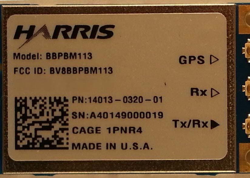
BV8BBPBM113
Apr 11, 2013Wireless Licensed Module
Equipment Class
TNB - Licensed Non-Broadcast Station Transmitter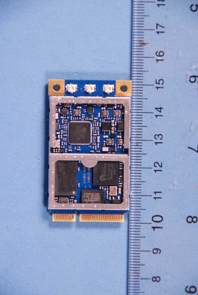
BV8BBPBM100
Feb 09, 2012700 MHz LTE Wireless Module
Equipment Class
TNB - Licensed Non-Broadcast Station Transmitter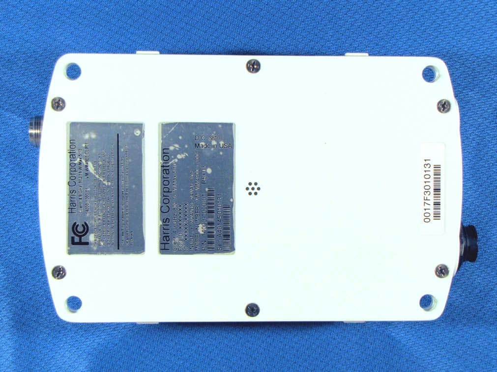
BV8WM4900CL
Nov 21, 2010Client 4.9 GHz 802.16 VBB 5/10
Equipment Class
TNB - Licensed Non-Broadcast Station Transmitter
BV8VIDA-BB-CL
Apr 11, 2007VIDA Broadband High Power Client
Equipment Class
TNB - Licensed Non-Broadcast Station Transmitter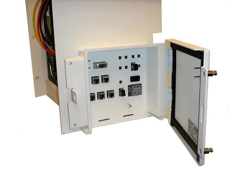
BV8CS900
Apr 08, 2007OpenSky 900 MHz Cell Site
Equipment Class
TNB - Licensed Non-Broadcast Station Transmitter