BV8VMXBAVIDAMAX Base Station
Harris Corporation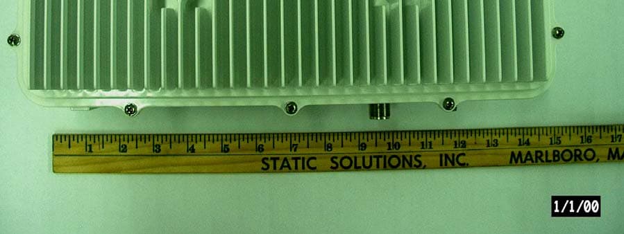
Click to zoom
Application Details
- Equipment Class
- TNB - Licensed Non-Broadcast Station Transmitter
- Date of Grant
- Jul 25, 2006
- Application Purpose
- Original Equipment
- Date of Application
- Jul 25, 2006
- Equipment Note
- VIDAMAX Base Station
- Frequency Range
- 4940.00000000 - 4990.00000000
- Company
- Harris Corporation
- Country
- United States
Documents & Files
Document Text
Text extracted from the exhibit documents filed with the FCC. Open a document above to read the original.
Users Manual
Rhein Tech Laboratories, Inc. Client: M/A-Com, Inc. 360 Herndon Parkway Model: VIDA MAX Base Station Suite 1400 Standard: FCC Part 90 Herndon, VA 20170 FCC ID: BV8VMXBA http://www.rheintech.com Report Number: 2006072 57 of 64 Appendix J: Manual Please refer to the following pages for the installation manual and see also the separate user manual document. Installation and Configuration Manual MM-009804-001 May-06 VIDA MAX Base Station 4.9 GHz Broadband Distribution System MM-009804-001 MANUAL REVISION HISTORY REVISION DATE REASON FOR CHANGE - May 2006 Initial Release. M/A-COM Technical Publications would particularly appreciate feedback on any errors found in this document and suggestions on how the document could be improved. Submit your comments and suggestions to: Wireless Systems Business Unit fax your comments to: (434) 455-6851 M/A-COM, Inc. or Technical Publications e-mail us at: [email protected] 221 Jefferson Ridge Parkway Lynchburg, VA 24501 CREDITS NOTICE! Repairs to this equipment should be made only by an authorized service technician or facility designated by the supplier. Any repairs, alterations or substitution of recommended parts made by the user to this equipment not approved by the manufacturer could void the user’s authority to operate the equipment in addition to the manufacturer’s warranty. NOTICE! This manual covers M/A-COM, Inc. products manufactured and sold by M/A-COM, Inc. This device made under license under one or more of the following US patents: 4,590,473; 4,636,791; 5,148,482; 5,185,796; 5,271,017; 5,377,229, 5,377,229; 4,716,407; 4,972460; 5,502,767; 5,146,497; 5,164,986; 5,185,795. The voice coding technology embodied in this product is protected by intellectual property rights including patent rights, copyrights, and trade secrets of Digital Voice Systems, Inc. The user of this technology is explicitly prohibited from attempting to decompile, reverse engineer, or disassemble the Object Code, or in any way convert the Object Code into human-readable form. NOTICE! This product conforms to the European Union WEEE Directive 2002/96/EC. Do not dispose of this product in a public landfill. This product should be taken to a recycling center at the end of its life. NOTICE! The software contained in this device is copyrighted by M/A-COM, Inc. Unpublished rights are reserved under the copyright laws of the United States. This manual is published by M/A-COM, Inc., without any warranty. Improvements and changes to this manual necessitated by typographical errors, inaccuracies of current information, or improvements to programs and/or equipment, may be made by M/A-COM, Inc., at any time and without notice. Such changes will be incorporated into new editions of this manual. No part of this manual may be reproduced or transmitted in any form or by any means, electronic or mechanical, including photocopying and recording, for any purpose, without the express written permission of M/A-COM, Inc. Copyright © 2006, M/A-COM, Inc. All rights reserved. 2 MM-009804-001 TABLE OF CONTENTS Page 1 REGULATORY AND SAFETY INFORMATION ............................................................................. 7 1.1 SAFETY CONVENTIONS...................................................................................................... 7 1.2 REGULATORY ......................................................................................................................8 1.2.1 Maximum Permissible Exposure Limits.................................................................... 8 1.2.2 Determining MPE Radius ......................................................................................... 8 1.2.3 Safety Training Information .................................................................................... 10 2 SPECIFICATIONS ......................................................................................................................... 11 2.1 GENERAL SPECIFICATIONS............................................................................................. 11 2.2 TRANSMITTER ................................................................................................................... 13 2.3 RECEIVER .......................................................................................................................... 13 3 INTRODUCTION............................................................................................................................ 14 3.1 ABOUT THIS MANUAL........................................................................................................ 14 3.2 CUSTOMER SERVICE.............................................................................................................. 15 3.2.1 Technical Support................................................................................................... 15 3.2.2 Customer Resource Center .................................................................................... 15 4 DESCRIPTION............................................................................................................................... 16 4.1 VIDA MAX SYSTEM OVERVIEW ........................................................................................... 16 4.2 THE VIDA NETWORK SOLUTION ...................................................................................... 16 4.3 THE VIDA MAX NETWORK .................................................................................................... 17 4.4 VIDA MAX NETWORK COMPONENTS/FEATURES ............................................................. 18 4.5 4.9 GHZ VIDA MAX BASE STATION....................................................................................... 20 4.5.1 Summary of Key Features ...................................................................................... 21 4.6 VIDA MAX BASE STATION INTERFACES............................................................................. 22 4.6.1 Standard Base Stati…
Text truncated - open the document above for the full version.
Cover Letter(s)
Rhein Tech Laboratories, Inc. Client: M/A-Com, Inc. 360 Herndon Parkway Model: VIDA MAX Base Station Suite 1400 Standard: FCC Part 90 Herndon, VA 20170 FCC ID: BV8VMXBA http://www.rheintech.com Report Number: 2006072 50 of 64 Appendix C: Confidentiality Request Letter Please refer to the following page. M/A-COM, Inc. 221 Jefferson Ridge Parkway Lynchburg, VA 24501 Telephone: 434.455.9527 FAX: 434.455.6851 [email protected] www.macom.com June 21, 2006 American TCB, Inc. 6731 Whittier Avenue Suite C110 McLean, VA 22101 Subject: FCC ID: BV8VMXBA Original application CONFIDENTIALITY M/A-COM, Inc. wishes to submit this confidentiality letter for the record on FCC ID: BV8VMXBA 4.9 GHz base station LMR radio equipment. M/A-COM, Inc. is requesting that any schematic diagrams, parts lists, block diagrams, tune-up procedure, and operational descriptions for this submission not be made routinely available for public inspection. M/A-COM, Inc. considers the information in these exhibits to be classified as trade secrets, pursuant to 47 CFR Section 0.457 and Section 0.459 of the FCC rules. Thank you for your attention to this matter. Daryl Popowitch Regulatory Manager M/A-COM, Inc. – Lynchburg, VA
Cover Letter(s)
Rhein Tech Laboratories, Inc. Client: M/A-Com, Inc. 360 Herndon Parkway Model: VIDA MAX Base Station Suite 1400 Standard: FCC Part 90 Herndon, VA 20170 FCC ID: BV8VMXBA http://www.rheintech.com Report Number: 2006072 49 of 64 Appendix B: Agency Authorization Letter Please refer to the following page. M/A-COM, Inc. 221 Jefferson Ridge Parkway Lynchburg, VA 24501 Telephone: 434.455.9527 FAX: 434.455.6851 [email protected] www.macom.com June 21, 2006 To Whom It May Concern: The following organization is granted authority to act on M/A-COM’s behalf, to file technical reports, measurements, exhibits and forms for M/A-COM equipment with FCC ID: BV8VMXBA, 4.9 GHz VIDAMAX base station LMR radio equipment, as it applies to a new submission and EA Grant. Ms. Kathy Grzovic Rhein Tech Laboratories, Inc. 360 Herndon Parkway, Suite 1400 Herndon, VA 20170 We certify that we are not subject to denial of federal benefits, that includes FCC benefits, pursuant to Section 5301 of the Anti-Drug Abuse ACT of 1988, U.S.C.862. Further, no party, as defined in 47 CFR 1.2002(b), to the application is subject to denial of federal benefits, that includes FCC benefits. Sincerely, Daryl Popowitch Regulatory Manager
Cover Letter(s)
M/A-COM, Inc. 221 Jefferson Ridge Parkway Lynchburg, VA 24501 Telephone: 434.455.9527 FAX: 434.455.6851 [email protected] www.macom.com June 21, 2006 American TCB, Inc. 6731 Whittier Avenue Suite C110 McLean, VA 22101 Subject: FCC ID: BV8VMXBA IC: 3670A-VMXBA Original submission 4.9 GHz VIDAMAX base station. M/A-COM seeks an original Equipment Authorization Grant for its’ 4.9 GHz VIDAMAX Public Safety LMR base station radio equipment. Exhibits include photographs, schematics, parts list, block diagram, tune-up procedure, FCC Part 90 and 15 compliance verification reports, and measurement data. There is no Operator Manual with this base station as it is factory configured per customer order, installed by M/A-COM field service personnel (or M/A-COM trained customer technicians) and no user available controls or adjustments are available. Special software tools are required to make any final field settings if required. The Installation Manual includes instructions for the antenna connection, mounting, and the antenna types authorized for use, as well as unit power configurations and LAN connection. Typical application is to have the base station and antenna utility pole mounted, operating in a point-to-multipoint mode. Confidentiality letter and Rhein Tech Laboratories, Inc. agent authorization letter to act on M/A-COM’s behalf for this original submission, have been provided as exhibits as well. Thank you for your kind consideration and timely review for this new product entry to the M/A-COM Public Safety LMR product family. Sincerely, Daryl Popowitch Regulatory Manager M/A-COM, Inc. – Lynchburg, VA
Cover Letter(s)
American Telecommunications Certification Body Inc. 6731 Whittier Ave, McLean, VA 22101 July 13, 2006 RE: FCC ID: BV8VMXBA_ATCB003730 Attention: Richard McMurray I have a few comments on this Application. Please note that further comments may arise in response to answers provided to the questions below. 1. Please explain the relevance of DA-02-2138A1 (UNII peak transmit power) for use with a licensed device. Please note that the most recent interpretation from the FCC states that DA-02-2138A1is not an appropriate test method for part 90Y devices. The FCC has stated that power for part 90 Y is to be measured “using a spectrum analyzer with settings: RBW>signal BW, VBW > RBW (prefer VBW> at least 3x RBW) no averaging, "trac! e max hold." As you can see this would be a peak measurement. Please note that if the resolution bandwidth cannot be set greater than the signal bandwidth the a correction factor for resolution bandwidth must be applied. Please retest the peak transmit power in accordance with the FCC instructions above. 2. Please note that on page 22 of the test report it appears to be reporting channel power and not Power Spectral Density. Please correct as necessary or please explain how channel power meets the power spectral density requirements of 90.1215(d). 3. Please note that as the power and power spectral density do not appear to have been done correctly, the other issues in the report must be reviewed once these issues have been corrected. 4. Please note that it does not appear that the part 90yMask was done properly. Please see the document attached to the email. 5. FYI - Please note that there are currently several applications for part 90Y that are waiting response from the FCC on proper measurement methods. Dennis Ward mailto:[email protected] The items indicated above must be submitted before processing can continue on the above referenced application. Failure to provide the requested information may result in application termination. Correspondence should be considered part of the permanent submission and may be viewed from the Internet after a Grant of Equipment Authorization is issued. Please do not respond to this correspondence using the email reply button. In order for your response to be processed expeditiously, you must submit your documents through the AmericanTCB.com website. Also, please note that partial responses increase processing time and should not be submitted. Any questions about the content of this correspondence should be directed to the sender.
Cover Letter(s)
American Telecommunications Certification Body Inc. 6731 Whittier Ave, McLean, VA 22101 July 13, 2006 RE: FCC ID: BV8VMXBA_ATCB003730 Attention: Richard McMurray I have a few comments on this Application. Please note that further comments may arise in response to answers provided to the questions below. 1 Please explain the relevance of DA-02-2138A1 (UNII peak transmit power) for use with a licensed device. Please note that the most recent interpretation from the FCC states that DA-02-2138A1is not an appropriate test method for part 90Y devices. The FCC has stated that power for part 90 Y is to be measured “using a spectrum analyzer with settings: RBW>signal BW, VBW > RBW (prefer VBW> at least 3x RBW) no averaging, "trac! e max hold." As you can see this would be a peak measurement. Please note that if the resolution bandwidth cannot be set greater than the signal bandwidth the a correction factor for resolution bandwidth must be applied. Please retest the peak transmit power in accordance with the FCC instructions above. Response: Please review the revised test report uploaded with this response; retesting was done per the guidance provided. 2 Please note that on page 22 of the test report it appears to be reporting channel power and not Power Spectral Density. Please correct as necessary or please explain how channel power meets the power spectral density requirements of 90.1215(d). Response: The original test report did indicate the Power Spectral Density, however it was not clear. Please see the revised test report uploaded with this response for the Power Spectral Density on page 22, and well as beneath each test plot. 3 Please note that as the power and power spectral density do not appear to have been done correctly, the other issues in the report must be reviewed once these issues have been corrected. Response: Please see the revised test report. 4 Please note that it does not appear that the part 90yMask was done properly. Please see the document attached to the email. Response: Please see the revised test report uploaded with this response. Mask measurements were re- taken based on new power levels found, per #1 above. 5 FYI - Please note that there are currently several applications for part 90Y that are waiting Response: Noted, thank you. Dennis Ward mailto:[email protected] The items indicated above must be submitted before processing can continue on the above referenced application. Failure to provide the requested information may result in application termination. Correspondence should be considered part of the permanent submission and may be viewed from the Internet after a Grant of Equipment Authorization is issued. Please do not respond to this correspondence using the email reply button. In order for your response to be processed expeditiously, you must submit your documents through the AmericanTCB.com website. Also, please note that partial responses increase processing time and should not be submitted. Any questions about the content of this correspondence should be directed to the sender.
External Photos
Rhein Tech Laboratories, Inc. Client: M/A-Com, Inc. 360 Herndon Parkway Model: VIDA MAX Base Station Suite 1400 Standard: FCC Part 90 Herndon, VA 20170 FCC ID: BV8VMXBA http://www.rheintech.com Report Number: 2006072 63 of 64 Appendix L: External Photographs Please refer to the following pages. External Photographs Photograph 1: Top Photograph 2: Bottom Photograph 3: Front Photograph 4: Back
ID Label/Location Info
Rhein Tech Laboratories, Inc. Client: M/A-Com, Inc. 360 Herndon Parkway Model: VIDA MAX Base Station Suite 1400 Standard: FCC Part 90 Herndon, VA 20170 FCC ID: BV8VMXBA http://www.rheintech.com Report Number: 2006072 51 of 64 Appendix D: Label Information Please refer to the following pages for a label sample and a photograph of the label location. ID Label Sample ID Label Here ID Label Location
Internal Photos
Rhein Tech Laboratories, Inc. Client: M/A-Com, Inc. 360 Herndon Parkway Model: VIDA MAX Base Station Suite 1400 Standard: FCC Part 90 Herndon, VA 20170 FCC ID: BV8VMXBA http://www.rheintech.com Report Number: 2006072 64 of 64 Appendix M: Internal Photographs Please refer to the following pages. INTERNAL PHOTOGRAPHS XCVR Chassis With Cover XCVR Chassis Without Cover Digital Chassis XCVR Front View XCVR Top 1 XCVR Top 2 XCVR Back View XCVR Bottom 1 XCVR Bottom 2 Digital Top 1 Digital Top 2 Digital Top 3 Digital Top 4 Digital Bottom 1 Digital Bottom 2 Digital Bottom 3 Digital Bottom 4 Power Front View Power Back View
RF Exposure Info
Rhein Tech Laboratories, Inc. Client: M/A-Com, Inc. 360 Herndon Parkway Model: VIDA MAX Base Station Suite 1400 Standard: FCC Part 90 Herndon, VA 20170 FCC ID: BV8VMXBA http://www.rheintech.com Report Number: 2006072 48 of 64 Appendix A: RF Exposure Compliance P lease refer to the following pages. MM-009804-001 1.2 REGULATORY 1.2.1 Maximum Permissible Exposure Limits DO NOT TRANSMIT with this base station and antenna when persons are within the MAXIMUM PERMISSIBLE EXPOSURE (MPE) Radius of the antenna. The MPE Radius is the minimum distance from the antenna axis that ALL persons should maintain in order to avoid RF exposure higher than the allowable MPE level set by the FCC. FAILURE TO OBSERVE THESE LIMITS MAY ALLOW ALL PERSONS WITHIN THE MPE RADIUS TO EXPERIENCE RF RADIATION ABSORPTION, WHICH EXCEEDS THE FCC MAXIMUM PERMISSIBLE EXPOSURE (MPE) LIMIT. IT IS THE RESPONSIBILITY OF THE BASE STATION LICENSEE TO ENSURE THAT THE MAXIMUM PERMISSIBLE EXPOSURE LIMITS ARE OBSERVED AT ALL TIMES DURING BASE STATION TRANSMISSION. THE BASE STATION LICENSEE IS TO ENSURE THAT NO BYSTANDERS ARE WITHIN THE RADIUS LIMITS. 1.2.2 Determining MPE Radius THE MAXIMUM PERMISSIBLE EXPOSURE RADIUS is unique for each site and is determined based on the complete installation environment (i.e. co-location, antenna type, transmit power level, etc.). Determination of the MPE distance is the responsibility of the VIDA MAX user. Calculation of the MPE radius is required as part of the installation. The Limit for Uncontrolled Exposure Power Density (P d ) is 10 W/m 2 for fixed mounted device. The M/A-COM 4.9 GHz VIDA MAX Base Station is a fixed mounted radio. After installation and commissioning, the safe distance from the 9 dBi omni-directional antenna is greater than 20 cm (8-inches). 1.2.2.1 MPE Calculation for omni-directional Antenna This MPE Minimum Distance Calculation is based on using a 9 dBi gain omni-directional antenna mounted directly to the base station RF port. Basic M/A-COM 4.9 GHz VIDA MAX Base Station specifications: P: Maximum Peak Conducted Power = 27 dBm G: Maximum Omni Antenna Gain = 9 dBi Frequency Range = 4.94 to 4.99 GHz R: Minimum Distance between User and Antenna = 0.2 m Equation from FCC: P d = P * G / ( 4 * π * R 2 ) P d = 0.5 W * 7.94 / (4 * 3.1415926 * 0.2 2 ) = 7.89 W / m 2 < 10 W / m 2 8 MM-009804-001 The calculation indicates that the minimum 0.2 meter distance between user and the omni-directional antenna (directly mounted to the base station RF port) is required when operating the M/A-COM 4.9 GHz VIDA MAX Base Station. 1.2.2.2 MPE Calculation for Directional Antenna This MPE Minimum Distance Calculation is based on using a directional antenna with more than 9 dBi antenna gain. Basic M/A-COM 4.9 GHz VIDA MAX Base Station specifications: P: Maximum Peak Conducted Power = 27 dBm; G: Maximum Omni Antenna Gain – Cable Loss = 27 dBi – 1 dB = 26 dBi; (Use numerical G N value for the calculation ): G N = 10 ^ (G /10)); For G = 26 dBi, G N = 10 ^ (26 /10) = 398 Frequency Range = 4.94 to 4.99 GHz; R min : Minimum Distance between user and antenna to comply with FCC MPE Level (10 W / m 2 ); Equation from FCC: P d = P * G / ( 4 * π * R min 2 ) R min = SQRT( 0.5 W * G N / (4 * 3.1415926 * 10 ) )= SQRT ( 3.9789E-3 * G N ) R min = 1.26 m, for G =26 (i.e., G N = 398 ) The calculation provides guidelines for users to estimate the minimum safe distance when a high gain antenna is connected to the M/A-COM 4.9 GHz VIDA MAX Base Station. The user should always keep a safe distance from antenna greater than 20 cm or SQRT (3.9789E-3 * G N ). The following table lists the minimum distance for Different Effective Antenna Gain Levels (Antenna Gain – Feeder Cable Loss) Minimum Safe Distance Calculation Based for Directional Antennas Effective Antenna Gain (dBi) Minimum Safe Distance (Meters) Minimum Safe Distance (Feet) < 9 0.20 0.65 10 0.20 0.65 11 0.22 0.73 12 0.25 0.82 13 0.28 0.92 14 0.32 1.04 15 0.35 1.16 16 0.40 1.31 17 0.45 1.47 18 0.50 1.64 19 0.56 1.84 20 0.63 2.07 21 0.71 2.32 22 0.79 2.61 23 0.89 2.92 9 MM-009804-001 Effective Antenna Gain (dBi) Minimum Safe Distance (Meters) Minimum Safe Distance (Feet) 24 1.00 3.28 25 1.12 3.68 26 1.26 4.13 >26 Reduce Transmit Power is required by FCC 1.2.3 Safety Training Information YOUR M/A-COM VIDA MAX BASE STATION GENERATES RF ELECTRO- MAGNETIC ENERGY DURING TRANSMIT MODE. THIS BASE STATION IS DESIGNED FOR AND CLASSIFIED AS “OCCUPATIONAL USE ONLY” MEANING IT MUST BE USED ONLY IN THE COURSE OF EMPLOYMENT BY INDIVIDUALS AWARE OF THE HAZARDOUS RF ENERGY AND THE WAYS TO MINIMIZE EXPOSURE. THIS BASE STATION IS NOT INTENDED FOR USE BY THE “GENERAL POPULATION” IN AN UNCONTROLLED ENVIRONMENT. IT IS THE RESPONSIBILITY OF THE LICENSEE TO ENSURE THAT THE MAXIMUM PERMISSIBLE EXPOSURE LIMITS ARE OBSERVED AT ALL TIMES DURING TRANSMISSION. THE BASE STATION LICENSEE IS TO ENSURE THAT NO BYSTANDERS COME WITHIN THE RADIUS OF THE LIMITS When licensed by the FCC, this base station complies with the FCC RF exposure limits when persons are beyond the MPE radius of the antenna. In addition, your M/A-COM base stations installation complies with the following Standards and Guidelines with regard to RF energy and electromagnetic energy levels and evaluation of such levels for exposure to humans: FCC OET Bulletin 65 Edition 97-01 Supplement C, Evaluating Compliance with FCC Guidelines for Human Exposure to Radio Frequency Electromagnetic Fields. American National Standards Institute (C95.1 – 1992), IEEE Standard for Safety Levels with Respect to Human Exposure to Radio Frequency Electromagnetic Fields, 3 kHz to 300 GHz. American National Standards Institute (C95.3 – 1992), IEEE Recommended Practice for the Measurement of Potentially Hazardous Electromagnetic Fields – RF and Microwave. CAUTION To ensure that your exposure to RF electromagnetic energy is within the FCC allowable limits for occupational use, do not operate the base station in a manner that would create an MPE distance in exces…
Text truncated - open the document above for the full version.
Test Report
Engineering and Testing for EMC and Safety Compliance 360 Herndon Parkway Suite 1400 Herndon, VA 20170 Ph: 703-689-0368 Fax: 703-689-2056 C C e e r r t t i i f f i i c c a a t t i i o o n n R R e e p p o o r r t t M/A-Com, Inc. 221 Jefferson Ridge Parkway Lynchburg, VA 24501 Daryl Popowitch Phone: (434) 455-9527 E-Mail: [email protected] Model: VIDA MAX Base Station 4940 – 4990 MHz FCC ID: BV8VMXBA July 25, 2006 Standards Referenced for this Report Part 2: 2005 Frequency Allocations and Radio Treaty Matters; General Rules and Regulations Part 90: 2005 Private Land Mobile Radio Services ANSI/TIA-603-C-2004 Land Mobile FM or PM Communications Equipment Measurement and Performance Standards ANSI/TIA/EIA – 102.CAAA; 2002 Digital C4FM/CQPSK Transceiver Measurement Methods Frequency Range Measured Peak Transmit Power (W) Conducted Measured Frequency Tolerance (ppm) Emission Designator 4940-4990 MHz 0.26 1.4 5M0X7D Report Prepared by Test Engineer: Daniel Biggs Document Number: 2006072 This report may not be reproduced, except in full, without the written approval of Rhein Tech Laboratories, Inc. Test results relate only to the product tested. Rhein Tech Laboratories, Inc. Client: M/A-Com, Inc. 360 Herndon Parkway Model: VIDA MAX Base Station Suite 1400 Standard: FCC Part 90 Herndon, VA 20170 FCC ID: BV8VMXBA http://www.rheintech.com Report Number: 2006072 2 of 64 Table of Contents 1 General Information................................................................................................................................................... 5 1.1 Test Facility.............................................................................................................................................................................5 1.2 Related Submittal(s)/Grant(s)..................................................................................................................................................5 2 Tested System Details............................................................................................................................................... 6 3 FCC Rules and Regulations Part 2 §2.1033(c)(8) Voltages and Currents Through The Final Amplifying Stage....... 7 4 FCC Rules and Regulations Part 90 §90.1215(a) and Part 2 §2.1046(a): Peak Output Power................................ 8 4.1 Test Procedure ........................................................................................................................................................................8 4.2 Test Data .................................................................................................................................................................................9 5 FCC Rules and Regulations Part 90 §90.1215(a): Peak Power Spectral Density.................................................. 21 5.1 Test Procedure ......................................................................................................................................................................21 5.2 Test Data ...............................................................................................................................................................................22 6 FCC Rules and Regulations Part 90 §90.210(m) and Part 2 §2.1049: Occupied Bandwidth (Emissions Masks) and ducted Spurious Emissions...............................................................................................................................34 Con 6.1 Test Procedure ......................................................................................................................................................................34 6.2 In Band Spurious Test Data..................................................................................................................................................35 6.3 Out of Band Spurious Test Data...........................................................................................................................................39 7 FCC Rules and Regulations Part 90 §90.210(l) and Part 2 §2.1053(a): Field Strength of Spurious Radiation....... 42 7.1 Test Procedure ......................................................................................................................................................................42 7.2 Test Data ...............................................................................................................................................................................43 7.2.1 CFR 47 Part 90.210 Requirements..................................................................................................................................43 8 FCC Rules and Regulation Part 90 §90.213(a) and Part 2 §2.1055: Frequency Stability...................................... 45 8.1 Test Procedure ......................................................................................................................................................................45 8.2 Frequency Stability Test Data...............................................................................................................................................46 8.2.1 Frequency Stability/Temperature Variation......................................................................................................................46 8.2.2 Frequency Stability/Voltage Variation..............................................................................................................................46 9 Conclusion............................................................................................................................................................... 47 Rhein Tech Laboratories, Inc. Client: M/A-Com, Inc. 360 Herndon Parkway Model: VIDA MAX Base Station Suite 1400 Standard: FCC Part 90 Herndon, VA 20170 FCC ID: BV8VMXBA http://www.rheintech.com Report Number: 2006072 3 of 64 Table of Tables Table 2-1: Equipment…
Text truncated - open the document above for the full version.
Contact Information
Applicant
Thomas Camper, Jr.(Regulatory Manager)
Technical Specifications
| # | Rule Parts | Frequency Range | Power Output | Emission | Tolerance |
|---|---|---|---|---|---|
| 1 | 90 | 4.94 GHz - 4.99 GHz | 256.00 mW | 5M0X7D | 1.4000000000 ppm |
Other Applications from Harris Corporation
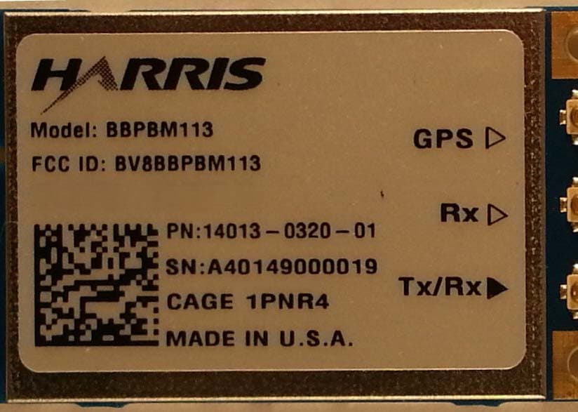
BV8BBPBM113
Apr 11, 2013Wireless Licensed Module
Equipment Class
TNB - Licensed Non-Broadcast Station Transmitter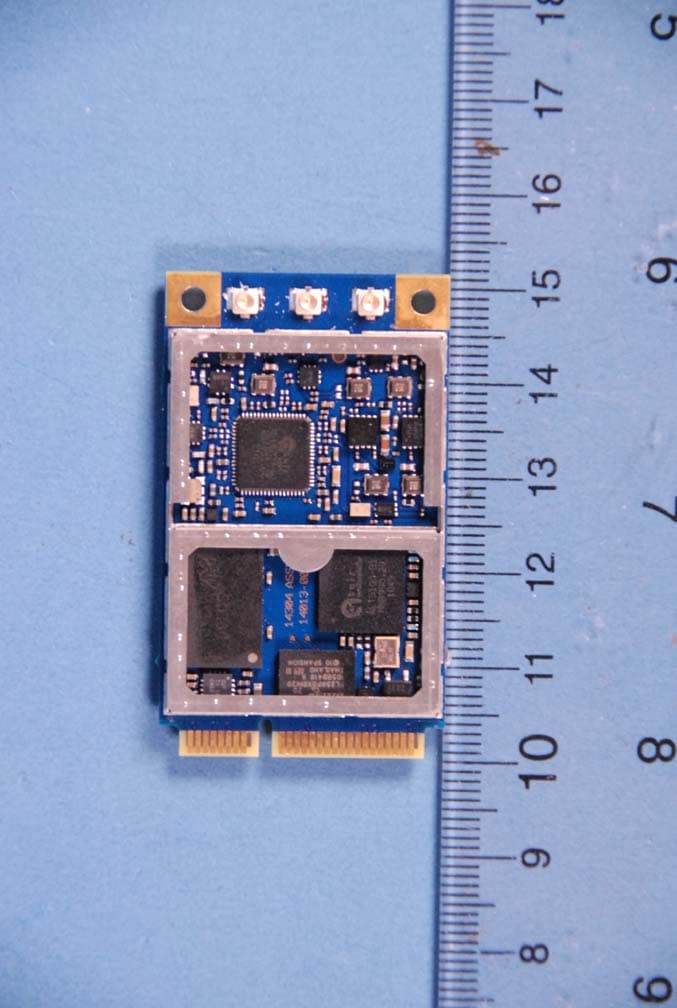
BV8BBPBM100
Feb 09, 2012700 MHz LTE Wireless Module
Equipment Class
TNB - Licensed Non-Broadcast Station Transmitter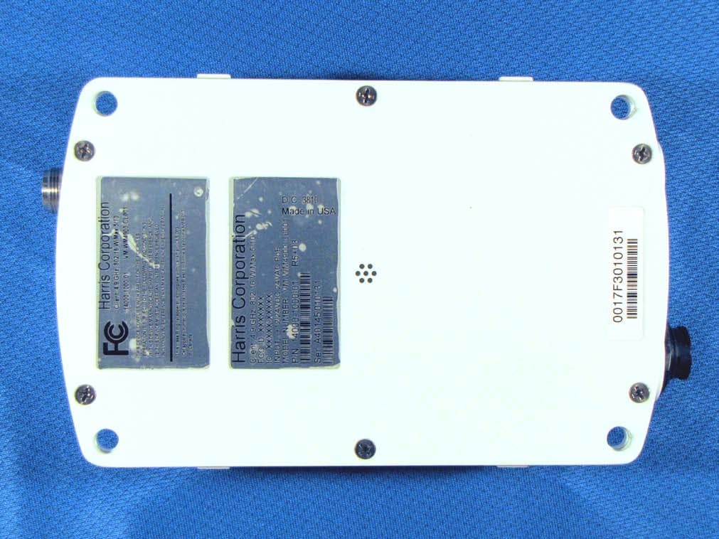
BV8WM4900CL
Nov 21, 2010Client 4.9 GHz 802.16 VBB 5/10
Equipment Class
TNB - Licensed Non-Broadcast Station Transmitter
BV8VIDA-BB-CL
Apr 11, 2007VIDA Broadband High Power Client
Equipment Class
TNB - Licensed Non-Broadcast Station Transmitter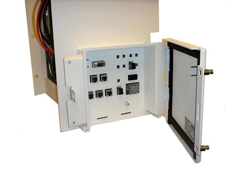
BV8CS900
Apr 08, 2007OpenSky 900 MHz Cell Site
Equipment Class
TNB - Licensed Non-Broadcast Station Transmitter