BV8VTAC800800 MHz Vehicular Tactical Assistance Mobile Radio
Harris Corporation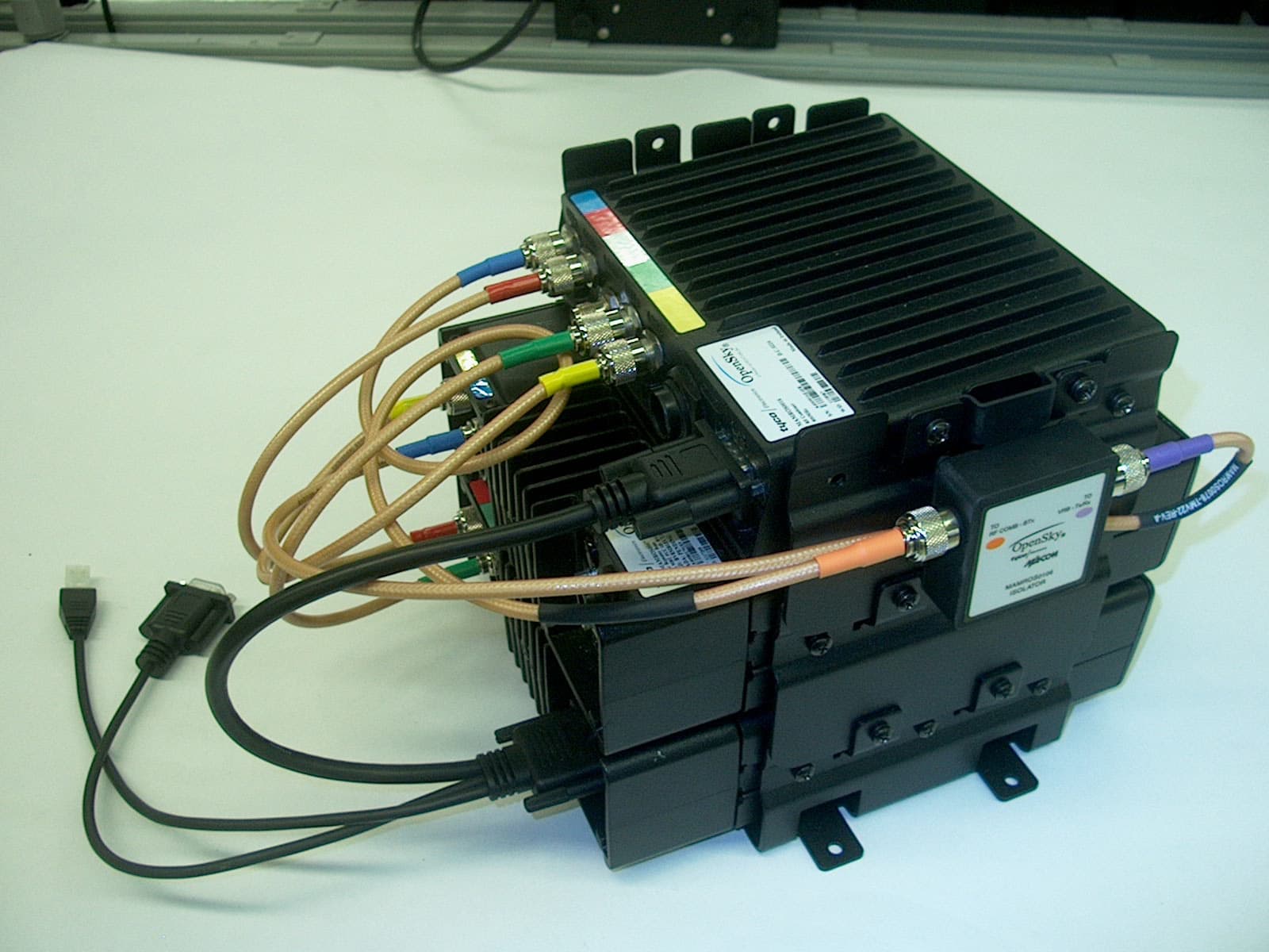
Click to zoom
Application Details
- Equipment Class
- TNB - Licensed Non-Broadcast Station Transmitter
- Date of Grant
- May 25, 2005
- Application Purpose
- Original Equipment
- Date of Application
- May 25, 2005
- Equipment Note
- 800 MHz Vehicular Tactical Assistance Mobile Radio
- Frequency Range
- 851.00000000 - 869.00000000
- Company
- Harris Corporation
- Country
- United States
Documents & Files
Document Text
Text extracted from the exhibit documents filed with the FCC. Open a document above to read the original.
Users Manual
Operator’s Manual MM102014V1 Rev. E, May-05 M-803 Digital Mobile Radio with Vehicular Tactical Network (V-TAC) 2 MANUAL REVISION HISTORY REV DATE REASON FOR CHANGE R1A Jul. 2003 Original Release. B Mar. 2004 Replaced “blasting caps” hazard information with OSHA-standard blasting caps hazard information. C Nov. 2004 Updated safety information, personality section, menu structure figure, log-in and log-off sections, radio tones section, stealth mode section, V-TAC SOI mode section, selective call section, emergency communications section, and DTMF microphone section. Added information on telephone interconnect calls, GPS coordinates display, V-TAC XCOV-TG mode operations, and engineering data display. D Dec. 2004 Updated emergency communications and manual encryption sections. Separated selective alert subsection from selective call section. E May 2005 Modifed MPE information for FCC compliance. M/A-COM Technical Publications would particularly appreciate feedback on any errors found in this document and suggestions on how the document could be improved. Submit your comments and suggestions to: Wireless Systems Business Unit or fax your comments to: (434) 455-6851 M/A-COM, Inc. Technical Publications or e-mail us at: [email protected] 221 Jefferson Ridge Parkway Lynchburg, VA 24501 CREDITS This device is made under license under one or more of the following US patents: 4,590,473; 4,636,791; 5,148,482; 5,185,796; 5,271,017; 5,377,229; 4,716,407; 4,972,460; 5,502,767; 5,146,497; 5,164,986; 5,185,795. The voice coding technology embodied in this product is protected by intellectual property rights including patent rights, copyrights, and trade secrets of Digital Voice Systems, Inc. The user of this technology is explicitly prohibited from attempting to decompile, reverse engineer, or disassemble the Object Code, or in any other way convert the Object Code into human-readable form. OpenSky is a registered trademark of M/A-COM, Inc. All other brand and product names are trademarks, registered trademarks or service marks of their respective holders. NOTICE! This manual covers M/A-COM products manufactured and sold by M/A-COM, Inc. Repairs to this equipment should be made only by an authorized service technician or facility designated by the supplier. Any repairs, alterations or substitutions of recommended parts made by the user to this equipment not approved by the manufacturer could void the user's authority to operate the equipment in addition to the manufacturer's warranty. This manual is published by M/A-COM, Inc., without any warranty. Improvements and changes to this manual necessitated by typographical errors, inaccuracies of current information, or improvements to programs and/or equipment, may be made by M/A-COM, Inc., at any time and without notice. Such changes will be incorporated into new editions of this manual. No part of this manual may be reproduced or transmitted in any form or by any means, electronic or mechanical, including photocopying and recording, for any purpose, without the express written permission of M/A-COM, Inc. Copyright © 2003-2005 M/A-COM, Inc. All rights reserved. 3 TABLE OF CONTENTS Page 1 SAFETY INFORMATION ......................................................................6 1.1 OCCUPATIONAL SAFETY GUIDELINES AND SAFETY TRAINING INFORMATION.............................................................8 1.2 COMMON HAZARDS.......................................................................9 2 PRODUCT DESCRIPTION ..................................................................10 2.1 VOICE OPERATION .......................................................................11 2.2 DATA OPERATION ........................................................................11 2.3 REMOTE CONTROL HEAD OPERATION ...................................11 2.4 INTERCOM OPERATION...............................................................12 2.5 V-TAC OPERATION .......................................................................12 2.6 PERSONALITY................................................................................12 2.6.1 Profiles.............................................................................12 2.6.2 Talk Groups .....................................................................13 2.7 GPS OPTION....................................................................................13 2.8 FRONT PANEL ................................................................................14 2.9 M-803 REAR PANEL.......................................................................15 2.10 CONTROL HEAD REAR PANEL...................................................16 2.11 V-TAC REAR PANEL .....................................................................17 3 OPERATION ..........................................................................................18 3.1 FRONT PANEL COMPONENTS OVERVIEW ..............................18 3.2 DISPLAY OVERVIEW....................................................................20 3.2.1 Network Connectivity Icon ..............................................20 3.2.2 Volume Level Icon ..........................................................20 3.2.3 Display’s Top Line..........................................................21 3.2.4 Display’s Bottom Line .....................................................21 3.2.5 Dwell Display ..................................................................21 3.2.6 Menu Display and Control Area ......................................24 3.2.7 Dwell Display User-Selectable ........................................25 3.3 BASIC RADIO OPERATION ..........................................................25 3.3.1 Turning the Radio On ......................................................25 3.3.2 Self-Test...........................................................................28 3.3.3 “Logging In” to the Network ...........................................28 3.3.4 Logging Off the Netwo…
Text truncated - open the document above for the full version.
Cover Letter(s)
M/A-COM, Inc. 221 Jefferson Ridge Parkway Lynchburg, VA 24501 Telephone: 434.455.9527 FAX: 434.455.6851 [email protected] www.macom.com May 9, 2005 American TCB, Inc. 6731 Whittier Avenue Suite C110 McLean, VA 22101 Subject: FCC ID: BV8VTAC800 New Equipment Authorization Grant CONFIDENTIALITY M/A-COM, Inc. wishes to submit this confidentiality letter for the exhibits submitted on FCC ID: BV8VTAC800. M/A-COM, Inc. is requesting that schematic diagrams, operational description, block diagrams, factory calibration, and part lists for this new Equipment Authorization, not be made routinely available for public inspection. M/A-COM, Inc. considers the information in these exhibits to be classified as trade secrets, pursuant to 47 CFR Section 0.457 and Section 0.459 of the FCC rules. Thank you for your attention to this matter. Daryl Popowitch Regulatory Manager Engineering Project Manager M/A-COM, Inc. – Lynchburg, VA
Cover Letter(s)
M/A-COM, Inc. 221 Jefferson Ridge Parkway Lynchburg, VA 24501 Telephone: 434.455.9527 FAX: 434.455.6851 [email protected] www.macom.com May 9, 2005 To Whom It May Concern: The following organization is granted authority to act on M/A-COM’s behalf, to file technical reports, measurements, and forms for M/A-COM equipment with FCC ID: BV8VTAC800, Vehicular Tactical Unit mobile radio, as it applies to a new equipment Equipment Authorization Grant. Ms. Kathy Grzovic Rhein Tech Laboratories, Inc. 360 Herndon Parkway, Suite 1400 Herndon, VA 20170 We certify that we are not subject to denial of federal benefits, that includes FCC benefits, pursuant to Section 5301 of the Anti-Drug Abuse ACT of 1988, U.S.C.862. Further, no party, as defined in 47 CFR 1.2002(b), to the application is subject to denial of federal benefits, that includes FCC benefits. Sincerely, Daryl Popowitch Regulatory Manager, Engineering Project Manager M/A-COM, Inc. – Lynchburg, VA
Cover Letter(s)
American Telecommunications Certification Body Inc. 6731 Whittier Ave, McLean, VA 22101 May 17, 2005 RE: FCC ID: BV8VTAC800_ATCB002435 Attention: Rick McMurray / Kathy Grzovic I have a few comments on this Application. Please note that further comments may arise in response to answers provided to the questions below. 1. Please note that the manual provides tables that indicate the device can be used in uncontrolled environments (see table 1-1 page 6 of the installation manual). The warning label states the device is only for controlled environments. Please also note that the safe distances mentioned in the MPE report are not the same as specified in the installation manual. Please explain why. 2. Please provide the test report for the application package. The report provided under Test Report, is a duplicate of the MPE report Dennis Ward mailto:[email protected] The items indicated above must be submitted before processing can continue on the above referenced application. Failure to provide the requested information may result in application termination. Correspondence should be considered part of the permanent submission and may be viewed from the Internet after a Grant of Equipment Authorization is issued. Please do not respond to this correspondence using the email reply button. In order for your response to be processed expeditiously, you must submit your documents through the AmericanTCB.com website. Also, please note that partial responses increase processing time and should not be submitted. Any questions about the content of this correspondence should be directed to the sender.
Cover Letter(s)
American Telecommunications Certification Body Inc. 6731 Whittier Ave, McLean, VA 22101 May 22, 2005 Supplemental comments RE: FCC ID: BV8VTAC800_ATCB002435 Attention: Rick McMurray / Kathy Grzovic I have a few comments on this Application. Please note that further comments may arise in response to answers provided to the questions below. 1. Please note that the 731 states the power of this device is 24.6W. Pages 1 and 12 of the report also state 24.6W. However, the spurious emissions data shown on page 43 of the report state that the conducted high power is only 15.14W (which appears to be from the occupied bandwidth plots). Please note that radiated ERP limits for spurious emissions are to be compared to the measured ERP power measurements of the fundamental and not conducted power measurements or occupied bandwidth measurement data as would be indicated in the report. While the end result of the formula 43 + 10log(P) is -13dBm for all of the above instances, -13dBm is not the limit to which measurements are being made. As it s the dBc values that are stated in the report, these values should reflect the correct units etc. The report references incorrect dBc limits and does not agree with the conducted power measurements reported on page 1 and 12 of the report nor is there ERP antenna substitution measurements to support dBc values for radiated spurious emissions. Please explain and please compare the radiated spurious ERP emissions using the proper and correct power levels and values. 2. Please note that the manual separation distances listed do not agree with the MPE report distances. Please address the inconsistent MPE distances in the various documents. Please be consistent in reporting MPE. Dennis Ward mailto:[email protected] The items indicated above must be submitted before processing can continue on the above referenced application. Failure to provide the requested information may result in application termination. Correspondence should be considered part of the permanent submission and may be viewed from the Internet after a Grant of Equipment Authorization is issued. Please do not respond to this correspondence using the email reply button. In order for your response to be processed expeditiously, you must submit your documents through the AmericanTCB.com website. Also, please note that partial responses increase processing time and should not be submitted. Any questions about the content of this correspondence should be directed to the sender.
Cover Letter(s)
M/A-COM, Inc. 221 Jefferson Ridge Parkway Lynchburg, VA 24501 Telephone: 434.455.9527 FAX: 434.455.6851 [email protected] www.macom.com May 23, 2005 American TCB, Inc. 6731 Whittier Avenue Suite C110 McLean, VA 22101 Subject: FCC ID: BV8VTAC800 M/A-COM has received questions concerning manual content for the above referenced request for original Equipment Authorization Grant. Questions and comments are presented below: 1. Please note that the manual provides tables that indicate the device can be used in uncontrolled environments (see table 1-1 page 6 of the installation manual). The warning label states the device is only for controlled environments. Response: Both the Operator’s and Installation manuals have been revised to show Controlled environment values only. Updated manuals are supplied with this letter response. 2. Please also note that the safe distances mentioned in the MPE report are not the same as specified in the installation manual. Please explain why. Response: Both the Operator’s and Installation manuals have been revised to show Controlled environment distances, consistent with the MPE report. Updated manuals are supplied with this letter response. Finally, the 0dBd vertical antenna has been shown as having the same MPE distance as the 3.5dBd antenna, a very conservative assumption. Testing was bypassed and the lumped listing approach used, due to the small incremental distance difference and the cost associated with testing multiple antenna variants. Thank you for your kind consideration and timely review of these responses. Sincerely, Daryl Popowitch Regulatory Manager, Engineering Project Manager M/A-COM, Inc. – Lynchburg, VA
Cover Letter(s)
American Telecommunications Certification Body Inc. 6731 Whittier Ave, McLean, VA 22101 May 22, 2005 Supplemental comments RE: FCC ID: BV8VTAC800_ATCB002435 Attention: Rick McMurray / Kathy Grzovic I have a few comments on this Application. Please note that further comments may arise in response to answers provided to the questions below. 1. Please note that the 731 states the power of this device is 24.6W. Pages 1 and 12 of the report also state 24.6W. However, the spurious emissions data shown on page 43 of the report state that the conducted high power is only 15.14W (which appears to be from the occupied bandwidth plots). Please note that radiated ERP limits for spurious emissions are to be compared to the measured ERP power measurements of the fundamental, and not conducted power measurements or occupied bandwidth measurement data, as would be indicated in the report. While the end result of the formula 43 + 10log(P) is -13 dBm for all of the above instances, -13dBm is not the limit to which measurements are being made. As it is the dBc values that are stated in the report, these values should reflect the correct units etc. The report references incorrect dBc limits and does not agree with the conducted power measurements reported on page 1 and 12 of the report nor is there ERP antenna substitution measurements to support dBc values for radiated spurious emissions. Please explain and please compare the radiated spurious ERP emissions using the proper and correct power levels and values. Response : Regarding using ERP vs conducted measurements for the spurious comparison, per previous certifications (see correspondence for ATH2425170) and a telephone call discussing this subject with you, Bill Graff and myself (Rick McMurray) on July 15, 2004, we kindly request that we leave the comparison against the conducted power. Regarding the conducted power values on pages 41 and 42 not matching the power reported on pages 1 and 12, the EUT is comprised of two individual transmitters joined through a combiner. In worst case operation, both transmitters can transmit simultaneously, but always on separate frequencies. For the spurious data presented on pages 41 and 42, the transmitters were operating simultaneously (to represent worst case), but the emissions from only one of the transmitters was individually evaluated in each case (since we were not only focusing on the spurious emissions, but from the harmonics generated by the specific transmitter being investigated). We chose this approach as it puts more stringent limits on the emissions from each of the transmitters while operating simultaneously (as opposed to using the combined total power as reported on pages 1 and 12). 2. Please note that the manual separation distances listed do not agree with the MPE report distances. Please address the inconsistent MPE distances in the various documents. Please be consistent in reporting MPE. Response : Please refer to the revised installation and operations manuals uploaded with this response. Dennis Ward mailto:[email protected] The items indicated above must be submitted before processing can continue on the above referenced application. Failure to provide the requested information may result in application termination. Correspondence should be considered part of the permanent submission and may be viewed from the Internet after a Grant of Equipment Authorization is issued. Please do not respond to this correspondence using the email reply button. In order for your response to be processed expeditiously, you must submit your documents through the AmericanTCB.com website. Also, please note that partial responses increase processing time and should not be submitted. Any questions about the content of this correspondence should be directed to the sender.
Cover Letter(s)
American Telecommunications Certification Body Inc. 6731 Whittier Ave, McLean, VA 22101 May 17, 2005 RE: FCC ID: BV8VTAC800_ATCB002435 Attention: Rick McMurray / Kathy Grzovic I have a few comments on this Application. Please note that further comments may arise in response to answers provided to the questions below. 1. Please note that the manual provides tables that indicate the device can be used in uncontrolled environments (see table 1-1 page 6 of the installation manual). The warning label states the device is only for controlled environments. Please also note that the safe distances mentioned in the MPE report are not the same as specified in the installation manual. Please explain why. Response : The device is for use in controlled environments, not uncontrolled environments. Please refer to the revised installation manual and operator’s manual, uploaded with this response, for consistent environment references and safe distances. 2. Please provide the test report for the application package. The report provided under Test Report, is a duplicate of the MPE report. Response : The report was previously uploaded immediately. Dennis Ward mailto:[email protected] The items indicated above must be submitted before processing can continue on the above referenced application. Failure to provide the requested information may result in application termination. Correspondence should be considered part of the permanent submission and may be viewed from the Internet after a Grant of Equipment Authorization is issued. Please do not respond to this correspondence using the email reply button. In order for your response to be processed expeditiously, you must submit your documents through the AmericanTCB.com website. Also, please note that partial responses increase processing time and should not be submitted. Any questions about the content of this correspondence should be directed to the sender.
External Photos
Rhein Tech Laboratories, Inc. Client: M/A-COM, Inc. 360 Herndon Parkway Model: OpenSky M-803 V-TAC Suite 1400 Standards: FCC Part 90 & IC RSS-119 Herndon, VA 20170 Report Number: 2005029 http://www.rheintech.com Date: May 16, 2005 76 of 87 APPENDIX K: EXTERNAL PHOTOGRAPHS PHOTOGRAPH 6: VTAC STACK-UP FRONT VIEW Rhein Tech Laboratories, Inc. Client: M/A-COM, Inc. 360 Herndon Parkway Model: OpenSky M-803 V-TAC Suite 1400 Standards: FCC Part 90 & IC RSS-119 Herndon, VA 20170 Report Number: 2005029 http://www.rheintech.com Date: May 16, 2005 77 of 87 PHOTOGRAPH 7: VTAC STACK-UP REAR VIEW Rhein Tech Laboratories, Inc. Client: M/A-COM, Inc. 360 Herndon Parkway Model: OpenSky M-803 V-TAC Suite 1400 Standards: FCC Part 90 & IC RSS-119 Herndon, VA 20170 Report Number: 2005029 http://www.rheintech.com Date: May 16, 2005 78 of 87 PHOTOGRAPH 8: VTAC FULLY ASSEMBLED
ID Label/Location Info
Rhein Tech Laboratories, Inc. Client: M/A-COM, Inc. 360 Herndon Parkway Model: OpenSky M-803 V-TAC Suite 1400 Standards: FCC Part 90 & IC RSS-119 Herndon, VA 20170 Report Number: 2005029 http://www.rheintech.com Date: May 31, 2005 71 of 87 APPENDIX H: LABEL AND LOCATION PHOTOGRAPH 1: FCC ID & IC ID LABEL SAMPLE PHOTOGRAPH 2: PART 15 AND RF WARNING LABELS Rhein Tech Laboratories, Inc. Client: M/A-COM, Inc. 360 Herndon Parkway Model: OpenSky M-803 V-TAC Suite 1400 Standards: FCC Part 90 & IC RSS-119 Herndon, VA 20170 Report Number: 2005029 http://www.rheintech.com Date: May 31, 2005 72 of 87 PHOTOGRAPH 3: LABEL PLACEMENT ON VTAC STACKUP REAR FCC ID Label Pt. 15 and RF Warning Labels
Internal Photos
Rhein Tech Laboratories, Inc. Client: M/A-COM, Inc. 360 Herndon Parkway Model: OpenSky M-803 V-TAC Suite 1400 Standards: FCC Part 90 & IC RSS-119 Herndon, VA 20170 Report Number: 2005029 http://www.rheintech.com Date: May 16, 2005 79 of 87 APPENDIX L: INTERNAL PHOTOGRAPHS PHOTOGRAPH 9: RADIO TOP VIEW WITH SHIELDS Rhein Tech Laboratories, Inc. Client: M/A-COM, Inc. 360 Herndon Parkway Model: OpenSky M-803 V-TAC Suite 1400 Standards: FCC Part 90 & IC RSS-119 Herndon, VA 20170 Report Number: 2005029 http://www.rheintech.com Date: May 16, 2005 80 of 87 PHOTOGRAPH 10: RADIO TOP VIEW WITHOUT SHIELDS Rhein Tech Laboratories, Inc. Client: M/A-COM, Inc. 360 Herndon Parkway Model: OpenSky M-803 V-TAC Suite 1400 Standards: FCC Part 90 & IC RSS-119 Herndon, VA 20170 Report Number: 2005029 http://www.rheintech.com Date: May 16, 2005 81 of 87 PHOTOGRAPH 11: RADIO BOTTOM VIEW WITH GPS UNIT
Internal Photos
Rhein Tech Laboratories, Inc. Client: M/A-COM, Inc. 360 Herndon Parkway Model: OpenSky M-803 V-TAC Suite 1400 Standards: FCC Part 90 & IC RSS-119 Herndon, VA 20170 Report Number: 2005029 http://www.rheintech.com Date: May 16, 2005 82 of 87 PHOTOGRAPH 12: HPA PCB TOP VIEW Rhein Tech Laboratories, Inc. Client: M/A-COM, Inc. 360 Herndon Parkway Model: OpenSky M-803 V-TAC Suite 1400 Standards: FCC Part 90 & IC RSS-119 Herndon, VA 20170 Report Number: 2005029 http://www.rheintech.com Date: May 16, 2005 83 of 87 PHOTOGRAPH 13: HPA PCB BOTTOM VIEW Rhein Tech Laboratories, Inc. Client: M/A-COM, Inc. 360 Herndon Parkway Model: OpenSky M-803 V-TAC Suite 1400 Standards: FCC Part 90 & IC RSS-119 Herndon, VA 20170 Report Number: 2005029 http://www.rheintech.com Date: May 16, 2005 84 of 87 PHOTOGRAPH 14: PK PCB TOP VIEW
Internal Photos
Rhein Tech Laboratories, Inc. Client: M/A-COM, Inc. 360 Herndon Parkway Model: OpenSky M-803 V-TAC Suite 1400 Standards: FCC Part 90 & IC RSS-119 Herndon, VA 20170 Report Number: 2005029 http://www.rheintech.com Date: May 16, 2005 85 of 87 PHOTOGRAPH 15: PK PCB BOTTOM VIEW Rhein Tech Laboratories, Inc. Client: M/A-COM, Inc. 360 Herndon Parkway Model: OpenSky M-803 V-TAC Suite 1400 Standards: FCC Part 90 & IC RSS-119 Herndon, VA 20170 Report Number: 2005029 http://www.rheintech.com Date: May 16, 2005 86 of 87 PHOTOGRAPH 16: XCVR PCB TOP VIEW Rhein Tech Laboratories, Inc. Client: M/A-COM, Inc. 360 Herndon Parkway Model: OpenSky M-803 V-TAC Suite 1400 Standards: FCC Part 90 & IC RSS-119 Herndon, VA 20170 Report Number: 2005029 http://www.rheintech.com Date: May 16, 2005 87 of 87 PHOTOGRAPH 17: XCVR PCB BOTTOM VIEW
RF Exposure Info
Engineering and Testing for EMC and Safety Compliance 360 Herndon Parkway, Suite 1400 Herndon, VA 20170 Phone 703 689-0368 Fax 703 689-2056 RF Exposure Assessment for Controlled and Uncontrolled Environments Maximum Permissible Exposure Testing for M/A-COM, Inc. Model: OpenSky M-803 VTAC 800 MHz Mobile Radio FCC ID: BV8VTAC800 M/A-COM, Inc. 221 Jefferson Ridge Parkway Lynchburg, VA 24501 USA Telephone: 434-455-9527 Contact: Daryl Popowitch April 13, 2005 Report Prepared By: Galina Yushina, Test Engineer Report Number: 2005029-004 Rev 0.02 The test results reported in this document relate only to the item that was tested. No part of this report may be reproduced, except in full, without written approval of M/A-Com, Inc. and Rhein Tech Laboratories, Inc. Engineering and Testing for EMC and Safety Compliance 360 Herndon Parkway, Suite 1400 Herndon, VA 20170 Phone 703 689-0368 Fax 703 689-2056 CONFORMANCE STATEMENT Standard(s) to which conformity is declared: STANDARDS AND OTHER APPLICABLE DOCUMENTS ENVIRONMENTAL PHENOMENA • FCC OET Bulletin 65 • FCC 47 CFR, Paragraphs 1.1310 and 2.1091 • TCB Training Material Maximum Permissible Exposure (MPE) for Controlled and Uncontrolled Environment Device for which conformity is declared: Manufacturer’s Name M/A-COM, Inc. Manufacturer’s Address 221 Jefferson Ridge Parkway Lynchburg, VA 24501 USA Trade Name OpenSky V-TAC (Vehicular Tactical Network) 800 MHz Mobile Radio Device Classification Licensed Non-Broadcast Transceiver Device Type Mobile 800 MHz Radio Transceiver with Vehicle Rooftop Antenna Model Number M-803 VTAC Serial Numbers 03061-3J04-00763 (VRB transceiver); 03051-2K07-00197 (VRM transceiver) FCC ID BV8VTAC800 TX Frequency Ranges 806 – 824 MHz and 851 – 869 MHz RF Max Power Rating 24.6 Watts TX Duty Cycle 50% Antenna(s) to be used with the device Rooftop mount antenna, model ASPA 1850, 5/8 wave over 1/4 wave, 3dBd (5 dBi), vertical ground plane Year of Manufacture 2005 We, the undersigned, hereby declare that the equipment specified above conforms to the MPE limits for controlled and uncontrolled environments required by the above identified standards at the distance referenced as the safe distance in the attached test report. No modifications were made during testing to the equipment in order to comply with the requirements of the standards. Test Personnel: Galina Yushina March 31, 2005 Test Engineer Signature Date Richard B. McMurray, P.E. March 31, 2005 Supervising Engineer Signature Date Rhein Tech Laboratories, Inc. Client: M/A-COM, Inc. 360 Herndon Parkway, Suite 1400 Model: M-803 VTAC Herndon, VA 20170 Report: 2005029-004 www.rheintech.com TABLE OF CONTENTS 1 MPE MEASUREMENTS AND FCC REGULATIONS............................................................................... 4 2 IDENTIFICATION OF THE EUT ............................................................................................................... 4 3 MODIFICATIONS ..................................................................................................................................... 5 4 TEST LABORATORY ............................................................................................................................... 5 5 TEST EQUIPMENT, ACCESSORIES AND TEST SET UP ..................................................................... 9 6 MPE LIMITS............................................................................................................................................ 12 7 STANDARD TEST CONDITIONS AND ENGINEERING PRACTICES ................................................. 13 8 MEASUREMENT PROCEDURE ............................................................................................................ 13 9 TEST RESULTS ..................................................................................................................................... 14 10 CONCLUSION .................................................................................................................................... 15 Rhein Tech Laboratories, Inc. Client: M/A-COM, Inc. 360 Herndon Parkway, Suite 1400 Model: M-803 VTAC Herndon, VA 20170 Report: 2005029-004 www.rheintech.com Page 4 of 15 1 MPE MEASUREMENTS AND FCC REGULATIONS This test report presents the results of Maximum Permissible Exposure (MPE) 1 testing performed on the M/A-Com, Inc. Model OpenSky M-803 VTAC (Vehicular Tactical Unit) 800 MHz Radio. The tests were performed in accordance with the FCC Rules and Regulations: FCC OET Bulletin 65: “Evaluating Compliance with FCC-Specified Guidelines for Human Exposure to Radio Frequency Radiation”, Subpart I of Part 1 of 47 CFR FCC Rules and Regulations: “Procedures Implementing the National Environmental Policy Act of 1969”, Subpart J of Part 2 of 47 CFR: “Equipment Authorization Procedures”, 47 CFR paragraph 1.1310: “Radiofrequency radiation exposure limits”, 47 CFR paragraph 2.1091: “Radiofrequency radiation exposure evaluation: mobile and unlicensed devices”, and TCB training material. 2 IDENTIFICATION OF THE EUT The system consists of an 800 MHz transceiver (VRM), a repeater (VRB), an RF combiner and is controlled by a control head/microphone. The EUT consists of two transceivers that can transmit simultaneously, which connect to a single antenna through a combiner. Since both transceivers can transmit simultaneously, simultaneous transmission was determined to be the worst case mode of operation for power measurements, and therefore represents worst case for the MPE measurements. Detailed information about the EUT is shown below. Manufacturer’s Name M/A-COM, Inc. Manufacturer’s Address 221 Jefferson Ridge Parkway Lynchburg, VA 24501 USA Model Number M-803 VTAC FCC ID BV8VTAC800 Use of Product Voice and Data Communication Device Classification Licensed Non-Broadcast Transmitter Device Type 800 MHz Modem with Vehicle Rooftop Antenna Type of Modulation GFSK and FM Bit Rate 19200 bps Baud rate 9600 TX Frequency Ranges 806 – 824 MHz and 85…
Text truncated - open the document above for the full version.
Test Report
Engineering and Testing for EMC and Safety Compliance T T Y Y P P E E C C E E R R T T I I F F I I C C A A T T I I O O N N R R E E P P O O R R T T M/A-COM, Inc. 221 Jefferson Ridge Parkway Lynchburg, VA 28061 Daryl Popowitch Phone: (434) 455-9527 E-Mail: [email protected] MODEL: OpenSky M-803 V-TAC (Vehicular Tactical Network) 800 MHz Mobile Radio FCC ID: BV8VTAC800 IC ID: 3670A-VTAC May 24, 2005 Standards Referenced for This Report Part 2: 2004 Frequ…
Text truncated - open the document above for the full version.
Contact Information
Applicant
Thomas Camper, Jr.(Regulatory Manager)
Technical Contact
Technical Specifications
| # | Rule Parts | Frequency Range | Power Output | Emission | Tolerance |
|---|---|---|---|---|---|
| 1 | 9 | 851 MHz - 869 MHz | 24.55 W | 8K4F1E | 1.5 ppm |
Other Applications from Harris Corporation
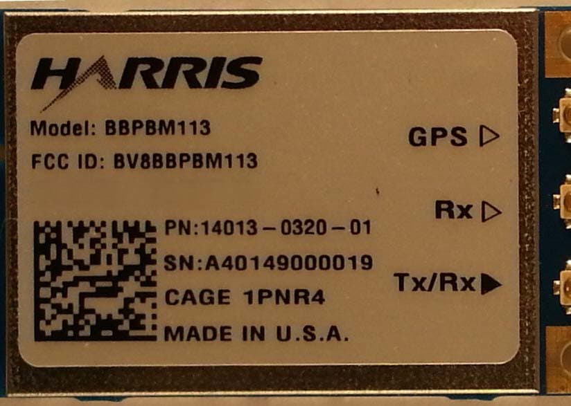
BV8BBPBM113
Apr 11, 2013Wireless Licensed Module
Equipment Class
TNB - Licensed Non-Broadcast Station Transmitter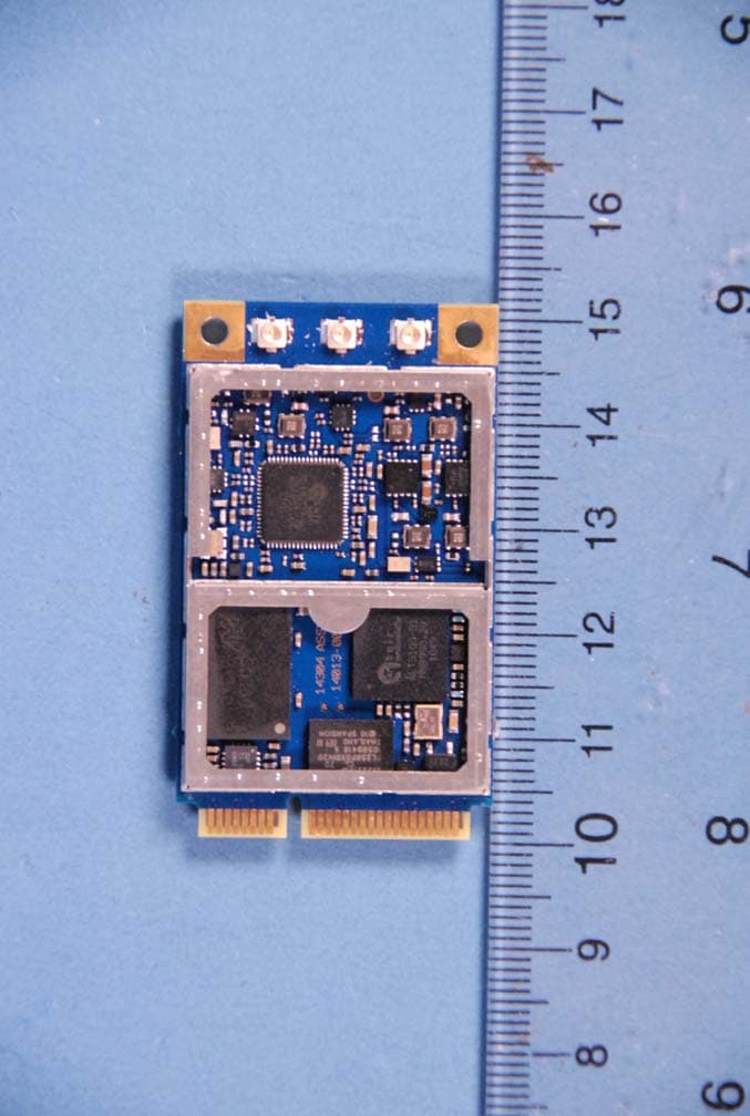
BV8BBPBM100
Feb 09, 2012700 MHz LTE Wireless Module
Equipment Class
TNB - Licensed Non-Broadcast Station Transmitter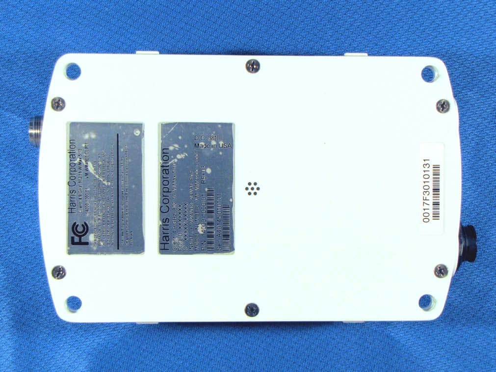
BV8WM4900CL
Nov 21, 2010Client 4.9 GHz 802.16 VBB 5/10
Equipment Class
TNB - Licensed Non-Broadcast Station Transmitter
BV8VIDA-BB-CL
Apr 11, 2007VIDA Broadband High Power Client
Equipment Class
TNB - Licensed Non-Broadcast Station Transmitter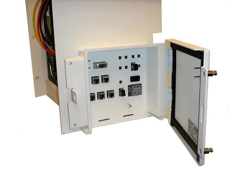
BV8CS900
Apr 08, 2007OpenSky 900 MHz Cell Site
Equipment Class
TNB - Licensed Non-Broadcast Station Transmitter