BVCAMS90604Anti-pilferage Device
Tyco Safety Products/Sensormatic
Click to zoom
Application Details
- Equipment Class
- FAP - Part 15 Anti-Pilferage Device
- Date of Grant
- May 20, 2014
- Application Purpose
- Original Equipment
- Date of Application
- May 20, 2014
- Equipment Note
- Anti-pilferage Device
- Frequency Range
- 0.05600000 - 0.05800000
- Country
- United States
Documents & Files
Document Text
Text extracted from the exhibit documents filed with the FCC. Open a document above to read the original.
Users Manual
Preliminary AMS-9060 CONTROLLER 8200-1014-01, REV. 1A INSTALLATION GUIDE 1 of 13 AMS-9060 Controller Installation Guide ZE9060 ZE9060-2C TYPE: AMS-9060 Contents AMS-9060 Controller ............................................. 1 About this Guide .................................................... 1 To the Installer ....................................................... 1 About the Product .................................................. 2 Installation Requirements ...................................... 3 Controller Installation ............................................. 4 Specifications ...................................................... 12 Declarations ........................................................ 12 About this Guide This installation and setup guide explains how to install the AMS-9060 controller. At least one but no more than four of the hybrid series-parallel versions of the following antennas can be connected to this controller: Ultra•Exit (AMS-1090 Series / AMS-1100 Series) Pro-Max 5 Options that connect to this controller are: AMS-1060 digital remote alarm Passive relays Noise canceling antennas Wired synchronization CBC-4020-216 (UltraLink) or CBC-4055 (LDM II). © 2014 Sensormatic Electronics, LLC. Other documents that may be required for installation are: AMS-9060 Planning Guide, 8200-1014-02 Pro-Max 5 Pedestals Installation Guide, 8200-1014- 07 Ultra•Exit Transceiver Antennas Installation Guide (AMS-1090/AMS-1100 Series), 8200-0537-16 AMC-1060 Digital Remote Alarm Installation Guide, 8200-0505-01 CBC-4055 Local Device Manager II Installation Guide, 8200-0858-01 Wired Sync Hookup Installation Guide, 8200-0537- 07. To the Installer Regulatory Restriction: In certain countries, there may be installation restrictions on the antennas. See antenna installation guides for restrictions, if any. Regulatory Restriction: Except for power input connector all connections are class 2. Regulatory Restriction: For indoor use only. Intended Use: Only install this device as described in this guide. Declaration of Conformity: If this product was installed in a European Union or European Free Trade Association member state, give the Declaration of Conformity included with this product to the manager or user. By law, this information must be provided to the user. Because customer requirements dictate the placement of system components, your Sensormatic representative will supply this information separately. Because of the number of antennas and accessories that can connect to this controller, methodically install this system to avoid problems. See “Connecting Pedestals” in this guide for guidance on how to setup antennas. Do Not Discard! This document may be needed by code inspectors. Leave it at the site until the installation is complete and the system has been approved. Preliminary AMS-9060 CONTROLLER 8200-1014-01, REV. 1A INSTALLATION GUIDE 2 of 13 About the Product The AMS-9060 controller is part of an EAS system that: Includes Ultra•Exit or Pro-Max 5 antennas used to detect tags/labels at exits or in food store checkout aisles. Deters theft by activating an alarm when an antenna detects the unique response of an active Ultra•Max ® hard plastic tag or disposable label. The AMS-9060 controller provides the following installation features: Antenna Support The AMS-9060 controller supports up to two (ZS9060-2) or four (ZS9060) transceiver exit pedestals, or the same number of aisle pedestals, each with separate transmit and receive coils. Antennas can be set up as four transceivers, or four transmit/receive pairs, or combinations of both using a laptop computer and ADS 4 service configurator software. Two receivers can be noise canceling antenna coils. Automatic configuration is available for the commonly used system configurations. Antenna coils can be set for phase flipping (default), aiding, or figure-8 operation. Note: Phase flipping is unavailable when noise canceling antenna coils are used. Alarm Support The controller supports the following alarm devices: – Built-in alarm in the antenna (if used) – Two externally-powered remote alarms such as AMS-1060 digital remote alarms – Up to two relays for devices such as security cameras – Externally-powered Sensormatic alarm management or traffic flow device. Auto Synchronization Auto synchronization occurs during power up or system reset. Auto sync can have different outcomes depending on whether or not nearby EAS transmitters are detected, they are properly aligned to the ac-derived timing of the controller, or too much ambient noise exists. No transmitters detected. During initialization, the controller determines if EAS transmitters are nearby. If none are found, transmitter delay is set to zero at initial power on, or set to the value stored in the controller if not the initial power on. Transmitters detected: Transmitters detected and aligned. If transmitters are correctly aligned, transmitter delay is calculated and stored in the controller for reference. Transmitters detected and not aligned. If transmitters are not aligned, transmitter delay is set to zero at initial power on of the controller, or set according to the value stored the controller if not the initial power on. Too much ambient noise. During initialization, the controller locates other nearby EAS transmitters. If ambient noise prevents the controller from locating nearby EAS controllers and at initial power on of the controller, transmitter delay is set to zero. If not initial power on of the controller, the zero crossing delay stored in the controller is used. Note: The controller stores the zero crossing delay for when the controller could not determine a reliable lock during subsequent power cycles. Instead of using zero for the delay, the controller uses the stored zero crossing delay. Wired Synchronization If a wired Tx sync device is connected to the controller, the controller automatically uses its signal as …
Text truncated - open the document above for the full version.
Cover Letter(s)
May 20, 2014 Timco Engineering, Inc. 849 N.W. State Road 45 P.O. Box 370 Newberry, Florida 32669 USA Re: Application for a Confidential Request for Anti-Pilferage Device, FCC ID: BVCAMS90604 Dear Sir or Madam: Federal Communications Commission Authorization and Evaluation Division Confidentiality Request regarding application for certification. Pursuant to Sections 0.457 and 0.459 of the Commission’s Rules, we hereby request confidential treatment of information accompanying this application as outlined below: AMS-90604 ConfOpDes.pdf AMS-90604 ConfSchemPri.pdf AMS-90604 ConfSchemSec.pdf AMS-90604 ConfBlkDia.pdf The above materials contain trade secrets and proprietary information not customarily released to the public. The public disclosure of these materials may be harmful to the applicant and provide unjustified benefits to its competitors. The applicant understands that pursuant to Section 0.457 of the Rules, disclosure of this application and all accompanying documentation will not be made before the date of the Grant for this application. Sincerely, William D. Owsley Principal EMC Engineer Compliance Engineering Tyco Retail Solutions Sensormatic Electronics, LLC. 6600 Congress Ave. Boca Raton, FL. 33487
Cover Letter(s)
May 20, 2014 Timco Engineering, Inc. 849 N.W. State Road 45 P.O. Box 370 Newberry, Florida 32669 USA Re: Application for a Limited Single Modular Request for Anti-Pilferage Device, FCC ID: BVCAMS90604 Dear Sir or Madam: Federal Communications Commission Authorization and Evaluation Division Pursuant to Section 15.212 (b) of the Commission’s Rules; “(b) A limited modular approval may be granted for single or split modular transmitters that do not comply with all of the above requirements, e.g. , shielding, minimum signaling amplitude, buffered modulation/data inputs, or power supply regulation, if the manufacturer can demonstrate by alternative means in the application for equipment authorization that the modular transmitter meets all the applicable part 15 requirements under the operating conditions in which the transmitter will be used. Limited modular approval also may be granted in those instances where compliance with RF exposure rules is demonstrated only for particular product configurations. The applicant for certification must state how control of the end product into which the module will be installed will be maintained such that full compliance of the end product is always ensured.” Modular approval requirement Yes No * (a) The radio elements must have the radio frequency circuitry must be shielded. Physical/discrete and tuning capacitors may be located external to the shield, but must be on the module assembly. No shielding present. (b) The module shall have buffered modulation/data input(s) (if such inputs are provided) to ensure that the module will comply with the requirements set out in the applicable RSS standard under conditions of excessive data rates or over-modulation. No data is transmitted, thus there are no inputs or buffers. (c) The module shall have its own power supply regulation on the module. This is to ensure that the module will comply with the requirements set out in the applicable standard regardless of the design of the power supplying circuitry in the host device which houses the module. The transmitter power regulation is controlled by the AC Mains. (d) The module shall comply with the provisions for external power amplifiers and antennas detailed in this standard. The equipment certification submission shall contain a detailed description of the configuration of all antennas that will be used with the module. The transmitter drives a resonant loop antenna system. No other power amps or antenna would function with this design. (e) The module shall be tested for compliance with the applicable standard in a stand-alone configuration, i.e. the module must not be inside another device during testing. The design of this transmitter is as a stand-alone system. (f) The module must be labelled with its permanently affixed FCC ID label, or use an electronic display (See KDB Publication 784748 about labelling requirements); The chassis carries the label. (g) The module must comply with all specific rules applicable to the transmitter including all the conditions provided in the integration instructions by the grantee; This transmitter is professionally installed by trained service techs. (h) The module must comply with RF exposure requirements The transmitter operates at frequencies below the limits. This circuit board generates a series of 58 kHz pulses used to activate anti-pilferage tags and detect the resonance of those tags. The transmitter drives a set of loop antennas to establish a magnetic field that interacts with any tags present. These is the first model of this present implementation. There are plans to add more loop antenna configurations and chassis to hold them. Using one transmitter board that can be used for each configuration would be an advantage in time to market. The transmitter does not comply with all the modular requirements. It is not shielded; the transmitter power is not regulated on board, it uses the regulation of the AC Mains; it has no buffered modulation or data inputs being a tuned resonant system that uses one frequency; it is not available to be installed into any other systems or units outside of the applicants control. Testing and results as indicated in the test report, shows that the transmitter meets the general radiated limits of 15.209 from 56 kHz to 1 GHz and also the conducted limits of 15.207. Therefore, as we the applicant will always maintain control of the end product by manufacturing the transmitter board into a variety of chassis with loop antennas, all to perform the same tuned resonant function of detecting anti-pilferage tags, we are applying for a Limited Modular approval. Sincerely, William D. Owsley Principal EMC Engineer Sensormatic Electronics, LLC. 6600 Congress Ave. Boca Raton, FL. 33487
External Photos
FCC ID: BVCAMS90604 IC: 3506A-AMS90604 EUT Photos. 4 channel version FCC ID: BVCAMS90604 IC: 3506A-AMS90604 FCC ID: BVCAMS90604 IC: 3506A-AMS90604 4 channel version
ID Label/Location Info
FCC ID: BVCAMS90602 IC: 3506A-AMS90602 FCC ID: BVCAMS90604 IC: 3506A-AMS90604 FCC Label location.
ID Label/Location Info
FCC ID: BVCAMS90604 IC: 3506A-AMS90604
Internal Photos
FCC ID: BVCAMS90604 IC: 3506A-AMS90604 EUT Photos. 4 channel version FCC ID: BVCAMS90604 IC: 3506A-AMS90604 FCC ID: BVCAMS90604 IC: 3506A-AMS90604 4 channel version
Test Report
FCC ID: BVCAMS90604 IC: 3506A-AMS90604 Page 1 of 24 TYCO / SENSORMATIC, LLC EMC TEST REPORT Model: AMS-9060 FCC ID: BVCAMS90604 IC: 3506A-AMS90604 Intentional Radiator FCC and IC 47 CFR, Part 15, Subpart B, and Subpart C Industry Canada ICES-003e, RSS GENi3, RSS-210i8 Date: April 1, 2014 EMC Engineer 6600 Congress Ave. Boca Raton, FL.USA. 33487 Revision A April 1, 2014 Initial FCC ID: BVCAMS90604 IC: 3506A-AMS90604 Page 2 of 24 1 SUMMARY OF RESULTS ..................................................................................................................... 3 1.1 47 CFR Part 15, Subpart B / Subpart C ............................................................................................. 3 1.2 IC RSS 210 (RSS GEN) ................................................................................................................... 4 2 GENERAL ............................................................................................................................................... 5 2.1 Test Site Registration ........................................................................................................................ 5 2.2 FCC Test Procedures ......................................................................................................................... 5 2.3 Sample Calculation – Radiated & Conducted Emissions ................................................................. 5 2.4 Uncertainty of Measurements ........................................................................................................... 7 3 DESCRIPTION AND CHARACTERISTICS OF THE EUT ................................................................. 8 3.1 Construction Of Equipment Under Test (EUT) ................................................................................ 8 3.2 Overview ........................................................................................................................................... 8 3.3 A limited modular approval .............................................................................................................. 8 3.4 Installation ......................................................................................................................................... 8 3.4.1 Equipment Ratings ..................................................................................................................... 9 3.4.2 Frequency Characteristics And Internal Clocks ......................................................................... 9 4 TEST SET-UP BLOCK DIAGRAM ..................................................................................................... 10 5 FCC TESTS ............................................................................................................................................ 11 5.1.1 Conducted Emissions, FCC Part 15, Clause 15.107 And 15.207 ............................................ 11 5.1.2 Radiated Emissions, FCC Part 15, Clause 15.109 and 15.209 (above 30 MHz) .................... 13 5.1.3 Radiated Emissions, FCC Part 15, Clause 15.209 (below 30 MHz) ....................................... 15 5.1.4 Occupied Bandwidth For Industry Canada – IC. ..................................................................... 20 6 EQUIPMENT LIST ............................................................................................................................... 24 7 End of test report. ................................................................................................................................... 24 FCC ID: BVCAMS90604 IC: 3506A-AMS90604 Page 3 of 24 1 SUMMARY OF RESULTS 1.1 47 CFR Part 15, Subpart B / Subpart C Part PARAMETER TO BE MEASURED Applies Comments SubPart B, Unintentional Radiators (Class B) 15.107 Conducted Disturbance (Conducted Emissions, 0.15-30 MHz) X Complies 15.109 Radiated Disturbance (Radiated Emissions, 30-x000 MHz) X Complies SubPart C, Intentional Radiators (General Limit) 15.207 Conducted Disturbance (Conducted Emissions, 0.15-30 MHz) X Complies 15.209 Radiated Disturbance (Radiated Emissions, 0.009 plus x MHz) X Complies SUMMARY OF RESULTS FCC 47 CFR Part 15. Test Requirement Test Limit Comments 15.15 (b) User Accessible Controls Cannot change output power above limit. The product contains no user accessible controls. Complies. 15.31 (e) Vary Input AC Mains Power Does not increase the output power above the limit. Complies. 15.33 Frequency range of radiated measurements General Limits of 15.209, 9 kHz to 2 GHz. E-field and H-field measurements comply. 15.107 AC Conducted Emissions Unintentional digital emissions subject to Class B limits of 15.107 Digital emissions determined by turning transmitter off. Complies. 15.109 Radiated Emissions Unintentional digital emissions subject to Class B limits of 15.109 Digital emissions determined by turning transmitter off. Complies. 15.203 Antenna Connector Permanently attached or unique coupling or professionally installed. Professionally installed and setup. Complies. 15.204(b)(c) System and Antennas Marketed as a system with authorized antenna types Transmitter capable of driving only loop antennas. Complies. 15.207 (a) (b) AC Conducted Emissions General Limits. Conducted emissions on AC side of DC supply. Complies. 15.205 (a) (b) 15.209 (a) (c) Radiated Emission Comply with limits in 15.209 (a). No intentional emissions in the restricted bands of 15.205 The radiated emissions comply with the general emission limits. FCC ID: BVCAMS90604 IC: 3506A-AMS90604 Page 4 of 24 1.2 IC RSS 210 (RSS GEN) 58 kHz Clause PARAMETER TO BE MEASURED Applies comment 4.6.1 Occupied Bandwidth 99% (-20 dBc) X 7360 Hz 4.6.2 -6 dB Bandwidth X 1175 Hz 4.6.3 -20 dB Bandwidth X 2720 Hz 58 kHz plus 56 kHz Clause PARAMETER TO BE MEASURED Applies comment 4.6.1 Occupied Bandwidth 99% (-20 dBc) X 16700 Hz 4.6.2 -6 dB Bandwidth X 1160 Hz 4.6.3 -20 dB Bandwidth X 3900 Hz FCC ID: BVCAMS90604 IC: 3506A-AMS90604 Page 5 of 24 2 GENERAL…
Text truncated - open the document above for the full version.
Test Setup Photos
FCC ID: BVCAMS90604 IC: 3506A-AMS90604 1 PHOTOS OF TEST SETUPS 1.1 Conducted Emissions AC Mains with all peripherals. FCC ID: BVCAMS90604 IC: 3506A-AMS90604 Cable side FCC ID: BVCAMS90604 IC: 3506A-AMS90604 Antenna cable routing. Cables are typically routed in conduit to antennas. FCC ID: BVCAMS90604 IC: 3506A-AMS90604 1.2 E-field testing on OATS FCC ID: BVCAMS90604 IC: 3506A-AMS90604 1.3 H-field testing at OATS FCC ID: BVCAMS90604 IC: 3506A-AMS90604 1.4 Occupied Bandwidth
Contact Information
Applicant
Mark D. Alexis(Manager Regulatory Compliance)
Test Firm
SensormaticWilliam Owsley
[email protected]5619126462
Technical Specifications
| # | Rule Parts | Frequency Range | Power Output |
|---|---|---|---|
| 1 | 15C | 0.056 MHz - 0.058 MHz | - |
Other Applications from Tyco Safety Products/Sensormatic

BVCIDX5000
Jun 23, 2026UHF RFID Reader
Equipment Class
DSS - Part 15 Spread Spectrum TransmitterBVCAMS1137H
Dec 22, 2025Anti Theft System - Electronic Asset Security
Equipment Class
FAP - Part 15 Anti-Pilferage DeviceBVCAMB9012
Sep 10, 2024Label Deactivator Controller
Equipment Class
DCD - Part 15 Low Power Transmitter Below 1705 kHz
BVC-4000-PI26
Sep 24, 2015RM2L-4000-P126, RM2-4000-P126
Equipment Class
DXX - Part 15 Low Power Communication Device Transmitter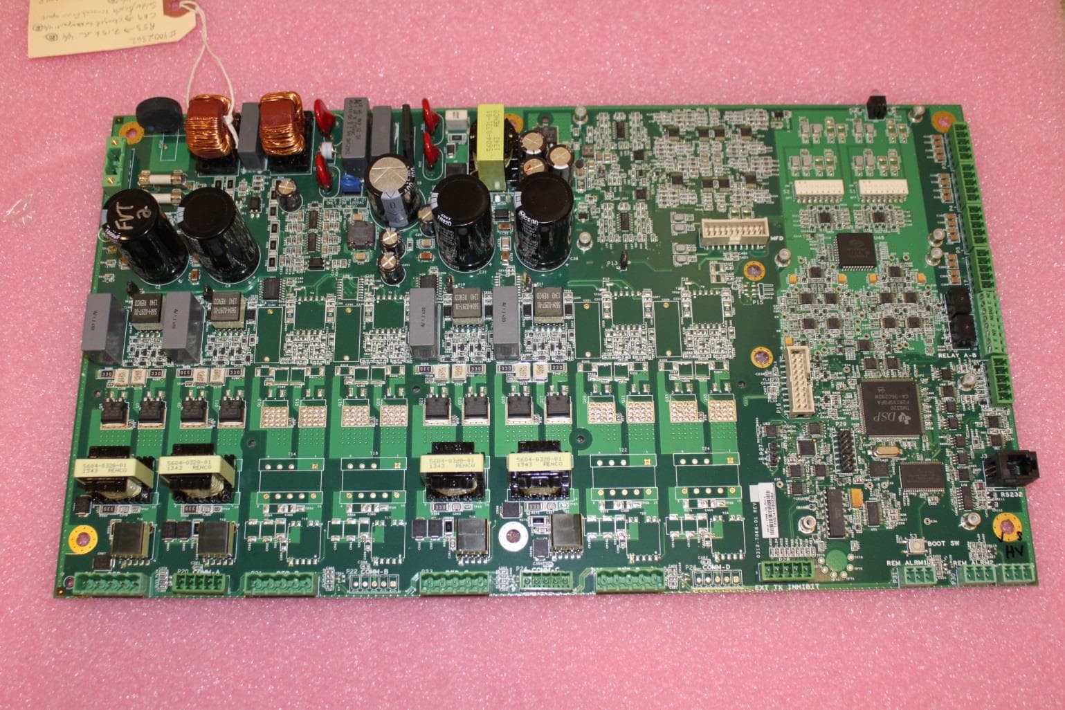
BVCAMS90602
May 20, 2014ANTI-PILFERAGE DEVICE
Equipment Class
FAP - Part 15 Anti-Pilferage Device