BYM1403Wireless belt worn transceiver
HM Electronics Inc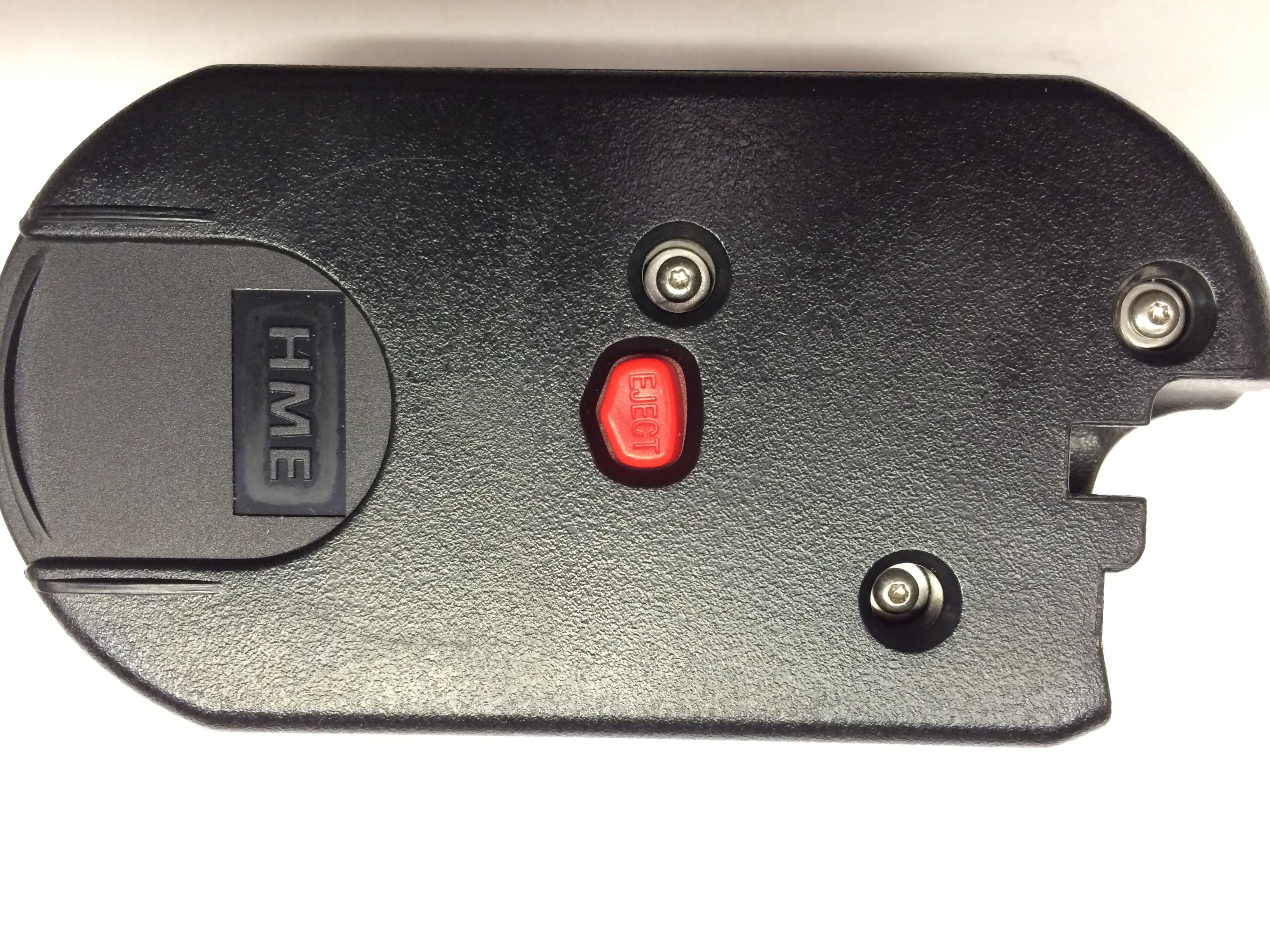
Click to zoom
Application Details
- Equipment Class
- DSS - Part 15 Spread Spectrum Transmitter
- Date of Grant
- Mar 09, 2015
- Application Purpose
- Original Equipment
- Date of Application
- Feb 04, 2015
- Equipment Note
- Wireless belt worn transceiver
- Frequency Range
- 2401.92000000 - 2481.40800000
- Company
- HM Electronics Inc
- Country
- United States
Documents & Files
Document Text
Text extracted from the exhibit documents filed with the FCC. Open a document above to read the original.
Users Manual
Système audio sans fil pour drive-thru Consignes d’installation HME# 400G698F REV A 10/23/14 HM Electronics, Inc. 14110 Stowe Drive Poway, CA 92064 ÉTATS-UNIS Tél. : 1-800-848-4468 Fax: 858-552-0172 HM Electronics, Inc. 14110 Stowe Drive Poway, CA 92064 ÉTATS-UNIS Tél. : 800-848-4468 Fax : 858-552-0172 Site Web: www.hme.com Email: [email protected] Table des matières 1. DESCRIPTION DE L’ÉQUIPEMENT ........................................................................................................................ 1 1.1 Caractéristiques du poste de base ...................................................................................................................................... 2 1.1.1 Panneau avant ................................................................................................................................................................... 2 1.1.2 Panneaux arrière et latéral ................................................................................................................................................. 3 1.2 Caractéristiques du casque ................................................................................................................................................ 4 1.2.1 Contrôles et indicateurs ..................................................................................................................................................... 4 1.2.2 Port correct du casque ....................................................................................................................................................... 5 1.2.3 Retrait et remplacement de la batterie ............................................................................................................................... 5 1.3 Chargeur de batterie .......................................................................................................................................................... 6 1.3.1 Power Adapter Chargeur de batterie pour une utilisation aux États-Unis ......................................................................... 6 1.3.2 Power Adapter Chargeur de batterie pour une utilisation hors des États-Unis .................................................................. 6 1.3.3 Charge de la batterie ......................................................................................................................................................... 7 2. PRÉPARATIFS À L’INSTALLATION ........................................................................................................................ 8 2.1 Outils requis ...................................................................................................................................................................... 8 2 .2 Prévention contre les interférences .................................................................................................................................... 8 2.2.1 Interférence électrique ....................................................................................................................................................... 8 2.2.2 Interférence de fréquence radio (RF) ................................................................................................................................ 9 3. INSTALLATION DE L’ÉQUIPEMENT .................................................................................................................... 10 3.1 Installation du poste de base............................................................................................................................................ 10 3.1.1 Installer les antennes sur le poste de base ....................................................................................................................... 12 3.1.2 Raccorder l'alimentation de la station de base ................................................................................................................. 12 3.1.3 Enregistrer les casque sur le poste de base ...................................................................................................................... 13 3.1.4 Recherche de la meilleure transmission / réception en déplacement ............................................................................... 15 3.1.5 Fixer le poste de base au mur ................................................................ .......................................................................... 15 3.1.6 Installer un kit d'antenne à distance (si nécessaire) ........................................................................................................ 15 3.2 Tirage de câbles .............................................................................................................................................................. 17 3.3 Installation du microphone et des enceintes extérieures et raccords de câbles ................................................................ 17 3.3.1 Installation du Microphone DM5 .................................................................................................................................... 18 3.3.2 Installation du haut-parleur SP10 .................................................................................................................................... 19 3.4 Installation d’un détecteur de véhicules externe optionnel .............................................................................................. 21 3.5 Installation de la carte HME du détecteur de véhicules (Vehicle Detector Board ou VDB) optionnelle ........................ 21 4. PARAMÈTRES DU POSTE DE BASE ...................................................................................................................... 22 4.1 État des Paramètres ......................................................................................................................................................... 22 4.2 Configuratio…
Text truncated - open the document above for the full version.
Users Manual
Wireless Drive-Thru Audio system Installation Instructions HM Electronics, Inc. 14110 Stowe Drive Poway, CA 92064 USA Phone: 800-848-4468 Fax: 858-552-0172 Website: www.hme.com Email: [email protected] HME# 400G698 Rev A1 12/3/14 Table of Contents 1. EQUIPMENT DESCRIPTION...................................................................................................................................... 1 1.1 Base Station Features ........................................................................................................................................................ 2 1.1.1 Front Panel ........................................................................................................................................................................ 2 1.1.2 Rear and Side Panels ......................................................................................................................................................... 3 1.2 Headset Features ............................................................................................................................................................... 4 1.2.1 Controls and Indicators ..................................................................................................................................................... 4 1.2.2 Correct Wearing of Headsets ............................................................................................................................................ 5 1.2.3 Battery Removal and Replacement ................................................................................................................................... 5 1.3 Battery Charger ................................................................................................................................................................. 6 1.3.1 Battery Charger Power Adapter for Use in the United States ........................................................................................... 6 1.3.2 Battery Charger Power Adapter for Use Outside the United States .................................................................................. 6 1 .3.3 Battery Charging ............................................................................................................................................................... 7 2. PREPARATION FOR INSTALLATION ..................................................................................................................... 8 2.1 Tools Required .................................................................................................................................................................. 8 2.2 Interference Prevention ..................................................................................................................................................... 8 2.2.1 Electrical Interference ....................................................................................................................................................... 8 2.2.2 Radio Frequency (RF) Interference ................................................................................................................................... 9 3. EQUIPMENT INSTALLATION ................................................................................................................................. 10 3.1 Base Station Installation .................................................................................................................................................. 10 3.1.1 Install Antennas on Base Station ..................................................................................................................................... 12 3.1.2 Connect Base Station Power Supply ............................................................................................................................... 12 3.1.3 Register Headsets to Base Station ................................................................................................................................... 13 3.1.4 Walk Test for Best Transmission/Reception ................................................................................................................... 15 3.1.5 Mount Base Station on Wall ........................................................................................................................................... 15 3.1.6 Install Remote Antenna Kit (if needed)........................................................................................................................... 15 3.2 Cable Pulling ................................................................................................................................................................... 17 3 .3 Outside Microphone and Speaker Installation and Cable Connections ........................................................................... 17 3.3.1 Install DM5 Microphone ................................................................................................................................................. 18 3.3.2 Install SP10 Speaker ....................................................................................................................................................... 19 3.4 Optional External Vehicle Detector Installation ............................................................................................................. 21 3.5 Optional HME Vehicle Detector Board (VDB) Installation ........................................................................................... 21 4. BASE STATION SETTINGS ...................................................................................................................................... 22 4.1 Settings Status ................................................................................................................................................................. 22 4.2 Basic Installer Setups ....…
Text truncated - open the document above for the full version.
Internal Photos
For the best experience, open this PDF portfolio in Acrobat 9 or Adobe Reader 9, or later. Get Adobe Reader Now!
RF Exposure Info
SAR Exclusion Justification Test exclusion thresholds for 100 MHz to 6 GHz at test separation distances ≤ 50 mm Guidance document reference: 447498 D01 General RF Exposure Guidance v05r01, page 11, paragraph 4.3.1(1). The 1-g and 10-g SAR test exclusion thresholds for 100 MHz to 6 GHz at test separation distances ≤ 50 mm are determined by: [(max. power of channel, including tune-up tolerance, mW)/(min. test separation distance, mm)] * [√f(GHz)] ≤ 3.0 for 1-g SAR and ≤ 7.5 for 10-g extremity SAR, where • f(GHz) is the RF channel transmit frequency in GHz • Power and distance are rounded to the nearest mW and mm before calculation • The result is rounded to one decimal place for comparison • 3.0 and 7.5 are referred to as the numeric thresholds in the step 2 below The test exclusions are applicable only when the minimum test separation distance is ≤ 50 mm and for transmission frequencies between 100 MHz and 6 GHz. When the minimum test separation distance is < 5 mm, a distance of 5 mm according to 5) in section 4.1 is applied to determine SAR test exclusion. SAR test exclusion analysis: Assumptions: Since the exact separation distance may vary, the minimum separation distance of 5 mm is assumed per the guidance document. Scaling of rf power output: Maximum peak rf output power from page 15 of test report 2014_272452_FCC_15247 is 87.1 mW The system uses a source –based duty cycle. The system is TDMA based using 2 of 20 evenly spaced time slots (see page 12 of test report). This makes the source-based duty cycle a ratio of 1:10. The power is therefore scaled by a factor of 10 for the purpose of this analysis making the peak power of 87 mW a value of 8.7 mW average. Measured peak power: 87 mW Source-based average power = 87 mW/10 = 8.7 mW Max. power of channel: 8.7 mW Min. separation distance:5mm Max. frequency: 2.48GHz [(Pwr/Dist)* √Freq.] = 2.7 The result of the above SAR threshold calculation demonstrates that the result is less than the 1-g numeric threshold of 3 and the 10-g numeric threshold of 7.5. Conclusion: The above analysis shows that the evaluated device qualifies for exemption from SAR testing for both 1-g and 10-g SAR. Signed: David Light 3/2/2015 Nemko USA, Inc.
Test Report
Nemko Test Report: 2014_272452_FCC_15247_Rev2 Applicant: HM Electronics, Inc. 14110 Stowe Drive Poway, CA 92064 USA Equipment Under Test: 1403 (E.U.T.) FCC Identifier: BYM1403 IC Identifier: 1860A-1403 In Accordance With: FCC Part 15, Subpart C, 15.247 and Industry Canada RSS-210, Issue 8 Frequency Hopping Transmitters Tested By: Nemko USA, Inc. 2210 Faraday Ave. Ste 150 Carlsbad, CA 92008 USA TESTED BY: DATE: 21 November 2014 David Light, Wireless Engineer APPROVED BY: DATE: 3 December 2014 Tom Tidwell, Nemko Reviewer Total Number of Pages: 38 Nemko USA, Inc. FCC PART 15, SUBPART C and Industry Canada RSS-210 Issue 8 FREQUENCY HOPPING SPREAD SPECTRUM TRANSMITTER EQUIPMENT: 1403 PROJECT NO.: 2014_272452_FCC_15247_rev2 Page 2 of 38 Table of Contents SECTION 1. SUMMARY OF TEST RESULTS 3 SECTION 2. EQUIPMENT UNDER TEST (E.U.T.) 5 SECTION 3. CHANNEL SEPARATION 6 SECTION 4. TIME OF OCCUPANCY 11 SECTION 5. PEAK POWER OUTPUT 15 SECTION 6. SPURIOUS EMISSIONS (CONDUCTED) 19 SECTION 7. SPURIOUS EMISSIONS (RADIATED) 24 SECTION 8. TEST EQUIPMENT LIST 27 ANNEX A - TEST DETAILS 28 ANNEX B - TEST DIAGRAMS 36 Nemko USA, Inc. FCC PART 15, SUBPART C and Industry Canada RSS-210 Issue 8 FREQUENCY HOPPING SPREAD SPECTRUM TRANSMITTER EQUIPMENT: 1403 PROJECT NO.: 2014_272452_FCC_15247_rev2 Page 3 of 38 Section 1. Summary of Test Results Manufacturer: HM Electronics, Inc. Model No.: 1403 Serial No.: None General: All measurements are traceable to national standards. These tests were conducted on a sample of the equipment for the purpose of demonstrating compliance with Part 15, Subpart C, Paragraph 15.247 and Industry Canada RSS-210, Issue 8 for Frequency Hopping Spread Spectrum devices. Radiated tests were conducted is accordance with ANSI C63.4-2003. Radiated emissions are made on an open area test site. A description of the test facility is on file with the FCC and Industry Canada. New Submission Production Unit Class II Permissive Change Pre-Production Unit THIS TEST REPORT RELATES ONLY TO THE ITEM(S) TESTED. THE FOLLOWING DEVIATIONS FROM, ADDITIONS TO, OR EXCLUSIONS FROM THE TEST SPECIFICATIONS HAVE BEEN MADE. See “ Summary of Test Data”. NVLAP Lab Code 200116-0 This report must not be used to claim product certification, approval, or endorsement by NVLAP, NIST, or any agency of the Federal Government. Nemko USA, Inc. is a NVLAP accredited laboratory. Nemko USA Inc. authorizes the above named company to reproduce this report provided it is reproduced in its entirety and for use by the company’s employees only. Any use which a third party makes of this report, or any reliance on or decisions to be made based on it, are the responsibility of such third parties. Nemko USA Inc. accepts no responsibility for damages, if any, suffered by any third party as a result of decisions made or actions based on this report. This report applies only to the items tested. Nemko USA, Inc. FCC PART 15, SUBPART C and Industry Canada RSS-210 Issue 8 FREQUENCY HOPPING SPREAD SPECTRUM TRANSMITTER EQUIPMENT: 1403 PROJECT NO.: 2014_272452_FCC_15247_rev2 Page 4 of 38 Summary Of Test Data NAME OF TEST PARA. NO. RESULT Powerline Conducted Emissions 15.207(a) / RSS-Gen 7.2.4 NA Channel Separation 15.247(a)(1) / RSS-210 A8.1(b) Complies Time of Occupancy 15.247(a)(1) / RSS-210 A8.1(d) Complies 20 dB Occupied Bandwidth 15.247(a)(1) / RSS-210 A8.1(a) Complies Peak Power Output 15.247(b) / RSS-210 A8.4(2) Complies Spurious Emissions (Conducted) 15.247(d) / RSS-210 A8.5 Complies Spurious Emissions (Radiated) 15.247(d) / RSS-Gen 7.2.2 Complies Footnotes: The EUT is powered by a 3.7 V lithium battery. Nemko USA, Inc. FCC PART 15, SUBPART C and Industry Canada RSS-210 Issue 8 FREQUENCY HOPPING SPREAD SPECTRUM TRANSMITTER EQUIPMENT: 1403 PROJECT NO.: 2014_272452_FCC_15247_rev2 Page 5 of 38 Section 2. Equipment Under Test (E.U.T.) General Equipment Information Frequency Band: 902 – 928 MHz 2400 – 2483.5 MHz 5725 – 5850 MHz Operating Frequency Range: 2401.92 to 2481.408 MHz Number of Channels: 47 Channel Spacing: 1.72 MHz User Frequency Adjustment: Software controlled Software Version Ver. 2.10 Description of EUT The 1403 is a 2.4 GHz FHSS wireless, belt worn transceiver designed to operate with a base station transceiver. Nemko USA, Inc. FCC PART 15, SUBPART C and Industry Canada RSS-210 Issue 8 FREQUENCY HOPPING SPREAD SPECTRUM TRANSMITTER EQUIPMENT: 1403 PROJECT NO.: 2014_272452_FCC_15247_rev2 Page 6 of 38 Section 3. Channel Separation NAME OF TEST: Channel Separation PARA. NO.: 15.247(a)(1) TESTED BY: David Light DATE: 21 Nov. 2014 Test Results: Complies. Measurement Data: See 20 dB BW plot Measured 20 dB bandwidth: 1.28 MHz Channel Separation: 1.72 MHz Equipment Used: 1036 Measurement Uncertainty: 1X10 -7 ppm Temperature: 20 C Relative Humidity: 30 % Nemko USA, Inc. FCC PART 15, SUBPART C and Industry Canada RSS-210 Issue 8 FREQUENCY HOPPING SPREAD SPECTRUM TRANSMITTER EQUIPMENT: 1403 PROJECT NO.: 2014_272452_FCC_15247_rev2 Page 7 of 38 Test Data – Channel Separation Nemko USA, Inc. FCC PART 15, SUBPART C and Industry Canada RSS-210 Issue 8 FREQUENCY HOPPING SPREAD SPECTRUM TRANSMITTER EQUIPMENT: 1403 PROJECT NO.: 2014_272452_FCC_15247_rev2 Page 8 of 38 Test Data – 20 dB Bandwidth Low Channel Nemko USA, Inc. FCC PART 15, SUBPART C and Industry Canada RSS-210 Issue 8 FREQUENCY HOPPING SPREAD SPECTRUM TRANSMITTER EQUIPMENT: 1403 PROJECT NO.: 2014_272452_FCC_15247_rev2 Page 9 of 38 Test Data – 20 dB Bandwidth Mid Channel Nemko USA, Inc. FCC PART 15, SUBPART C and Industry Canada RSS-210 Issue 8 FREQUENCY HOPPING SPREAD SPECTRUM TRANSMITTER EQUIPMENT: 1403 PROJECT NO.: 2014_272452_FCC_15247_rev2 Page 10 of 38 Test Data – 20 dB Bandwidth High Channel Nemko USA, Inc. FCC PART 15, SUBPART C and Industry Canada RSS-210 Issue 8 FREQUENCY HOPPING SPREAD SPECTRUM TRANSMITTER EQUIPMENT: 1403 PROJECT NO.: 2014_272452_FCC_15247_rev2 Page 11 of 38 Section 4. Time of Occupancy NAME OF TEST: Time of Occupancy PARA. NO.: 15.247(a)(1) TESTED BY: David Light D…
Text truncated - open the document above for the full version.
Contact Information
Applicant
Manuel Liong Jr(Staff Regulatory Engineer)
Test Firm
Nemko USA, Inc. - San Diego EMC DivisionJan Blomgren
[email protected]760-444-3500
Technical Specifications
| # | Rule Parts | Frequency Range | Power Output |
|---|---|---|---|
| 1 | 15C | 2.40 GHz - 2.48 GHz | 87.00 mW |
Other Applications from HM Electronics Inc
BYMBP5GC1
Apr 23, 2026Wireless Beltpack
Equipment Class
CBE - Citizens Band End User Devices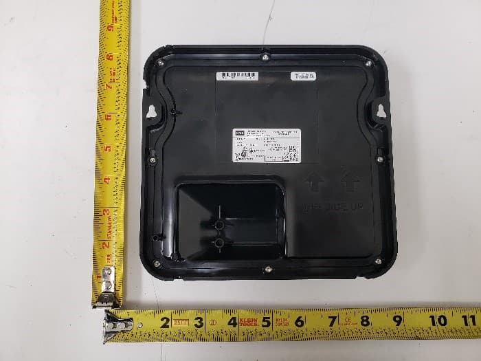
BYM7000A
Aug 12, 2024Remote Transceiver
Equipment Class
NII - Unlicensed National Information Infrastructure TX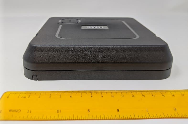
BYM7000
Mar 15, 2021Remote Transceiver
Equipment Class
NII - Unlicensed National Information Infrastructure TX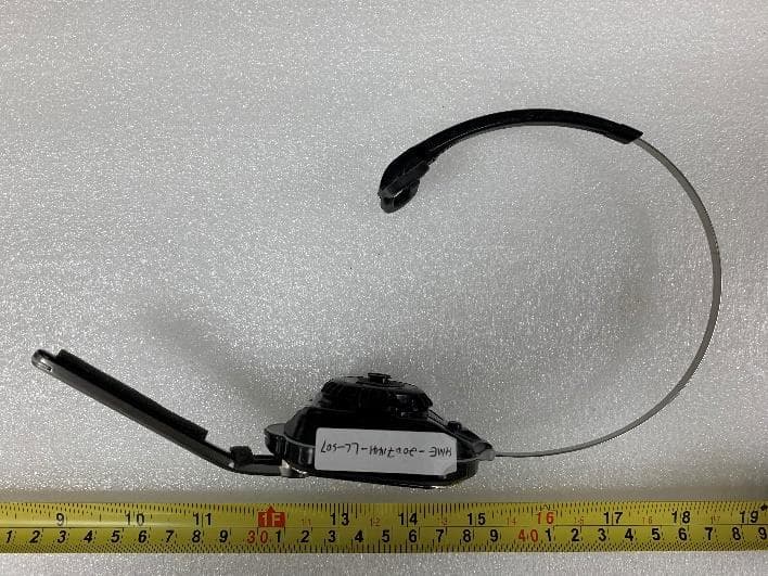
BYM7002
Mar 15, 2021Nexeo AIO headset
Equipment Class
DTS - Digital Transmission System
BYM-AC70
Dec 20, 2020Battery Charger
Equipment Class
DTS - Digital Transmission System