BYM7000ARemote Transceiver
HM Electronics Inc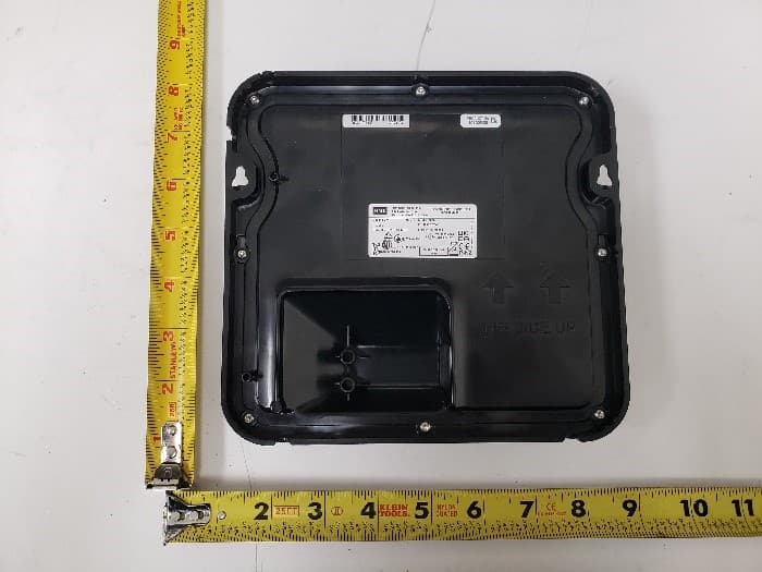
Click to zoom
Application Details
- Equipment Class
- NII - Unlicensed National Information Infrastructure TX
- Date of Grant
- Aug 12, 2024
- Application Purpose
- Original Equipment
- Date of Application
- Aug 12, 2024
- Equipment Note
- Remote Transceiver
- Frequency Range
- 5745.00000000 - 5825.00000000
- Company
- HM Electronics Inc
- Country
- United States
Documents & Files
Document Text
Text extracted from the exhibit documents filed with the FCC. Open a document above to read the original.
Users Manual
Quick Reference Installation Guide HM ELECTRONICS, INC. 2848 Whiptail Loop, Carlsbad, CA 92010 USA Phone: 1-800-848-4468 Fax: 858-552-0172 Website: www.hme.com Email: [email protected] HME# PUB - 000xx Rev A 09/01/20 RT7000 REMOTE TRANSCEIVER The RT7000 Remote Transceiver facilitates Base Station to Headset communication. It uses a wired connection to the Base Station but is wireless for Headset communication. Up to four RT7000s can be connected to the Base Station for additional coverage. TOOLS/EQUIPMENT REQUIRED • Drill and drill bit set • Screwdriver (Phillips #2), tape measure, pencil/maker • Fish stick, cable ties, safety glasses, ladder INSTALLATION, SETUP, AND OPERATION 1. Survey the premises to determine a good location to mount the RT7000 (see Remote Transceiver RT7000 Notes on the next page). 2. Once a good location is selected, route the Ethernet cable from the Base Station to the RT7000 location. 3. Loosely mount the Remote Transceiver in an optimal location (until range tested with a roving headset using the Installation Wizard via the Base Station in step 5. 4. Connect the Ethernet cable to the RJ45 port on the rear of the RT7000 (see Fig. 2) and the other end to one of the available ports on the Base Station (see Fig. 4 and Table 1). 5. At the Base Station LOG IN to the system, go to SYSTEM, then the ADVANCED tab and select “Installation” from the drop- down menu. Tap the “Start Installation Wizard” button. This opens the Installation Wizard as shown in Fig. 3. Fig. 3 6. Follow the Transceiver Installation steps that follow. Once you have used a headset in Reception Location Mode to walk the premises to determine the mounting location is good, move on to the next step. If the mounting location is not a good one, move the Remote Transceiver to another location and repeat steps 1 through 6, until a good location is found. 7. Drill two holes 6.625 inches (16.83 cm) apart along a horizontal axis on the wall (avoid electrical or plumbing obstructions). 8. Install the provided hardware but do not tighten, leave a gap (~ ¹/8 th inch (3.2 mm)) between the screw heads and wall. 9. Align the RT7000 mounting holes with the two screws (Fig. 2). Fig. 1 Fig. 2 Fig. 4 12 34 RT7000 TRANSCEIVER Front View RT7000 TRANSCEIVER Rear View THIS SIDE UP Mounting Holes RJ45 Port for Ethernet cable 12 34 RT7000 TRANSCEIVER Front View RT7000 TRANSCEIVER Rear View THIS SIDE UP Mounting Holes RJ45 Port for Ethernet cable NEXEO BASE STATION PCBA (Partial) Remote XCVR 1 Remote XCVR 2 Remote XCVR 3 Remote XCVR 4 Ethernet/ Network Telephone Interface Timer Greet Veh Detect 1 Timer Greet Veh Detect 2 Veh Detect Inputs Alert Inputs Remote Switches Early Warnings Power In DC + DC - GND Micro USB J200 J600 J201J800J801 J802 J805 J804 J803 J2003 J3000 J4500J4501 J1400 J3200 J3400 J3600 J3800 1 1 1 1 111 1 1 1 1 Serial Debug USB J?301 J?300 J1 PCBA Side View Detail Ethernet (Network) Remote Module 1 Remote Module 2 Remote Module 3 Remote Module 4 Power Transceiver (x4) 12 34 Vertical Mount Only (this way up) REMOTE TRANSCEIVER (RT7000) © 2020 HM Electronics, Inc. All rights reserved. 2 Safety Notice CAUTION: Wear proper eye, ear, and body protection when grinding, drilling or working with tools. Follow the manufactur- er’s safety information and operational instructions for tools and materials. Be aware of your surroundings. Failure to heed such precautions can cause injury and/or property damage. Hygiene, Health, and Safety Part of this installation requires working within a restaurant/store where food is prepared, and customers dine. Please consult the restaurant/store manager, standard operating procedures and any additional restaurant safety/advisory protocols available before be- ginning work within the restaurant/store. Follow the instructions and guidelines provided. 10. Mount the RT7000 over the screw heads until flush against the wall, then slide it down onto the screws to secure it in place and tighten hardware. 11. The other end of the Ethernet cable is connected to the Base Station (see Fig. 4 and the Table 1 for connections). 12. The Base Station provides power to the RT7000. So when connected, the center LED in the circle on the front of the RT7000 turns on solid green. 13. The peripheral LED around the circle initially flash- es as the RT7000 completes a scan of the environ- ment. Once the scan is finished, this peripheral LED also turns solid green. Note: This LED also flashes blue when the firmware is updating. 14. The RT7000 is now operational. The Base Station HOME screen also provides a color-coded visual status (see "Transceivers" status in Fig. 5). Fig. 5 Tap "Transceivers" on the HOME screen for more details (see Fig. 6). Fig. 6 Remote Transceiver (RT7000) Notes: • Mount the transceiver high in a central location to headset usage. • Maximize line of sight between the transceiver and headsets in an area free from obstructions and equipment/materials that can interfere with signal propagation. These include walls, large metal ap- pliances, hoods, and backsplashes, etc. • Mount the transceiver vertically on a wall in the upright position (see arrow on Transceiver rear). Do NOT mount horizontally such as on a ceiling, this will reduce the transceiver’s range. • Signal propagation is strongest directly in front of the Transceiver and then to the sides. • The RT7000 uses an Ethernet (Cat5 or Cat6) cable. Do not exceed 1000’ (304 m). • Large premises may require more than one Trans- ceiver. Up to four Transceivers are supported by one Base Station. • Once connected to the Base Station, the LED in the middle of the circle on the transceiver front illuminates to indicate it is turned on. One of the outer LEDs (numbered 1 to 4) around the circle also turns on (depending on which port the Transceiver is connected to on the Base Station, see Fig. 7). This outer LED will initially flash as the Transceiver scans for available channels before turning solid green once a channel is found (on the Base Statio…
Text truncated - open the document above for the full version.
Attestation Statements
HM Electronics, Inc. | 2848 Whiptail Loop | Carlsbad, CA 92010 800.848.4468 | www.hme.com FCC Attestation Statement US Agent For Service Federal Communications Commission Authorization and Evaluation Division 7435 Oakland Mills Road Columbia, MD 21046 Date: __05/03/2024___ Ref: Attestation Statements Part 2.911(d)(7) Filing FCC Application for FCC ID: ____BYM7000A_______ ____ HM Electronics, Inc.____ certifies that, as of the date of the filing of the application, ____ HM Electronics, Inc.___ is our designated U.S. agent for service of process for the above reference FCC ID: _______BYM7000A____. ____ HM Electronics, Inc.____ agrees to maintain an agent for no less than one year after the grantee has terminated all marketing and importation or the conclusion of any Commission- related proceedings involving the equipment. ___ HM Electronics, Inc.____ accepts, as of the date of the filing of the application, the obligation of the designated U.S. agent for service of process for above referenced FCC ID. Designated U.S. Agent Information: Name: HM Electronics, Inc. Address: 2848 Whiptail Loop, Carlsbad, CA 92010, USA Contact Person: Manuel Liong Jr. Telephone: +1-858-535-6000 Email: [email protected] FRN: 0005870704 Sincerely, Applicant’s name: Manuel Liong Jr. Applicant’s title: Staff Regulatory Engineer Applicant’s Signature: Agent’s name: Manuel Liong Jr. Agent’s title: Staff Regulatory Engineer Agent’s Signature:
Attestation Statements
HM Electronics, Inc. | 2848 Whiptail Loop | Carlsbad, CA 92010 800.848.4468 | www.hme.com Attestation Statement Letter I Federal Communications Commission Authorization and Evaluation Division 7435 Oakland Mills Road Columbia, MD 21046 Date: __05/03/2024___ Ref: Attestation Statements Part 2.911(d)(5)(i) Filing FCC Application for FCC ID: ____BYM7000A_______ ___ HM Electronics, Inc.__ certifies that the equipment for which authorization is sought is not “covered” equipment prohibited for receiving an equipment authorization pursuant to section 2.903 of the FCC rules. Sincerely, Client’s signature: Client’s name: Manuel Liong Jr. Client’s title: Staff Regulatory Engineer Company Name: HM Electronics, Inc. Company Address: 2848 Whiptail Loop, Carlsbad, CA 92010, USA Main: +1-858-535-6000
Attestation Statements
HM Electronics, Inc. | 2848 Whiptail Loop | Carlsbad, CA 92010 800.848.4468 | www.hme.com Attestation Statement Letter II Federal Communications Commission Authorization and Evaluation Division 7435 Oakland Mills Road Columbia, MD 21046 USA Date: __05/03/2024___ Ref: Attestation Statements Part 2.911(d)(5)(ii) Filing FCC Application for FCC ID: ____BYM7000A_______ ___ HM Electronics, Inc.__ certifies that, as of the date of the filing of the application, the applicant is not identified on the Covered List as an entity producing “covered” equipment. Sincerely, Client’s signature: Client’s name: Manuel Liong Jr. Client’s title: Staff Regulatory Engineer Company Name: HM Electronics, Inc. Company Address: 2848 Whiptail Loop, Carlsbad, CA 92010, USA Main: +1-858-535-6000
Cover Letter(s)
HM Electronics, Inc. | 2848 Whiptail Loop | Carlsbad, CA 92010 800.848.4468 | www.hme.com Federal Communications Commission Authorization and Evaluation Division 7435 Oakland Mills Road Columbia, MD 21046 Date: 05/03/2024 SUBJECT: FCC Application for (FCC ID: BYM7000A) To Whom It May Concern: We, the undersigned, hereby authorize __David Zhang_____ in _____Vista Laboratories, Inc.___ on our behalf, to apply to the Federal Communications Commission on our equipment. All lawful acts carried out by ____ Vista Laboratories, Inc.____ on our behalf shall have the same effect as acts of our own. This is to advise that we are in full compliance with the Anti- Drug Abuse Act. We, the applicant, are not subject to a denial of federal benefits pursuant to Section 5301 of the Anti-Drug Act of 1988, 21 USC853a, and no party to the application is subject to a denial of federal benefits pursuant to that section. Sincerely, Client’s signature: Client’s name: Manuel Liong Jr. Client’s title: Staff Regulatory Engineer Company Name: HM Electronics, Inc. Company Address: 2848 Whiptail Loop, Carlsbad, CA 92010, USA Main: +1-858-535-6000
Cover Letter(s)
HM Electronics, Inc. | 2848 Whiptail Loop | Carlsbad, CA 92010 800.848.4468 | www.hme.com Federal Communications Commission Authorization and Evaluation Division Confidentiality Request regarding application for certification of FCC ID: BYM7000A Pursuant to Sections 0.457 and 0.459 of the Commission’s Rules, we hereby request confidential treatment of information accompanying this application as outlined below: Type of Confidentiality Requested Exhibit Type ☐Short Term ☒Permanent Block Diagrams ☐Short Term External Photos ☒Short Term ☐Permanent* Internal Photos ☐Short Term ☒Permanent Operation Description ☐Short Term ☒Permanent Parts List/BOM ☐Short Term ☒Permanent Schematics ☐Short Term Test Setup Photos ☐Short Term ☐Permanent* User manual *Requires further justification before permanent confidentiality will be allowed. The above materials contain trade secrets and proprietary information not customarily released to the public. The public disclosure of these materials may be harmful to the applicant and provide unjustified benefits to its competitors. Permanent Confidentiality: The applicant requests the exhibits listed above as permanently confidential be withheld from public review due to materials that contain trade secrets and proprietary information not customarily released to the public. Short-Term Confidentiality: Pursuant to DA04-1705 June 15, 2004 of the Commission’s public notice, we also request temporary confidential treatment of information accompanying this application as outlined below for an initial period of 180 (ie - “45”, “90” or “180”) days. Sincerely, Client’s signature: Client’s name: Manuel Liong Jr. Client’s title: Staff Regulatory Engineer Company Name: HM Electronics, Inc. Company Address: 2848 Whiptail Loop, Carlsbad, CA 92010, USA Main: +1-858-535-6000
External Photos
EUT Top View EUT Bottom View EUT Right View EUT Left View EUT Front View EUT Back View
ID Label/Location Info
EUT Bottom View
RF Exposure Info
FCC MPE Evaluation (FCC ID: BYM7000A) RF Exposure Requirements: 47 CFR §1.1307(b) RF Radiation Exposure Limits: 47 CFR §1.1310 RF Radiation Exposure Guidelines: FCC OST/OET Bulletin Number 65 EUT Frequency Band: 5180-5825MHz Limits for General Population/Uncontrolled Exposure in the band of: 300 - 1500 MHz Power Density Limit: f/1500 mW/cm2 Limits for General Population/Uncontrolled Exposure in the band of: 1500 - 100,000 MHz Power Density Limit: 1 mW / cm 2 Equation: S = PG / 4R 2 or R = √PG / 4S Where, S = Power Density P = Power Input to Antenna G = Antenna Gain R = distance to the center of radiated antenna ____________________________________________________________________________________________________________ Prediction distance 20 cm EUT: Base Transceiver Radio Frequency (MHz) Max Conducted Output Power (dBm) Antenna Gain (dBi) Separation distance (cm) Power Density (mW/ cm 2 ) MPE Limit (mW/ cm 2 ) 5GHz 5180-5240 24.69 3 20 0.1169 1 5GHz 5260-5320 22.71 3 20 0.0741 1 5GHz 5500-5720 22.28 3 20 0.0671 1 5GHz 5745-5825 24.04 3 20 0.1006 1 The above results show that the device complies with the MPE requirement. Completed By: Lining Li Vista Laboratories, Inc. 1261 Puerta Del Sol, San Clemente, CA 92673 Date: 05/23/2024
Test Report
Phone: +1 (949) 393-1123 Web: www.vista-compliance.com Email: [email protected] FCC RF Test Report Test Report Number HME-24050131-LC-FCC-UNII FCC ID Applicant BYM7000A HM Electronics Inc Applicant Address 2848 Whiptail Loop, Carlsbad, CA 92010 USA Product Name Remote Transceiver Model (s) 7000 Date of Receipt 06/18/2020 (initial), 05/02/2024 (additional) Date of Test 06/18/2020 – 08/21/2020 (initial) 05/21/2024 – 05/22/2024 (additional) Report Issue Date 05/23/2024 Test Standards 47CFR Part 15.407 Test Result PASS Issued by: Vista Compliance Laboratories 1261 Puerta Del Sol, San Clemente, CA 92673 USA www.vista-compliance.com Lining Li (Test Engineer) David Zhang (Technical Manager) This report is for the exclusive use of the applicant. Any copying or replication of this report to or for any other person or entity, or use of our name or trademark, is permitted only with our prior written permission. Note that the results contained in this report pertain only to the test samples identified herein, and the results relate only to the items tested and the results that were obtained in the period between the date of initial receipt of samples and the date of issue of the report. This report sets forth our findings solely with respect to the test samples identified herein. The results set forth in this report are not indicative or representative of the quality or characteristics of the lot from which a test sample was taken or any similar or identical product unless specifically and expressly noted. Our report includes all of the tests requested and the results thereof based upon the information provided to us. The applicant has 60 days from date of issuance of this report to notify us of any material error or omission. Failure to raise such issue within the prescribed time shall constitute your unqualified acceptance of the completeness of this report, the tests conducted and the correctness of the report contents. Unless specific mention, the uncertainty of measurement has been explicitly taken into account to declare the compliance or non-compliance to the specification. The report must not be used by the client to claim product certification, approval, or endorsement by any government agencies. This report is not to be reproduced by any means except in full and in any case not without the written approval of Vista Laboratories. Report # HME-24050131-LC-FCC-UNII Page 2 of 61 REVISION HISTORY Report Number Version Description Issued Date HME-24050131-LC-FCC-UNII Original Initial report 05/23/2024 Report # HME-24050131-LC-FCC-UNII Page 3 of 61 TABLE OF CONTENTS 1 TEST SUMMARY ...................................................................................................................................................... 4 2 GENERAL INFORMATION ..................................................................................................................................... 5 2.1 Applicant ................................................................................................................................................. 5 2.2 Product information .............................................................................................................................. 5 2.3 Test standard and method ................................................................................................................... 5 3 TEST SITE INFORMATION ..................................................................................................................................... 6 4 MODIFICATION OF EUT / DEVIATIONS FROM STANDARDS ....................................................................... 6 5 TEST CONFIGURATION AND OPERATION ....................................................................................................... 6 5.1 EUT Test Configuration ......................................................................................................................... 6 5.2 Supporting Equipment .......................................................................................................................... 6 6 UNCERTAINTY OF MEASUREMENT ................................................................................................................... 8 7 TEST RESULTS .......................................................................................................................................................... 9 7.1 Antenna Requirement........................................................................................................................... 9 7.2 6 d Bandwidth ...................................................................................................................................... 10 7.3 26 d Bandwidth .................................................................................................................................... 13 7.4 Maximum Output Power .................................................................................................................... 17 7.5 Power Spectral Density ....................................................................................................................... 24 7.6 Automatically Discontinue Transmission ......................................................................................... 28 7.7 Radiated Spurious Emissions into Restricted Frequency Bands ................................................... 29 7.8 Conducted Emissions .......................................................................................................................... 55 8 EUT AND TEST SETUP PHOTOS ......................................................................................................................... 59 9 TEST INSTRUMENT LIST ..................................................................................................................................... 61 Report # HME-24050131-LC-FCC-UNII Page 4 of 61 1 Test Summary Test Item Test Requi…
Text truncated - open the document above for the full version.
Test Report
5GHz Antenna Information Item Detail Antenna type Internal PCB antenna (PIFA antenna) Frequency Range 5180-5825MHz Antenna Dimention (LxW) 19 mm (L) x 14 mm (W) Gain and directivity characteristics of the antenna (if applicable) Antenna peak gain: 3 dBi Antenna directivity: N/A Beam forming Gain N/A Antenna directivity pattern N/A Antenna Polarization N/A Antenna connector type N/A Antenna manufacturer and model Antenna manufacturer: HM Electronics Inc Antenna model: ANT2 Antenna Photo
Test Setup Photos
RE Below 1GHz – Front View RE Below 1GHz – Rear View RE Above 1GHz – Front View RE Above 1GHz – Rear View AC Line CE – Front View AC Line CE – Rear View
Contact Information
Applicant
Manuel Liong Jr(Staff Regulatory Engineer)
Test Firm
Vista Laboratories, Inc.David Zhang
[email protected]9494647589
Technical Specifications
| # | Rule Parts | Frequency Range | Power Output |
|---|---|---|---|
| 4 | 15E | 5.75 GHz - 5.83 GHz | 254.00 mW |
Other Applications from HM Electronics Inc
BYMBP5GC1
Apr 23, 2026Wireless Beltpack
Equipment Class
CBE - Citizens Band End User Devices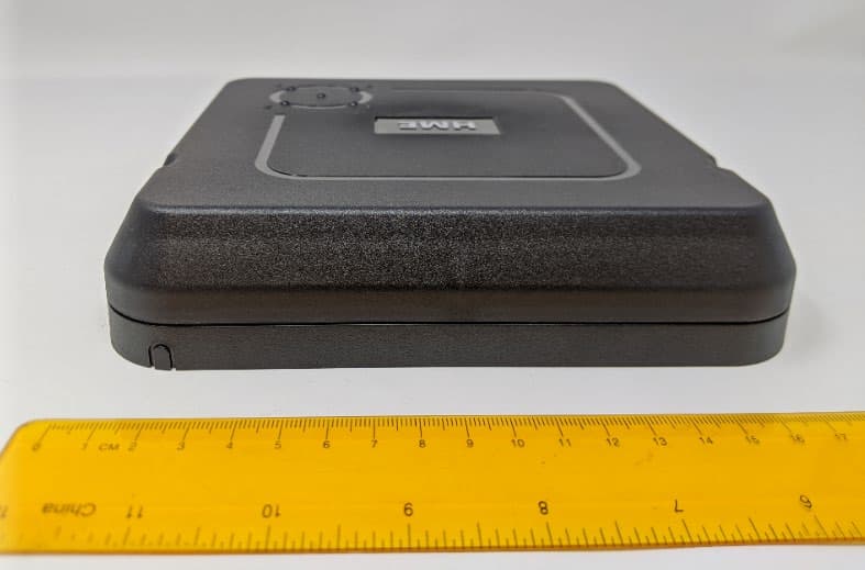
BYM7000
Mar 15, 2021Remote Transceiver
Equipment Class
NII - Unlicensed National Information Infrastructure TX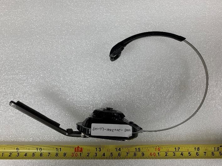
BYM7002
Mar 15, 2021Nexeo AIO headset
Equipment Class
DTS - Digital Transmission System
BYM-AC70
Dec 20, 2020Battery Charger
Equipment Class
DTS - Digital Transmission System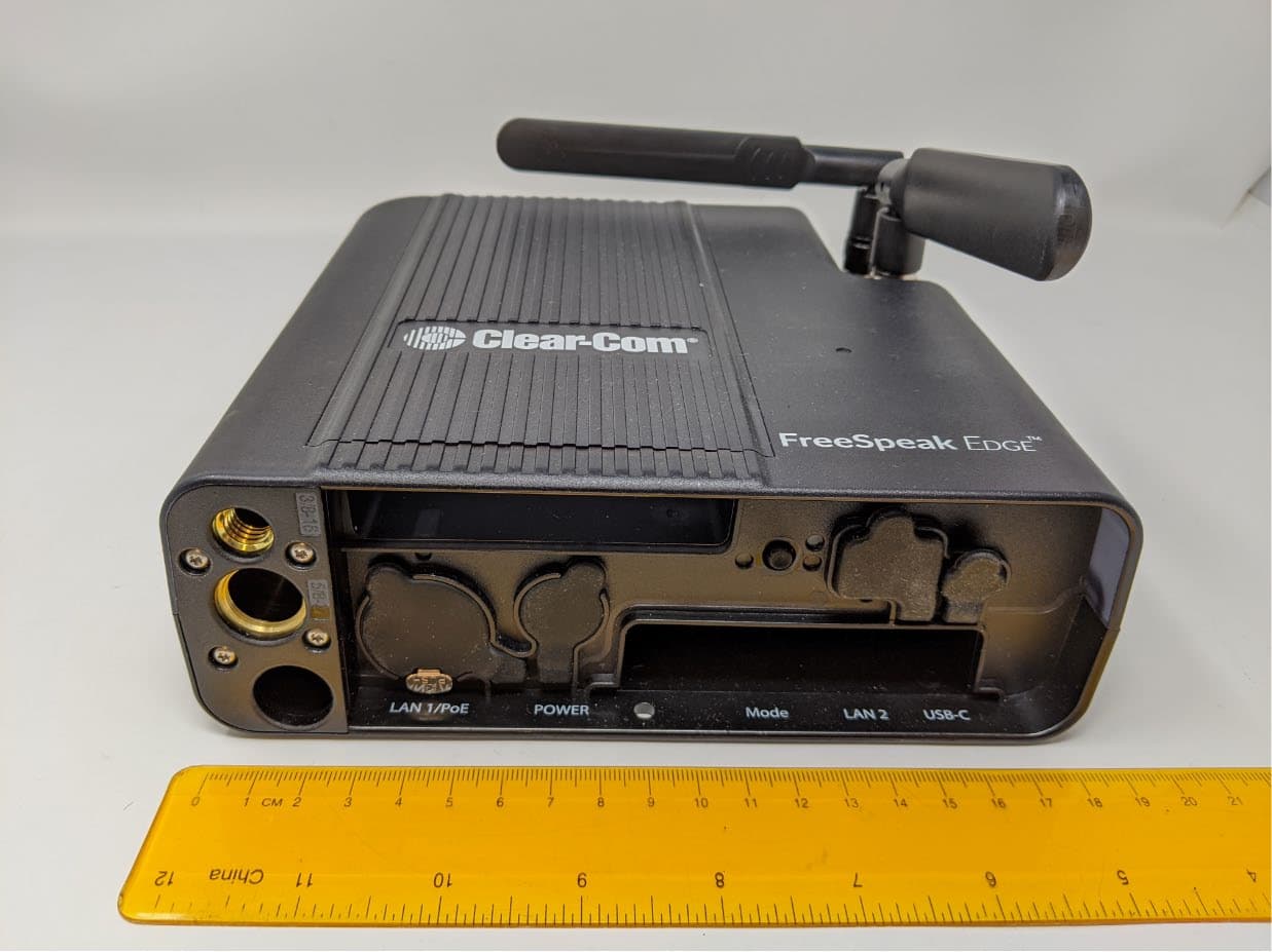
BYM1408
Jun 01, 2020Base Transceiver
Equipment Class
DTS - Digital Transmission System